EP0063717A2 - Transmission pour l'exécution de mouvements comportant des temps d'arrêt intercalaires - Google Patents
Transmission pour l'exécution de mouvements comportant des temps d'arrêt intercalaires Download PDFInfo
- Publication number
- EP0063717A2 EP0063717A2 EP82102866A EP82102866A EP0063717A2 EP 0063717 A2 EP0063717 A2 EP 0063717A2 EP 82102866 A EP82102866 A EP 82102866A EP 82102866 A EP82102866 A EP 82102866A EP 0063717 A2 EP0063717 A2 EP 0063717A2
- Authority
- EP
- European Patent Office
- Prior art keywords
- coupling
- curve
- rocker
- output
- transmission according
- Prior art date
- Legal status (The legal status is an assumption and is not a legal conclusion. Google has not performed a legal analysis and makes no representation as to the accuracy of the status listed.)
- Granted
Links
Images


Classifications
-
- F—MECHANICAL ENGINEERING; LIGHTING; HEATING; WEAPONS; BLASTING
- F16—ENGINEERING ELEMENTS AND UNITS; GENERAL MEASURES FOR PRODUCING AND MAINTAINING EFFECTIVE FUNCTIONING OF MACHINES OR INSTALLATIONS; THERMAL INSULATION IN GENERAL
- F16H—GEARING
- F16H21/00—Gearings comprising primarily only links or levers, with or without slides
- F16H21/10—Gearings comprising primarily only links or levers, with or without slides all movement being in, or parallel to, a single plane
- F16H21/40—Gearings comprising primarily only links or levers, with or without slides all movement being in, or parallel to, a single plane for interconverting rotary motion and oscillating motion
-
- F—MECHANICAL ENGINEERING; LIGHTING; HEATING; WEAPONS; BLASTING
- F02—COMBUSTION ENGINES; HOT-GAS OR COMBUSTION-PRODUCT ENGINE PLANTS
- F02B—INTERNAL-COMBUSTION PISTON ENGINES; COMBUSTION ENGINES IN GENERAL
- F02B2275/00—Other engines, components or details, not provided for in other groups of this subclass
- F02B2275/36—Modified dwell of piston in TDC
-
- Y—GENERAL TAGGING OF NEW TECHNOLOGICAL DEVELOPMENTS; GENERAL TAGGING OF CROSS-SECTIONAL TECHNOLOGIES SPANNING OVER SEVERAL SECTIONS OF THE IPC; TECHNICAL SUBJECTS COVERED BY FORMER USPC CROSS-REFERENCE ART COLLECTIONS [XRACs] AND DIGESTS
- Y10—TECHNICAL SUBJECTS COVERED BY FORMER USPC
- Y10T—TECHNICAL SUBJECTS COVERED BY FORMER US CLASSIFICATION
- Y10T74/00—Machine element or mechanism
- Y10T74/18—Mechanical movements
- Y10T74/18056—Rotary to or from reciprocating or oscillating
- Y10T74/18176—Crank, pitman, lever, and slide
Definitions
- the invention relates to a transmission for executing movements with downtimes switched on, consisting of an oscillatable quadrangle with the associated articulated members, the coupling curve being traversed only in part and being congruent in the outward and return travel, and a grid-generating output thrust.
- Such "latching gears” are used in many branches of technology, e.g. in the construction of high-quality processing machines, in machine tool construction and in precision engineering.
- cam gear units have been used almost exclusively to solve the corresponding tasks, with which any movement law can be implemented constructively, that is to say the often required high locking quality.
- the invention is therefore based on the object of creating a coupling detent gear with only a few articulated links, the coupling curve of which nevertheless enables the implementation of a precise and precisely limited detent.
- the coupling curve has a peak on its path, which divides it into two curves, a short curve is used to generate the grid, while a curve elongated at an angle brings about the movement derivation and the tip of the coupling curve with a momentary pole is identical, the beginning and end of the rest marked.
- the sharp separation of the coupling curve into two curves by a momentary pole as well as the very short curve serving to generate the raster enable on the one hand a precisely defined limitation of the rest and an extremely precise approximation to the target values due to the shortness of the raster generating curve.
- the universally usable basic gear for generating the coupling curve can be coupled with any drive without any problems and can also be derived, for example, from the main drive of the respective machine.
- this gear is also suitable for pronounced precision machines, which also include the printing machines, particularly because of the high locking quality that this enables.
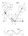
- the drive takes place by means of a sliding crank mechanism via a drive crank 1 and a coupling 2 articulated thereon, which is articulated on the drive rocker 4 mounted on the gestel point 3 of the articulated quadrilateral producing the coupling curve 5.
- Said quadrilateral is further composed of the drive arm 4 already mentioned; a double-armed coupling 7 connected to it at the articulation point 6 as well as a further rocker 10, which is articulated at the connection point 8 of its two arms 7.1, 7.2 and is mounted in the frame point 9.
- a grid-producing rocker arm 12 engages one, the articulated quadrilateral 3, 6,8,9 downstream output two-stop 12,13.
- the attached output rocker 13 brings the movement derivation with the interposed rest.
- the coupling curve 5 generated with the illustrated quadrilateral 3,6,8,9 can be separated into a short curve line 5.1, which is used for generating the grid, and a curve line 5.2, which is elongated at an angle 14 and produces the movement derivative.
- Both curves 5.1, 5.2 are sharply separated from one another by a tip 15, which runs through the coupling curve 5 on its path, said tip 15 of the coupling curve 5 being identical to a momentary pole 16, which thus also marks the beginning and end of the rest.
- the dimensions and positions of the quadrilateral joint 3,6,8,9 are to be determined with the aid of the polar curve method.
- the assembly to the present gear unit can be solved in a synthetic empirical procedure, as is known to every gear specialist.
- the detent that can be generated with this gear 1, 2, 4, 7, 10, 12, 13 is shown as the detent angle ⁇ R on the circular path 17 of the drive crank 1.
- the drive rocker 4 is provided with an adjustment slot 18, with the aid of which the point of application 19 of the driving coupling 2 can also be set continuously during operation.
- the radius of curvature 20 of the slot center line 21 is to be determined in the outer dead position of the transmission.
- the path-time diagram shown in FIG. 2 illustrates the relationship between crank angle ⁇ and output oscillation angle ⁇ and the adjustment range of the detent angle T R (dashed line).
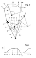
- Fig. 3 shows a further drive alternative for the raster-generating basic gear 4,7,10,12,13.
- a drive crank 1 drives the rocker 10 of the four-bar linkage 3, 6, 8, 9 via a link guide 22, which now acts as a drive rocker.
- the ratio of the movement variables ⁇ , ⁇ in a gearbox construction according to FIG. 3 can be seen from FIG. 4.
- This embodiment is therefore suitable for tasks that require such non-uniform operation.
- FIG. 5 shows an extended application of the coupling detent gear according to the invention.
- This combination coupling ratchet mechanism is used to generate two notches.
- the actual basic gears 4,7,10,12,13 are preceded by a further coupling ratchet mechanism of a conventional type.
- This receives its drive from a central coupling curve 25 of an existing thrust crank mechanism, consisting of the drive crank 1, the push rod 26 with link 27 and one, articulated on the output-side coupling point 28 of the push rod 26 and through the articulation point 29 with the drive rocker 4 of the basic transmission 4.7 , 10, 12, 13 connected connecting rod 30.
- the thrust crank mechanism could also be driven via the lifting movement of the link 27.
- it is a series connection of two detent gears for generating, in this case, two notches of the same size.
- This transmission also has the adjustment options already mentioned at the beginning.
- crank angle for this combination coupling ratchet mechanism and the output oscillating angle "is illustrated in FIG. 6, the locking angle ⁇ RI and ⁇ RII are shown as horizontal lines, it being noted that with the conventional latching mechanism (crank mechanism) ⁇ recoverable latching quality of the detent RI due to the only approximately circular arc shape of the raster-forming Curve 25.1 of the central coupling curve 25 remains behind the quality of the rest ⁇ RII .
- FIG. 7 shows a first application of the basic transmission.
- the output rocker 13 is coupled to the pivot lever 31 of the crucible 32 of a crucible printing machine 33. Its locking position corresponds to the abutment of the crucible 32 on the counterpressure plate 34, it being particularly important in the case of embossing crucibles that during the printing or. Embossing process, the pressing force of the crucible 32 remains as constant as possible.
- the basic gear 4, 7, 10, 12, 13 is driven, for example, via drive crank 1 and coupling 2.
- the frame points 35.9 of the output rocker 13 and the second rocker 10 of the four-bar linkage are collapsed for the sake of simplicity.
- the articulation point 3 fixed to the frame is the drive swing 4 with the tip 15 of the coupling curve 5, which is also the instantaneous pole 16, identical.
- the output rocker 13 of the raster-producing two-stroke mechanism 12, 13 is particularly advantageously suitable as a pivot lever 36 for ink or dampening levers 37 in offset or high-pressure machines.
- the combination coupling latching mechanism can be arranged in such a way that the latching with the higher quality corresponds with the system of the jack 37 on the ink fountain roller 38 or also with the system on the subsequent inking roller 29 in accordance with the requirements.
- the output lever 40 provided for this purpose is provided for this purpose with a guide slot 41 corresponding to the grid-producing short curve 5.1, in which the end point 11 of the output-side coupling arm 7.2 of the oscillating articulated quadrilateral designed as a sliding block 42 moves. If one designs the said quadrilateral joint as a drilling or milling device, then the exact guide slot 41 in the output lever 40 can be produced. The absolute locking accuracy is guaranteed.
- the invention is of course in no way limited to the illustrated embodiments and uses.
- the serving the generation of the coupler curve universal basic transmission allows namely an upstream multi-membered linkage diverse gear combinations, so that can be done from the Antriebshertechnisch for the basic transmission from a point 'a coupling, thrust or circular motion.
- the derivation of motion can take place from any point on a thrust plane.
- this gear it is possible in a simple manner to convert the detent resulting from a pivoting movement of the output rocker as the standstill of a lifting movement of a ram guided in the longitudinal direction.
Landscapes
- Engineering & Computer Science (AREA)
- General Engineering & Computer Science (AREA)
- Mechanical Engineering (AREA)
- Transmission Devices (AREA)
- Inking, Control Or Cleaning Of Printing Machines (AREA)
- Rotary Presses (AREA)
Applications Claiming Priority (2)
| Application Number | Priority Date | Filing Date | Title |
|---|---|---|---|
| DE3116172A DE3116172C2 (de) | 1981-04-23 | 1981-04-23 | "Getriebe zur Ausführung von Bewegungen mit eingeschalteten Stillstandszeiten" |
| DE3116172 | 1981-04-23 |
Publications (3)
| Publication Number | Publication Date |
|---|---|
| EP0063717A2 true EP0063717A2 (fr) | 1982-11-03 |
| EP0063717A3 EP0063717A3 (en) | 1983-11-16 |
| EP0063717B1 EP0063717B1 (fr) | 1986-05-28 |
Family
ID=6130687
Family Applications (1)
| Application Number | Title | Priority Date | Filing Date |
|---|---|---|---|
| EP82102866A Expired EP0063717B1 (fr) | 1981-04-23 | 1982-04-03 | Transmission pour l'exécution de mouvements comportant des temps d'arrêt intercalaires |
Country Status (4)
| Country | Link |
|---|---|
| US (1) | US4416198A (fr) |
| EP (1) | EP0063717B1 (fr) |
| JP (3) | JPS57205438U (fr) |
| DE (2) | DE3116172C2 (fr) |
Families Citing this family (8)
| Publication number | Priority date | Publication date | Assignee | Title |
|---|---|---|---|---|
| AU664692B2 (en) * | 1990-11-09 | 1995-11-30 | Greencare Pty Limited | Drive linkage for agricultural device |
| US5320208A (en) * | 1992-07-02 | 1994-06-14 | Utica Enterprises, Inc. | Reciprocating lift mechanism |
| DE19835005B4 (de) * | 1997-12-20 | 2016-08-11 | Heidelberger Druckmaschinen Ag | Kurvengesteuertes Leistungsausgleichsgetriebe für ein Bogenbeschleunigungssystem |
| US6935228B2 (en) * | 2000-05-17 | 2005-08-30 | Brandtjen & Kluge, Inc. | Platen press |
| WO2002059468A1 (fr) * | 2001-01-26 | 2002-08-01 | Helmut Obieglo | Moteur a combustion interne a bielle articulee et temps allonge au point mort haut |
| US9782817B2 (en) | 2014-06-10 | 2017-10-10 | Getter Dunn Technologies, Llc | System and method of varying dwell time in a honeycomb plate press |
| WO2016057501A1 (fr) * | 2014-10-09 | 2016-04-14 | Phoenix Partners, Llc | Presse de type coquille réglable |
| US10915672B2 (en) * | 2017-08-31 | 2021-02-09 | Autodesk, Inc. | Computer-implemented synthesis of a four-bar linkage |
Family Cites Families (15)
| Publication number | Priority date | Publication date | Assignee | Title |
|---|---|---|---|---|
| DE670678C (de) * | 1939-01-23 | Leo Hagedorn | Koppelgetriebe | |
| US346635A (en) * | 1886-08-03 | Dewend | ||
| DE428026C (de) * | 1926-04-23 | George Constantinesco | Verfahren und Einrichtungen zur Leistungsuebertragung | |
| US667772A (en) * | 1900-08-15 | 1901-02-12 | Barnhart Brothers & Spindler | Throw-off attachment for printing-presses. |
| US1095675A (en) * | 1911-06-01 | 1914-05-05 | Giacomo Rietti | Combustion-engine. |
| US1121705A (en) * | 1912-10-22 | 1914-12-22 | Harris Automatic Press Co | Actuating means for fountain-rolls for printing-presses. |
| US1656601A (en) * | 1922-06-14 | 1928-01-17 | Smithe Machine Co Inc F L | Plunger mechanism |
| DE566021C (de) * | 1929-09-18 | 1932-12-08 | Hermann Alt Dr | Getriebe zur Ausfuehrung von Bewegungen mit eingeschalteten Stillstandszeiten |
| DE719040C (de) * | 1936-09-04 | 1943-01-12 | Wuerker Fa | Getriebe fuer Steuerbewegungen, insbesondere fuer die Erzeugung von Stillstaenden |
| US2574137A (en) * | 1946-03-22 | 1951-11-06 | Teletype Corp | Stop for reciprocating members |
| US2503037A (en) * | 1948-08-23 | 1950-04-04 | Danly Mach Specialties Inc | Multiple action power press |
| US2523430A (en) * | 1948-08-23 | 1950-09-26 | Henry T Hearn | Reciprocating die actuating means |
| FR59274E (fr) * | 1949-05-09 | 1954-05-24 | Transmission à levier entre le piston et l'arbre coudé pour moteurs et autres machines | |
| DE1217539B (de) * | 1957-10-29 | 1966-05-26 | Liebrandt Karl | Kettenwirkmaschine |
| CH422013A (de) * | 1964-02-19 | 1966-10-15 | Roland Offsetmaschf | Farbwerk |
-
1981
- 1981-04-23 DE DE3116172A patent/DE3116172C2/de not_active Expired
-
1982
- 1982-04-03 DE DE8282102866T patent/DE3271329D1/de not_active Expired
- 1982-04-03 EP EP82102866A patent/EP0063717B1/fr not_active Expired
- 1982-04-22 US US06/370,622 patent/US4416198A/en not_active Expired - Fee Related
- 1982-04-23 JP JP1982058582U patent/JPS57205438U/ja active Pending
- 1982-04-23 JP JP57067517A patent/JPS57184746A/ja active Pending
-
1988
- 1988-11-17 JP JP1988149106U patent/JPH01139162U/ja active Pending
Also Published As
| Publication number | Publication date |
|---|---|
| DE3271329D1 (en) | 1986-07-03 |
| DE3116172C2 (de) | 1983-03-03 |
| EP0063717B1 (fr) | 1986-05-28 |
| DE3116172A1 (de) | 1982-11-11 |
| JPH01139162U (fr) | 1989-09-22 |
| EP0063717A3 (en) | 1983-11-16 |
| JPS57205438U (fr) | 1982-12-27 |
| US4416198A (en) | 1983-11-22 |
| JPS57184746A (en) | 1982-11-13 |
Similar Documents
| Publication | Publication Date | Title |
|---|---|---|
| DE3322944C2 (de) | Matrizenauswerfer-Vorrichtung für Mehrstufen-Umformmaschinen | |
| DE2755361C2 (de) | Falzklappenzylinder für Rotationsfalzwerk | |
| EP0241798A2 (fr) | Pince pour sertissage des bornes de câbles, des connecteurs de câbles, et semblables avec des connecteurs électriques, des guides d'ondes etc... | |
| DE2439722B2 (de) | Bewegungsgetriebe fuer ein arbeitsorgan | |
| EP0022122A1 (fr) | Machine de cintrage | |
| EP0242661A2 (fr) | Dispositif de positionnement d'un ensemble d'impression à cinq cylindres d'une rotative offset | |
| EP0392205B1 (fr) | Machine rotative d'impression pour feuilles avec plusieurs unités pour impression en blanc et impression en blanc en retiration | |
| EP0063717B1 (fr) | Transmission pour l'exécution de mouvements comportant des temps d'arrêt intercalaires | |
| EP1336440A1 (fr) | Dispositif pour le mouvement des pièces avec des barres d'amenage | |
| DE3623647A1 (de) | Vorrichtung zum schrittweisen vorschieben von bandmaterial mit zwei gegenlaeufig angetriebenen vorschubwalzen | |
| DE2340263A1 (de) | Antrieb fuer mehrfarben-bogenrotationsmaschinen in reihenanordnung mit mindestens zwei druckwerken | |
| WO2001051234A1 (fr) | Dispositif monte sur une manivelle a coulisse, destine a produire un mouvement d'une partie montee sur le coulisseau par rapport a ce dernier | |
| DE2507098C3 (de) | Metallbearbeitungspresse, insbesondere Ziehpresse | |
| DE4442302B4 (de) | Vorrichtung zum axialen hin- und herbewegen von Reibwalzen im Farbwerk von Druckmaschinen | |
| EP0041690B1 (fr) | Machine-outil à plusieurs étages travaillant le métal par formage | |
| DE3001630C2 (de) | Antriebsvorrichtung | |
| DE2402836C2 (de) | Siebdruckvorrichtung mit wenigstens zwei Druckstationen | |
| EP0480879A1 (fr) | Dispositif de réglage continu du mouvement de distribution axial de rouleaux distributeurs | |
| DE3809802A1 (de) | Einrichtung zur steuerung der werkzeugstellung in abhaengigkeit von der hubposition | |
| DE10143042A1 (de) | Vorrichtung zum Falzen von Druckexemplaren | |
| DE3222128A1 (de) | Intermittierend arbeitende vorschubeinrichtung, insbesondere zangenvorschubeinrichtung fuer exzenterpressen | |
| DE2911576A1 (de) | Schnellaufende maschine zum kaltschmieden von schrauben, nieten u.ae. hartwaren | |
| EP0515882B1 (fr) | Appareil pour le changement du rapport de levier d'un levier oscillant à deux bras | |
| DE2126697A1 (de) | Vorrichtung mit Spindelantrieb zum Anheben von Papierrollen und dergleichen schweren zylindrischen Gegenständen | |
| DE1140207B (de) | Schaltantrieb fuer die Farbkastenwalze einer Druckmaschine |
Legal Events
| Date | Code | Title | Description |
|---|---|---|---|
| PUAI | Public reference made under article 153(3) epc to a published international application that has entered the european phase |
Free format text: ORIGINAL CODE: 0009012 |
|
| AK | Designated contracting states |
Designated state(s): CH DE FR GB IT |
|
| PUAL | Search report despatched |
Free format text: ORIGINAL CODE: 0009013 |
|
| AK | Designated contracting states |
Designated state(s): CH DE FR GB IT LI |
|
| 17P | Request for examination filed |
Effective date: 19831209 |
|
| GRAA | (expected) grant |
Free format text: ORIGINAL CODE: 0009210 |
|
| AK | Designated contracting states |
Kind code of ref document: B1 Designated state(s): CH DE FR GB IT LI |
|
| REF | Corresponds to: |
Ref document number: 3271329 Country of ref document: DE Date of ref document: 19860703 |
|
| ITF | It: translation for a ep patent filed | ||
| ET | Fr: translation filed | ||
| PLBE | No opposition filed within time limit |
Free format text: ORIGINAL CODE: 0009261 |
|
| STAA | Information on the status of an ep patent application or granted ep patent |
Free format text: STATUS: NO OPPOSITION FILED WITHIN TIME LIMIT |
|
| 26N | No opposition filed | ||
| PG25 | Lapsed in a contracting state [announced via postgrant information from national office to epo] |
Ref country code: GB Effective date: 19890403 |
|
| PG25 | Lapsed in a contracting state [announced via postgrant information from national office to epo] |
Ref country code: LI Effective date: 19890430 Ref country code: CH Effective date: 19890430 |
|
| GBPC | Gb: european patent ceased through non-payment of renewal fee | ||
| PG25 | Lapsed in a contracting state [announced via postgrant information from national office to epo] |
Ref country code: FR Free format text: LAPSE BECAUSE OF NON-PAYMENT OF DUE FEES Effective date: 19891228 |
|
| REG | Reference to a national code |
Ref country code: CH Ref legal event code: PL |
|
| REG | Reference to a national code |
Ref country code: FR Ref legal event code: ST |
|
| PGFP | Annual fee paid to national office [announced via postgrant information from national office to epo] |
Ref country code: DE Payment date: 19940505 Year of fee payment: 13 |
|
| EUG | Se: european patent has lapsed |
Ref document number: 82102866.9 Effective date: 19821216 |
|
| PG25 | Lapsed in a contracting state [announced via postgrant information from national office to epo] |
Ref country code: DE Effective date: 19960103 |