EP0063729A2 - Dispositif pour l'inversion et le mélange de matières en écoulement - Google Patents
Dispositif pour l'inversion et le mélange de matières en écoulement Download PDFInfo
- Publication number
- EP0063729A2 EP0063729A2 EP82103009A EP82103009A EP0063729A2 EP 0063729 A2 EP0063729 A2 EP 0063729A2 EP 82103009 A EP82103009 A EP 82103009A EP 82103009 A EP82103009 A EP 82103009A EP 0063729 A2 EP0063729 A2 EP 0063729A2
- Authority
- EP
- European Patent Office
- Prior art keywords
- guide surfaces
- tube
- flow
- axis
- pipe
- Prior art date
- Legal status (The legal status is an assumption and is not a legal conclusion. Google has not performed a legal analysis and makes no representation as to the accuracy of the status listed.)
- Granted
Links
Images


Classifications
-
- B—PERFORMING OPERATIONS; TRANSPORTING
- B01—PHYSICAL OR CHEMICAL PROCESSES OR APPARATUS IN GENERAL
- B01J—CHEMICAL OR PHYSICAL PROCESSES, e.g. CATALYSIS OR COLLOID CHEMISTRY; THEIR RELEVANT APPARATUS
- B01J19/00—Chemical, physical or physico-chemical processes in general; Their relevant apparatus
- B01J19/30—Loose or shaped packing elements, e.g. Raschig rings or Berl saddles, for pouring into the apparatus for mass or heat transfer
- B01J19/305—Supporting elements therefor, e.g. grids, perforated plates
-
- B—PERFORMING OPERATIONS; TRANSPORTING
- B01—PHYSICAL OR CHEMICAL PROCESSES OR APPARATUS IN GENERAL
- B01F—MIXING, e.g. DISSOLVING, EMULSIFYING OR DISPERSING
- B01F25/00—Flow mixers; Mixers for falling materials, e.g. solid particles
- B01F25/40—Static mixers
- B01F25/42—Static mixers in which the mixing is affected by moving the components jointly in changing directions, e.g. in tubes provided with baffles or obstructions
- B01F25/43—Mixing tubes, e.g. wherein the material is moved in a radial or partly reversed direction
- B01F25/431—Straight mixing tubes with baffles or obstructions that do not cause substantial pressure drop; Baffles therefor
- B01F25/4315—Straight mixing tubes with baffles or obstructions that do not cause substantial pressure drop; Baffles therefor the baffles being deformed flat pieces of material
- B01F25/43151—Straight mixing tubes with baffles or obstructions that do not cause substantial pressure drop; Baffles therefor the baffles being deformed flat pieces of material composed of consecutive sections of deformed flat pieces of material
Definitions
- the present invention relates to a device for inverting and mixing flowing substances in a tube of any cross-section with at least one mixing element, consisting of guide surfaces, through which fluid elements flowing in the tube center are transported to the outside and fluid elements flowing outside to the inside ("flow inverter").
- flow inverter a device for inverting and mixing flowing substances in a tube of any cross-section with at least one mixing element, consisting of guide surfaces, through which fluid elements flowing in the tube center are transported to the outside and fluid elements flowing outside to the inside
- flow inverter a device for inverting and mixing flowing substances in a tube of any cross-section with at least one mixing element, consisting of guide surfaces, through which fluid elements flowing in the tube center are transported to the outside and fluid elements flowing outside to the inside
- Fluid should be understood to mean liquids, gases or free-flowing solids, as well as single or multi-phase mixtures of liquid, gaseous and / or solid components.
- a mixing device which consists of a number of oppositely inclined flow channels, which are open towards each other and act in relation to the flow division similarly to the above-mentioned arrangements.
- each mixing element consisting of an even number of sector-shaped guide surfaces and optionally of boundary surfaces.
- the task of the guide surfaces is the fluid transport in the radial direction from outside to inside and from inside to outside.
- the guide surfaces represent sections of the outer surface of cones and pyramids with a tip in the tube axis, the generatrix of the cone surface with the tube axis forming a constant or radial and circumferential angle of attack from 10 ° to 70 °.
- a mixing element can, for example, only be constructed from guide surfaces without boundary surfaces, the guide surfaces either pointing inwards or outwards and the backflow not being directed, or alternating guide surfaces pointing inwards and outwards alternate in the circumferential direction.
- Boundary surfaces are either flat surfaces, which preferably extend in the axial and radial direction with their main axes, or helices around the pipe axis.
- a complete, mixture-free shifting of the entire inner region of a pipe flow ("inner flow”) to the outside and the outer area (“outer flow”) to the inside is achieved according to the invention by a device in which an inlet duct first separates the inner region of the pipe flow from the outer region, then an inlet distributor Internal flow as well as the external flow each summarizes and distributed over an even number of flow channels, each flow channel filling a sector of the free pipe cross section.
- the subsequent division of the internal flow from its channels to the outside, and the outside flow to the inside, can be effected most simply by means of a distributor which is identical to the inlet distributor and is arranged in a mirror image of this, as well as offset by a sector.
- the distributor can be constructed by a suitable arrangement of guide surfaces and boundary surfaces of the type described above.
- the device By means of the device according to the invention, a shifting of a pipe flow from the inside to the outside and from the outside to the inside is brought about in a simple manner, so that the heat transfer in wall-heated or cooled pipes is thereby substantially improved.
- the device is suitable for all traditional areas of application of static mixers. t ..
- Another advantageous area of application is pipes that are filled with a solid bed (adsorbent, catalyst, etc.) and have a large pressure loss when flowing through them.
- the device according to the invention as a filler, provides for loosening and thus for a more uniform flow as well as for a reduction in pressure loss as a result of the improvement of the wall heat transfer, without the formation of flow passages ("edge movement").
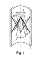
- Figure 1 shows a basic form of the device according to the invention in the cut tube in a perspective view.
- An even number of guide surfaces 2 are attached in a tube 1.
- the guide surfaces 2 consist of cutouts from the outer surface of two identical straight cones, the common axis of which Axis of tube 1 coincides.
- the generatrix of the conical surface with the tube axis form an angle of attack of preferably 25 ° to 45 °.
- the individual guide surfaces 2 are alternately inclined inwards and outwards in the manner shown and lie on the inner wall of the tube 1 with outer cut edges 3.
- the arrangement shown is symmetrical with respect to the direction of flow.
- Three baffles 9 each separate the flow from the wall and guide it inwards, three other baffles 8 guide the flow from the inside to the wall.
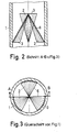
- Figures 2 and 3 show the device shown in Figure 1 in longitudinal and cross section.
- FIG. 4 A further advantageous embodiment of the device according to the invention is shown in FIG. 4.
- the guide surfaces 2 which follow one another in the circumferential direction are each shifted by a constant amount in the axial direction with the same direction of inclination.
- the outer cutting edge 3 of the guide surfaces 2 has an angle of incidence different from 90 ° with the direction of the tube axis.
- the angle of attack in the range from 45 ° to 800, the radial (outward or inward) flow direction of the guide surfaces 2 is superimposed on a component in the circumferential direction.
- the guide surfaces 2 with inner cut edges 4 can rest against a central tube 14 or be firmly connected to it, the heat transfer being improved not only to the tube 1 but also to the central tube 14 by the device according to the invention.
- FIG. 5 A further advantageous embodiment of the invention is shown in FIG. 5 in a cut-open tube in perspective, FIG. 6 in longitudinal section and FIG. 7 in cross section.
- the individual, alternating inward and outward guide surfaces 2 are separated from each other by boundary surfaces 5 over a certain area of the radius, the boundary surfaces 5 abutting lateral cutting edges 6 of the guide surfaces 2, so that flow channels are formed in which the fluid alternately follows is transported inside and outside. This avoids a flow around the web of the guide surfaces 2 in the region of the boundary surfaces 5 and improves the circulation from the inside to the outside.
- the flow diagram is outlined in FIG.
- the boundary surfaces 5 can either lie in one of their main axes parallel to the pipe axis (FIG. 5-7) or wind in the form of spirals around the pipe axis.
- the guide surfaces 2 are preferably formed from the lateral surface of straight cones or pyramids, but single or multiple curved shapes can also be used, as outlined in longitudinal section in FIG. It can also be advantageous to provide cutouts or cutouts in the guide surfaces. This applies in particular to the design of the outer cutting edge 3 and its connection to the pipe wall.
- Figure 9 shows some design options. A gap 7 on the front face of the guide surface and a stagnation area on the back of the guide surface can be avoided by a defined gap 7. In the direction of flow, successive guide surfaces 2 can either overlap with their lateral cutting edges 6 or leave a space,
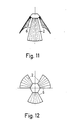
- FIGS. 11 and 12 show as an example a single element with three guide surfaces 2 in a perspective view and in a top view
- FIG. 13 shows the diagram of the nesting of these elements in longitudinal section.
- the device consists of guide surfaces 2 which guide the flow either only inwards or only outwards.
- the backflow is non-directional.
- FIG. 14 shows a corresponding example of three successive guide surface groups in the cut tube in a perspective view.
- successive guide surface groups are rotated so that blocked and unblocked pipe cross-section sectors alternate with one another.
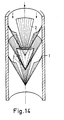
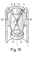
- a device according to the invention for shifting the entire outer region of a pipe flow inwards and the entire inner region outwards is outlined in perspective in FIG. 15, in longitudinal section in FIG. 16 and in plan view in FIG.
- the device shown consists of two mirror-inverted parts which are connected to one another by 90 °.
- the part at the front in the direction of flow (inflow from above) is referred to below as an inlet distributor. It consists of the four boundary surfaces 5, which extend with their main axes in the axial and radial directions, as well as two outwardly directed guide surfaces 8 and two inwardly directed guide surfaces 9, which are composed such that the inner cutting edges 4 of the outside facing guide surfaces 8 with the outer cutting edges 3 of the internally facing guide surfaces 9 form an inlet channel which separates the outside and inside flow.
- the task of the outwardly directed guide surfaces 8 is to combine the external flow into two flow channels 10 which lie opposite one another and which, in the form of two 90 ° sectors, fill half of the pipe cross section.
- the two inward-facing guide surfaces distribute the internal flow over two flow channels 11.
- the outward-facing guide surfaces 8 lie with their outer cutting edge 13 on the pipe 1
- the inward-facing guide surfaces 9 either meet with their tips (FIGS. 15-17) , or abut with their inner cutting edges on a central tube, not shown.
- the greatest radial extent of the boundary surfaces 5 extends from the pipe axis or the central pipe to the inner wall of the pipe 1.
- the distribution of the internal flow from the flow channels 11 to the outside area and the outside flow from the flow channels 10 to the inside area is carried out by a device, which corresponds to the inlet distributor and is turned upside down and rotated by a sector adjoining this.
- the outwardly facing guide surfaces 8 have a continuously variable over the periphery angle of 45 ° to 74 0th This also prevents the flow from jamming on the underside of the guide surface.
- the inlet channel or the outlet channel which is a mirror image, can be extended by a Ror committee 12, which prevents rapid mixing of the outside and inside flow.
Landscapes
- Chemical & Material Sciences (AREA)
- Chemical Kinetics & Catalysis (AREA)
- Physics & Mathematics (AREA)
- Thermal Sciences (AREA)
- Organic Chemistry (AREA)
- Dispersion Chemistry (AREA)
- Paper (AREA)
- Processing And Handling Of Plastics And Other Materials For Molding In General (AREA)
- Sewage (AREA)
Priority Applications (1)
| Application Number | Priority Date | Filing Date | Title |
|---|---|---|---|
| AT82103009T ATE25201T1 (de) | 1981-04-25 | 1982-04-08 | Vorrichtung zur invertierung und mischung von stroemenden stoffen. |
Applications Claiming Priority (2)
| Application Number | Priority Date | Filing Date | Title |
|---|---|---|---|
| DE19813116557 DE3116557A1 (de) | 1981-04-25 | 1981-04-25 | Vorrichtung zur invertierung und mischung von stroemenden stoffen |
| DE3116557 | 1981-04-25 |
Publications (3)
| Publication Number | Publication Date |
|---|---|
| EP0063729A2 true EP0063729A2 (fr) | 1982-11-03 |
| EP0063729A3 EP0063729A3 (en) | 1984-08-01 |
| EP0063729B1 EP0063729B1 (fr) | 1987-01-28 |
Family
ID=6130860
Family Applications (1)
| Application Number | Title | Priority Date | Filing Date |
|---|---|---|---|
| EP82103009A Expired EP0063729B1 (fr) | 1981-04-25 | 1982-04-08 | Dispositif pour l'inversion et le mélange de matières en écoulement |
Country Status (3)
| Country | Link |
|---|---|
| EP (1) | EP0063729B1 (fr) |
| AT (1) | ATE25201T1 (fr) |
| DE (2) | DE3116557A1 (fr) |
Cited By (19)
| Publication number | Priority date | Publication date | Assignee | Title |
|---|---|---|---|---|
| WO1986006296A1 (fr) * | 1985-04-27 | 1986-11-06 | Gerd Wilhelm | Materiau de garnissage tourbillonnaire forme d'elements de type pyramidal et procede de construction de l'emballage |
| EP0226879A1 (fr) * | 1985-12-11 | 1987-07-01 | GebràDer Sulzer Aktiengesellschaft | Mélangeur statique pour fluides comportant des composés de particules solides |
| WO1989000076A1 (fr) * | 1987-06-29 | 1989-01-12 | Moore Barrett And Redwood Limited | Melangeur statique pour fluides |
| EP0430973A4 (en) * | 1988-07-27 | 1991-12-11 | Vortab Corporation | Static fluid flow mixing apparatus |
| US5456533A (en) * | 1991-07-30 | 1995-10-10 | Sulzer Brothers Limited | Static mixing element having deflectors and a mixing device |
| WO1996023981A1 (fr) * | 1995-02-03 | 1996-08-08 | Bmw Rolls-Royce Gmbh | Corps de guidage de l'ecoulement pour chambres de combustion de turbines a gaz |
| WO1996035508A1 (fr) * | 1995-05-09 | 1996-11-14 | Labatt Brewing Company Limited | Reacteur photochimique a circulation |
| US5800059A (en) * | 1995-05-09 | 1998-09-01 | Labatt Brewing Company Limited | Static fluid flow mixing apparatus |
| EP0956897A3 (fr) * | 1998-05-11 | 2000-12-06 | BBP Environment GmbH | Dispositif pour mélanger un gaz passant un conduit |
| EP1153650A1 (fr) * | 2000-05-08 | 2001-11-14 | Sulzer Chemtech AG | Elément de mélange pour une jonction à flasques dans un tuyau |
| US6394644B1 (en) * | 1999-06-21 | 2002-05-28 | Koch-Glitsch, Inc. | Stacked static mixing elements |
| US6615872B2 (en) * | 2001-07-03 | 2003-09-09 | General Motors Corporation | Flow translocator |
| US6773156B2 (en) * | 2002-07-10 | 2004-08-10 | Tah Industries, Inc. | Method and apparatus for reducing fluid streaking in a motionless mixer |
| US6986832B2 (en) | 2001-02-21 | 2006-01-17 | Metso Paper Inc. | Arrangement for mixing flows in papermaking process |
| US7040802B2 (en) * | 2002-12-13 | 2006-05-09 | Sulzer Chemtech Ag | Static mixer for high-viscosity media employing arcuate segments for mounting in a sleeve |
| EP1754530A1 (fr) | 2005-08-18 | 2007-02-21 | StaMixCo Technology AG | Elément mélangeur pour l'inversion et le mélange de matières en écoulement dans un canal d'écoulement, ensemble et mélangeur comprenant de tels éléments mélangeurs, et procédé pour mélanger une matière en écoulement dans un canal d'écoulement |
| US7383850B2 (en) | 2005-01-18 | 2008-06-10 | Peerless Mfg. Co. | Reagent injection grid |
| FR2957118A1 (fr) * | 2010-03-02 | 2011-09-09 | Peugeot Citroen Automobiles Sa | Chambre de melange d'un produit reducteur a des gaz d'echappement |
| CN116367917A (zh) * | 2020-09-02 | 2023-06-30 | 南非大学 | 管状反应器 |
Families Citing this family (5)
| Publication number | Priority date | Publication date | Assignee | Title |
|---|---|---|---|---|
| DE19544816A1 (de) * | 1995-12-01 | 1997-06-05 | Abb Research Ltd | Mischvorrichtung |
| DE19730227A1 (de) * | 1997-07-15 | 1999-01-21 | Abb Patent Gmbh | Verfahren zur Verbrennung von unbehandeltem Müll in einer Müllverbrennungsanlage |
| DE19748383C2 (de) * | 1997-11-03 | 2000-11-23 | U & A Gmbh | Statischer Mischer |
| CN1204945C (zh) * | 2003-09-05 | 2005-06-08 | 刘兆彦 | 一种管、筒或塔内构件立交盘 |
| ES2451566T3 (es) | 2011-12-19 | 2014-03-27 | Sick Engineering Gmbh | Enderezador de flujo |
Family Cites Families (6)
| Publication number | Priority date | Publication date | Assignee | Title |
|---|---|---|---|---|
| DE315382C (fr) * | ||||
| GB741030A (en) * | 1953-11-03 | 1955-11-23 | Atomic Energy Authority Uk | Improvements in or relating to random packed elements for distillation and chemical process columns |
| GB891212A (en) * | 1959-08-21 | 1962-03-14 | Du Pont | Liquid flow controlling means |
| DE2128874A1 (de) * | 1971-06-11 | 1973-01-04 | Gerhard Prof Dr Ing Schenkel | Radialausgleicher fuer laminare druckstroemungen, insbesondere laminare rohrstroemungen |
| US3923288A (en) * | 1973-12-27 | 1975-12-02 | Komax Systems Inc | Material mixing apparatus |
| PL101135B1 (pl) * | 1976-03-31 | 1978-12-30 | Osrodek Badawczorozwojowy Przemyslu Budowy Urzadzen Chemiczynch "Cebea" Te Krakow Polen | Element wypelniajacy |
-
1981
- 1981-04-25 DE DE19813116557 patent/DE3116557A1/de not_active Withdrawn
-
1982
- 1982-04-08 AT AT82103009T patent/ATE25201T1/de not_active IP Right Cessation
- 1982-04-08 EP EP82103009A patent/EP0063729B1/fr not_active Expired
- 1982-04-08 DE DE8282103009T patent/DE3275270D1/de not_active Expired
Cited By (28)
| Publication number | Priority date | Publication date | Assignee | Title |
|---|---|---|---|---|
| US4830792A (en) * | 1985-04-27 | 1989-05-16 | Gerd Wilhelm | Vortex-inducing packing of pyramid-type elements and process for its assembly |
| WO1986006296A1 (fr) * | 1985-04-27 | 1986-11-06 | Gerd Wilhelm | Materiau de garnissage tourbillonnaire forme d'elements de type pyramidal et procede de construction de l'emballage |
| EP0226879A1 (fr) * | 1985-12-11 | 1987-07-01 | GebràDer Sulzer Aktiengesellschaft | Mélangeur statique pour fluides comportant des composés de particules solides |
| WO1989000076A1 (fr) * | 1987-06-29 | 1989-01-12 | Moore Barrett And Redwood Limited | Melangeur statique pour fluides |
| EP0430973A4 (en) * | 1988-07-27 | 1991-12-11 | Vortab Corporation | Static fluid flow mixing apparatus |
| USRE36969E (en) * | 1991-07-30 | 2000-11-28 | Sulzer Brothers Limited | Static mixing element having deflectors and a mixing device |
| US5456533A (en) * | 1991-07-30 | 1995-10-10 | Sulzer Brothers Limited | Static mixing element having deflectors and a mixing device |
| WO1996023981A1 (fr) * | 1995-02-03 | 1996-08-08 | Bmw Rolls-Royce Gmbh | Corps de guidage de l'ecoulement pour chambres de combustion de turbines a gaz |
| US5918465A (en) * | 1995-02-03 | 1999-07-06 | Bmw Rolls-Royce Gmbh | Flow guiding body for a gas turbine combustion chamber |
| US5696380A (en) * | 1995-05-09 | 1997-12-09 | Labatt Brewing Company Limited | Flow-through photo-chemical reactor |
| US5800059A (en) * | 1995-05-09 | 1998-09-01 | Labatt Brewing Company Limited | Static fluid flow mixing apparatus |
| US5866910A (en) * | 1995-05-09 | 1999-02-02 | Labatt Brewing Company Limited | Flow-through photo-chemical reactor |
| US5994705A (en) * | 1995-05-09 | 1999-11-30 | Labatt Brewing Company Limited | Flow-through photo-chemical reactor |
| WO1996035508A1 (fr) * | 1995-05-09 | 1996-11-14 | Labatt Brewing Company Limited | Reacteur photochimique a circulation |
| EP0956897A3 (fr) * | 1998-05-11 | 2000-12-06 | BBP Environment GmbH | Dispositif pour mélanger un gaz passant un conduit |
| US6394644B1 (en) * | 1999-06-21 | 2002-05-28 | Koch-Glitsch, Inc. | Stacked static mixing elements |
| EP1153650A1 (fr) * | 2000-05-08 | 2001-11-14 | Sulzer Chemtech AG | Elément de mélange pour une jonction à flasques dans un tuyau |
| US6595682B2 (en) | 2000-05-08 | 2003-07-22 | Sulzer Chemtech Ag | Mixing element for a flange transition in a pipeline |
| US6986832B2 (en) | 2001-02-21 | 2006-01-17 | Metso Paper Inc. | Arrangement for mixing flows in papermaking process |
| US6615872B2 (en) * | 2001-07-03 | 2003-09-09 | General Motors Corporation | Flow translocator |
| US6773156B2 (en) * | 2002-07-10 | 2004-08-10 | Tah Industries, Inc. | Method and apparatus for reducing fluid streaking in a motionless mixer |
| US7040802B2 (en) * | 2002-12-13 | 2006-05-09 | Sulzer Chemtech Ag | Static mixer for high-viscosity media employing arcuate segments for mounting in a sleeve |
| US7383850B2 (en) | 2005-01-18 | 2008-06-10 | Peerless Mfg. Co. | Reagent injection grid |
| EP1754530A1 (fr) | 2005-08-18 | 2007-02-21 | StaMixCo Technology AG | Elément mélangeur pour l'inversion et le mélange de matières en écoulement dans un canal d'écoulement, ensemble et mélangeur comprenant de tels éléments mélangeurs, et procédé pour mélanger une matière en écoulement dans un canal d'écoulement |
| WO2007020149A3 (fr) * | 2005-08-18 | 2007-05-18 | Stamixco Technology Ag | Element melangeur, jeu de pieces comprenant des elements melangeurs et malaxeur |
| US20080232190A1 (en) * | 2005-08-18 | 2008-09-25 | Stamixco Technology Ag | Mixing Element, Arrangement Comprising a Mixing Element and Mixer |
| FR2957118A1 (fr) * | 2010-03-02 | 2011-09-09 | Peugeot Citroen Automobiles Sa | Chambre de melange d'un produit reducteur a des gaz d'echappement |
| CN116367917A (zh) * | 2020-09-02 | 2023-06-30 | 南非大学 | 管状反应器 |
Also Published As
| Publication number | Publication date |
|---|---|
| DE3116557A1 (de) | 1982-11-11 |
| ATE25201T1 (de) | 1987-02-15 |
| DE3275270D1 (en) | 1987-03-05 |
| EP0063729A3 (en) | 1984-08-01 |
| EP0063729B1 (fr) | 1987-01-28 |
Similar Documents
| Publication | Publication Date | Title |
|---|---|---|
| EP0063729B1 (fr) | Dispositif pour l'inversion et le mélange de matières en écoulement | |
| DE2900164C2 (de) | Vorrichtung zum Inkontaktbringen eines Dampfes mit einer Flüssigkeit | |
| DE69305840T2 (de) | Parallel-Rücklaufrohr mit Ablenkblech für eine Rektifikationsplatte | |
| EP0301237B1 (fr) | Corps de remplissage | |
| EP0151693B1 (fr) | Colonne d'échange de matière | |
| DE69313804T2 (de) | Statische Mischvorrichtung | |
| DE2030618C3 (de) | Schrägklärer | |
| EP1089819B1 (fr) | Corps en nids d'abeilles metallique monolithique avec un nombre de canaux variable | |
| DE1442884C3 (fr) | ||
| DE7234116U (de) | Vorrichtung zur unterstuetzung der entstehung von turbulenz | |
| EP0462049B1 (fr) | Dispositif pour amasser et mélanger des liquides dans une colonne à contre-courant | |
| DE1642784B2 (de) | Dialysevorrichtung | |
| EP0084650A1 (fr) | Lit immergé pour l'épuration des eaux d'égout | |
| EP1029588B2 (fr) | Element de garnissage ondulé-croisé | |
| DE3226420C2 (de) | Statische Mischvorrichtung zum Mischen von Gasen, Flüssigkeiten und Feststoffen in ein- oder mehrphasigen Systemen | |
| DE2221734A1 (de) | Vorrichtung fuer den gegenseitigen Kontakt fluider Phasen | |
| DE2162280A1 (de) | Flüssigkeits-Gas Kontaktvorrichtung | |
| DE2343352A1 (de) | Vorrichtung zum mischen von fluden | |
| DE2622530A1 (de) | Mischvorrichtung | |
| DE69310761T2 (de) | Packungselemente | |
| DE3618062A1 (de) | Vorrichtung zum vermischen von pastoesen oder gelartigen komponenten | |
| EP0515852A1 (fr) | Dispositif de mélange | |
| DE3240987A1 (de) | Verteil- und sammelvorrichtung | |
| DE854475C (de) | Filter fuer Schleudertrommeln u. dgl. | |
| DD205076A1 (de) | Kontaktiereinrichtung zum kontinuierlichen statischen mischen und verteilen fliessfaehiger stoffe |
Legal Events
| Date | Code | Title | Description |
|---|---|---|---|
| PUAI | Public reference made under article 153(3) epc to a published international application that has entered the european phase |
Free format text: ORIGINAL CODE: 0009012 |
|
| AK | Designated contracting states |
Designated state(s): AT BE CH DE FR GB IT NL SE |
|
| 17P | Request for examination filed |
Effective date: 19821211 |
|
| PUAL | Search report despatched |
Free format text: ORIGINAL CODE: 0009013 |
|
| AK | Designated contracting states |
Designated state(s): AT BE CH DE FR GB IT LI NL SE |
|
| GRAA | (expected) grant |
Free format text: ORIGINAL CODE: 0009210 |
|
| RAP1 | Party data changed (applicant data changed or rights of an application transferred) |
Owner name: EIGENBERGER, GERHART, PROF. DR. |
|
| RIN1 | Information on inventor provided before grant (corrected) |
Inventor name: EIGENBERGER, GERHART, PROF. DR. |
|
| AK | Designated contracting states |
Kind code of ref document: B1 Designated state(s): AT BE CH DE FR GB IT LI NL SE |
|
| REF | Corresponds to: |
Ref document number: 25201 Country of ref document: AT Date of ref document: 19870215 Kind code of ref document: T |
|
| ITF | It: translation for a ep patent filed | ||
| REF | Corresponds to: |
Ref document number: 3275270 Country of ref document: DE Date of ref document: 19870305 |
|
| PGFP | Annual fee paid to national office [announced via postgrant information from national office to epo] |
Ref country code: NL Payment date: 19870430 Year of fee payment: 6 |
|
| ET | Fr: translation filed | ||
| PLBE | No opposition filed within time limit |
Free format text: ORIGINAL CODE: 0009261 |
|
| STAA | Information on the status of an ep patent application or granted ep patent |
Free format text: STATUS: NO OPPOSITION FILED WITHIN TIME LIMIT |
|
| 26N | No opposition filed | ||
| PG25 | Lapsed in a contracting state [announced via postgrant information from national office to epo] |
Ref country code: AT Effective date: 19890408 |
|
| PG25 | Lapsed in a contracting state [announced via postgrant information from national office to epo] |
Ref country code: SE Effective date: 19890409 |
|
| PGFP | Annual fee paid to national office [announced via postgrant information from national office to epo] |
Ref country code: FR Payment date: 19890427 Year of fee payment: 8 |
|
| PGFP | Annual fee paid to national office [announced via postgrant information from national office to epo] |
Ref country code: GB Payment date: 19890430 Year of fee payment: 8 |
|
| PGFP | Annual fee paid to national office [announced via postgrant information from national office to epo] |
Ref country code: BE Payment date: 19890503 Year of fee payment: 8 |
|
| PG25 | Lapsed in a contracting state [announced via postgrant information from national office to epo] |
Ref country code: NL Effective date: 19891101 |
|
| NLV4 | Nl: lapsed or anulled due to non-payment of the annual fee | ||
| PG25 | Lapsed in a contracting state [announced via postgrant information from national office to epo] |
Ref country code: GB Effective date: 19900408 |
|
| PG25 | Lapsed in a contracting state [announced via postgrant information from national office to epo] |
Ref country code: BE Effective date: 19900430 |
|
| BERE | Be: lapsed |
Owner name: EIGENBERGER GERHART Effective date: 19900430 |
|
| GBPC | Gb: european patent ceased through non-payment of renewal fee | ||
| PG25 | Lapsed in a contracting state [announced via postgrant information from national office to epo] |
Ref country code: FR Effective date: 19901228 |
|
| REG | Reference to a national code |
Ref country code: FR Ref legal event code: ST |
|
| PGFP | Annual fee paid to national office [announced via postgrant information from national office to epo] |
Ref country code: CH Payment date: 19920427 Year of fee payment: 11 |
|
| PGFP | Annual fee paid to national office [announced via postgrant information from national office to epo] |
Ref country code: DE Payment date: 19920619 Year of fee payment: 11 |
|
| PG25 | Lapsed in a contracting state [announced via postgrant information from national office to epo] |
Ref country code: LI Effective date: 19930430 Ref country code: CH Effective date: 19930430 |
|
| REG | Reference to a national code |
Ref country code: CH Ref legal event code: PL |
|
| PG25 | Lapsed in a contracting state [announced via postgrant information from national office to epo] |
Ref country code: DE Effective date: 19940101 |
|
| EUG | Se: european patent has lapsed |
Ref document number: 82103009.5 Effective date: 19900412 |