EP0063784B1 - Dispositif d'impression par marteaux avec un système d'électro-aimants à plongeur comportant un détecteur électro-optique - Google Patents
Dispositif d'impression par marteaux avec un système d'électro-aimants à plongeur comportant un détecteur électro-optique Download PDFInfo
- Publication number
- EP0063784B1 EP0063784B1 EP19820103372 EP82103372A EP0063784B1 EP 0063784 B1 EP0063784 B1 EP 0063784B1 EP 19820103372 EP19820103372 EP 19820103372 EP 82103372 A EP82103372 A EP 82103372A EP 0063784 B1 EP0063784 B1 EP 0063784B1
- Authority
- EP
- European Patent Office
- Prior art keywords
- plunger
- armature
- magnet system
- time
- type magnet
- Prior art date
- Legal status (The legal status is an assumption and is not a legal conclusion. Google has not performed a legal analysis and makes no representation as to the accuracy of the status listed.)
- Expired
Links
Images
Classifications
-
- B—PERFORMING OPERATIONS; TRANSPORTING
- B41—PRINTING; LINING MACHINES; TYPEWRITERS; STAMPS
- B41J—TYPEWRITERS; SELECTIVE PRINTING MECHANISMS, i.e. MECHANISMS PRINTING OTHERWISE THAN FROM A FORME; CORRECTION OF TYPOGRAPHICAL ERRORS
- B41J9/00—Hammer-impression mechanisms
- B41J9/44—Control for hammer-impression mechanisms
- B41J9/46—Control for hammer-impression mechanisms for deciding or adjusting hammer-firing time
-
- B—PERFORMING OPERATIONS; TRANSPORTING
- B41—PRINTING; LINING MACHINES; TYPEWRITERS; STAMPS
- B41J—TYPEWRITERS; SELECTIVE PRINTING MECHANISMS, i.e. MECHANISMS PRINTING OTHERWISE THAN FROM A FORME; CORRECTION OF TYPOGRAPHICAL ERRORS
- B41J9/00—Hammer-impression mechanisms
- B41J9/16—Means for cocking or resetting hammers
-
- B—PERFORMING OPERATIONS; TRANSPORTING
- B41—PRINTING; LINING MACHINES; TYPEWRITERS; STAMPS
- B41J—TYPEWRITERS; SELECTIVE PRINTING MECHANISMS, i.e. MECHANISMS PRINTING OTHERWISE THAN FROM A FORME; CORRECTION OF TYPOGRAPHICAL ERRORS
- B41J9/00—Hammer-impression mechanisms
- B41J9/26—Means for operating hammers to effect impression
- B41J9/38—Electromagnetic means
Definitions
- the invention relates to a drive device according to the preamble of patent claim 1.
- Plunger armature magnet systems as a drive device for the print hammer in type printing devices or the printer needles in mosaic printing devices are generally known in printing technology and have been used successfully.
- Such a plunger magnet system for a type printer is described in DE-OS 28 39 024.
- the timing of the magnet system is a major problem.
- the printing speed of the impact printer provided with such a plunger magnet system depends on how quickly it succeeds in returning the print hammer, which is designed as the armature of the magnet system, to its starting position without bouncing after the impression has been taken.
- the degree of damping includes strongly dependent on the number of copies used in the printing process.
- a submersible anchor system which contains a photo sensor.
- the photo sensor is designed to be adjustable and then emits an output signal when the anchor of the submersible anchor system passes through a specific point.
- the measurement signal generated by the photosensor serves to determine whether the armature is in the idle state or not, this criterion in turn being used to determine whether an adjustment movement can be carried out with the type wheel or not.
- Movement quantities of the armature are not recorded with such a device.
- EP-A-0 026 387 shows and describes a drive device for a folding armature magnet system, in which a folding armature drives the actual pressure tappet.
- the plunger is surrounded by a permanent magnet, which returns the plunger to its starting position after the impression has been taken.
- a sensing device inductively measures the flight time of the plunger from the start of the excitation pulse to the impact on the paper and the speed of the plunger. In the case of a first impression, the flight time is measured by a measuring device and, after the impression has been taken, compared with a stored flight time. If there is a deviation, the flight time is corrected in a subsequent print by influencing the excitation coil current of the hinged armature.
- print hammer in the following includes both the needles of a mosaic printer and the hammer of a type printing device.
- the object of the invention is to design a plunger magnet system of the type mentioned at the outset such that the flight time of the printing hammer can be corrected before the impression is taken.
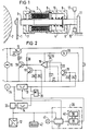
- the plunger magnet system consists essentially of an excitation coil 3 and the plunger armature 4 serving as a drive element for the type wheel 1.
- the plunger armature 4 has two non-magnetic guide parts 5 and 6 which, together with bushings 7 and 8, prevent the plunger armature from reaching the surface 9 of the excitation coil radially 3 is pulled and thus prevented from its actual axial movement.
- the submersible armature 4 protrudes with its rear part through the bushing 8 and rests against a stop 11 under the action of a return spring 10 in the idle state.
- a sensor 12 in this case a photoelectric switching device, is made of a Infrared light barrier, the photo path being arranged in the range of movement of the submersible anchor 4.
- the plunger armature magnet is controlled via a control circuit arrangement which, for. B. can be carried out according to the block diagram of FIG. 2. It essentially consists of two flip-flops 13 and 14 for timing the circuit arrangement. Switching transistors 15, 16 and 17 connect the magnet coil 3 to a constant voltage source 19 as a function of the output signal of an amplifier 18, which regulates the excitation current with imprint and the braking current in the coil 3.
- the amplifier 18, which is connected as a current regulator, is also connected its positive output at a voltage divider consisting of resistors 20 to 24 and the associated switching transistor 25. Resistor 20 is designed as a potentiometer.
- the negative input of the amplifier 18 is connected to a measuring resistor 27 for determining the actual value of the current in the coil 3.
- the other resistors 28 to 32 are used in a known manner to adapt the switching transistors.
- the monostable flip-flop 14 is linked to the output of the photoelectric switching device 12 via a delay element 33.
- the circuit arrangement is controlled via a z. B. Triggered by a keyboard, not shown here, pulse 34.
- the flip-flops 13 and 14 are connected via an OR gate 35 to the control input of the switching transistor 17.
- the drive device has an armature control device 36. It contains a measuring element 27 linked to the pulse input 34 and the sensor 12 and a comparison control device 30 provided with a memory 38 and a comparator 39, the output of which is connected to the reset input of the flip-flop 13.
- a z. B. designed as a warning lamp function warning device 41 is linked to the time measuring element 37. Their function will be explained later. The same applies to the measuring element 42 required for the basic setting of the impression energy after the immersion armature magnet system has been installed in the pressure device.
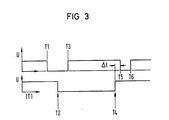
- the immersion anchor detection system shown in FIG. 1 is explained below with reference to FIG. 2 and the voltage-time diagram of FIG. 3. 3, the upper pulse train shows the course of the excitation pulses at the output of the OR gate 35 and the lower pulse train shows the course of the excitation pulses at the output of the sensor 12.
- flip-flop 13 is set via the start pulse input at input 34 and the control path of transistors 17 and 25 is thus interrupted via OR gate 35. This makes the current control device effective.
- the switching transistor 16 and the power transistor 15 become conductive, as a result of which the current in the excitation coil 3 increases suddenly up to the maximum value determined by the control device.
- the armature 4 is accelerated under the effect of the generated magnetic field.
- the time measuring element 37 of the armature control device 36 begins, which, for. B. can be designed as a counter, its operation.
- the light barrier opens and a rectangular pulse with a falling edge occurs at the output of sensor 12. This rectangular pulse stops the time measuring element 37 and the result of the measurement is fed to a comparison control device 40.
- This comparison control device 40 can e.g. B. be designed as a microprocessor and contains a memory 38 with associated central control unit 39.
- the path per unit of time running from the anchor from the stop to the light cabinets is a measure of the pressure energy applied. If the throughput time determined by the time measuring element 37 differs from the target time stored in the memory 38, then the central unit 39 controls accordingly the resetting of the flip-flop 13 at the time T3. At time T3, the flip-flop 13 is returned to its original position. The transistors 17 and 25 thus become conductive again, the current regulation being interrupted and the power transistor 15 being switched off. The armature control device 36 thus controls the time length of the activation of the transistor 15 and thus the excitation current in the coil 3 via the flip-flop 13.
- the output signal of the sensor 12 delayed by the time A via the timing element 33 activates the monostable flip-flop 14 that can be set with a rising pulse edge which interrupts the switching transistor 17 again via the OR gate 35 at the time T5 and thus activates the coil 3.
- the switching transistor 25 is in the conductive state because of the flip-flop 13, so that the amplifier 18 regulates the excitation current in the coil 3 to a lower braking current in this case.
- the armature 4 is completely braked by this braking current and can lay down against the stop 11 without reverberation.
- the monostable multivibrator 14 tilts back into its original position, which makes the transistor 17 conductive again and thus interrupts the excitation current in the coil 3 via the power transistor 17.
- Another impression cycle can be started by a new start pulse 35.
- the circuit arrangement is also equipped with a function warning device 41.
- This function warning device is connected, for example, to the time measuring element 37 and then emits a warning signal if not within a certain period of time after the start of the
- Submersible magnet system passes the end of the armature 4, the light barrier 12.
- Exceeding this time period indicates a malfunction of the plunger magnet system.
- This can e.g. B. a break in the armature or a defect in the excitation coil.
- the function warning device itself can consist of a comparator which compares the counter reading of the time measuring element 37 with a stored target value and activates a warning device when exceeded.
- the basic setting of the impression energy can be accomplished in a simple manner after the plunger magnet system has been installed in the pressure device.
- the control circuit arrangement has a potentiometer 20, by means of which the maximum excitation current in the coil 3 can be set.
- a measuring element 42 can be coupled to the output of the sensor 12.
- B. can consist of a time measuring device with associated display device, via which the throughput time of the armature is measured from the initial interruption of the light barrier to the interruption of the light barrier when the armature returns to the starting position.
- This lead time of the armature is a measure of the impression energy and with the basic setting of the immersion armature magnet system after installation in the pressure seal, this time can be compared with a predetermined target time and a basic setting of the excitation current in the coil 3 can be made by changing the potentiometer 20.
- the design of the drive device is not limited to the example shown. Other embodiments are also conceivable for the individual elements.
- the sensor 12 can e.g. can also be an element that detects the movement of the armature by induction, or two sensors can be arranged in the armature path.
Landscapes
- Physics & Mathematics (AREA)
- Electromagnetism (AREA)
- Impact Printers (AREA)
Claims (7)
Applications Claiming Priority (2)
| Application Number | Priority Date | Filing Date | Title |
|---|---|---|---|
| DE3116430 | 1981-04-24 | ||
| DE19813116430 DE3116430C2 (de) | 1981-04-24 | 1981-04-24 | Hammerdruckvorrichtung mit einem einen optoelektronischen Sensor enthaltenden Tauchankermagnetsystem |
Publications (3)
| Publication Number | Publication Date |
|---|---|
| EP0063784A2 EP0063784A2 (fr) | 1982-11-03 |
| EP0063784A3 EP0063784A3 (en) | 1985-01-09 |
| EP0063784B1 true EP0063784B1 (fr) | 1987-07-01 |
Family
ID=6130796
Family Applications (1)
| Application Number | Title | Priority Date | Filing Date |
|---|---|---|---|
| EP19820103372 Expired EP0063784B1 (fr) | 1981-04-24 | 1982-04-21 | Dispositif d'impression par marteaux avec un système d'électro-aimants à plongeur comportant un détecteur électro-optique |
Country Status (2)
| Country | Link |
|---|---|
| EP (1) | EP0063784B1 (fr) |
| DE (1) | DE3116430C2 (fr) |
Families Citing this family (3)
| Publication number | Priority date | Publication date | Assignee | Title |
|---|---|---|---|---|
| US4547087A (en) * | 1983-01-20 | 1985-10-15 | Siemens Aktiengesellschaft | Microprocessor-controlled printing mechanism having an opto-electronic sensor |
| DE3346133A1 (de) * | 1983-12-21 | 1985-07-04 | Ibm Deutschland Gmbh, 7000 Stuttgart | Automatische flugzeitmessung in anschlagdruckern |
| US4678355A (en) * | 1985-07-02 | 1987-07-07 | Xerox Corporation | Print tip contact sensor for quiet impact printer |
Family Cites Families (5)
| Publication number | Priority date | Publication date | Assignee | Title |
|---|---|---|---|---|
| FR2130804A5 (fr) * | 1971-02-23 | 1972-11-10 | Nortec Computer Devices | |
| AU521251B2 (en) * | 1977-09-14 | 1982-03-25 | Exxon Research And Engineering Company | Hammer for impact printer |
| DE2933616C2 (de) * | 1979-08-20 | 1982-09-23 | Siemens AG, 1000 Berlin und 8000 München | Dämpfungsvorrichtung für einen als Klappankermagnetsystem ausgebildeten elektromagnetischen Antrieb für den Druckhammer in einer Druckhammeranordnung |
| US4347786A (en) * | 1979-10-01 | 1982-09-07 | International Business Machines Corporation | Impact printer hammer flight time and velocity sensing means |
| US4429342A (en) * | 1981-04-24 | 1984-01-31 | Siemens Aktiengesellschaft | Impact printing device with an improved print hammer |
-
1981
- 1981-04-24 DE DE19813116430 patent/DE3116430C2/de not_active Expired
-
1982
- 1982-04-21 EP EP19820103372 patent/EP0063784B1/fr not_active Expired
Also Published As
| Publication number | Publication date |
|---|---|
| DE3116430C2 (de) | 1983-03-31 |
| EP0063784A2 (fr) | 1982-11-03 |
| EP0063784A3 (en) | 1985-01-09 |
| DE3116430A1 (de) | 1982-11-18 |
Similar Documents
| Publication | Publication Date | Title |
|---|---|---|
| DE2847492C2 (de) | Schaltungsanordnung in einem Druckwerk mit einer Stoßvorrichtung | |
| DE69028802T2 (de) | Erfassung des Einschaltens einer Spule | |
| DE2629096C3 (de) | Steuerschaltung für einen Schrittmotor | |
| DE2602906C2 (fr) | ||
| DE2928304C2 (de) | Steuerschaltung zum Aufrechterhalten einer konstanten Farbintensität bei einer thermischen Aufzeichnungsvorrichtung | |
| EP0064632B1 (fr) | Dispositif de marteau imprimant | |
| EP0116850B1 (fr) | Système d'impression avec induit plongeur commandé par microprocesseur et contenant un détecteur opto-électronique | |
| DE2908235C2 (de) | Vorrichtung an einer Einspritzpumpe mit einer Regelstange zur Einstellung der Fördermenge von Brennstoff für den Betrieb einer Brennkraftmaschine | |
| DE3036919C2 (de) | Druckhammerantieb für einen Punktmatrixdrucker | |
| DE3727283C2 (fr) | ||
| EP0063784B1 (fr) | Dispositif d'impression par marteaux avec un système d'électro-aimants à plongeur comportant un détecteur électro-optique | |
| DE69512545T2 (de) | Optischer Trigger für eine Frankiermaschine | |
| DE3329800C2 (fr) | ||
| DE69003975T2 (de) | Vorrichtung zur automatischen Druckspalteinstellung für einen Druckkopf. | |
| DE2848786C3 (de) | Schaltungsanordnung für die Synchronisierung der Auftrittszeitpunkte von Druckhammeraufschlag mit dem Eintreffen der Drucktype an der Druckstelle | |
| DE3116402C2 (de) | Rückprallarmes Tauchankermagnetsystem | |
| DE2648828C3 (de) | Vorrichtung zum Betätigen von Elektromagneten | |
| DE2511260C3 (de) | Schaltungsanordnung in einer Strickmaschine | |
| DE2404799C2 (de) | Steuerschaltung für die Ausrichtung von Druckhämmern in Schnelldruckern | |
| DE3739295C1 (de) | Verfahren zur Rueckpralldaempfung bei Druckhammermagneten in Schreib- oder aehnlichen Bueromaschinen | |
| DE2013413A1 (fr) | ||
| EP0406236B1 (fr) | Dispositif de controle du transport de supports d'enregistrement en feuilles dans une machine d'impression par electrophotographie | |
| DE3001908C2 (de) | Einrichtung zur Messung des Drehwinkels einer Welle einer Maschine | |
| DE3919310C2 (fr) | ||
| DE3805081A1 (de) | Elektromagnetische antriebsschaltung |
Legal Events
| Date | Code | Title | Description |
|---|---|---|---|
| PUAI | Public reference made under article 153(3) epc to a published international application that has entered the european phase |
Free format text: ORIGINAL CODE: 0009012 |
|
| AK | Designated contracting states |
Designated state(s): CH FR GB IT NL SE |
|
| PUAL | Search report despatched |
Free format text: ORIGINAL CODE: 0009013 |
|
| AK | Designated contracting states |
Designated state(s): CH FR GB IT LI NL SE |
|
| 17P | Request for examination filed |
Effective date: 19841213 |
|
| GRAA | (expected) grant |
Free format text: ORIGINAL CODE: 0009210 |
|
| AK | Designated contracting states |
Kind code of ref document: B1 Designated state(s): CH FR GB IT LI NL SE |
|
| ET | Fr: translation filed | ||
| ITF | It: translation for a ep patent filed | ||
| PG25 | Lapsed in a contracting state [announced via postgrant information from national office to epo] |
Ref country code: GB Effective date: 19880421 |
|
| PG25 | Lapsed in a contracting state [announced via postgrant information from national office to epo] |
Ref country code: LI Effective date: 19880430 Ref country code: CH Effective date: 19880430 |
|
| PLBE | No opposition filed within time limit |
Free format text: ORIGINAL CODE: 0009261 |
|
| STAA | Information on the status of an ep patent application or granted ep patent |
Free format text: STATUS: NO OPPOSITION FILED WITHIN TIME LIMIT |
|
| 26N | No opposition filed | ||
| PG25 | Lapsed in a contracting state [announced via postgrant information from national office to epo] |
Ref country code: NL Effective date: 19881101 |
|
| NLV4 | Nl: lapsed or anulled due to non-payment of the annual fee | ||
| GBPC | Gb: european patent ceased through non-payment of renewal fee | ||
| PG25 | Lapsed in a contracting state [announced via postgrant information from national office to epo] |
Ref country code: FR Free format text: LAPSE BECAUSE OF NON-PAYMENT OF DUE FEES Effective date: 19881229 |
|
| REG | Reference to a national code |
Ref country code: CH Ref legal event code: PL |
|
| REG | Reference to a national code |
Ref country code: FR Ref legal event code: ST |
|
| PGFP | Annual fee paid to national office [announced via postgrant information from national office to epo] |
Ref country code: SE Payment date: 19890428 Year of fee payment: 8 |
|
| ITTA | It: last paid annual fee | ||
| PG25 | Lapsed in a contracting state [announced via postgrant information from national office to epo] |
Ref country code: SE Effective date: 19900422 |
|
| EUG | Se: european patent has lapsed |
Ref document number: 82103372.7 Effective date: 19910115 |