EP0063838A1 - Tête d'impression pour imprimantes à jet d'encre et procédé pour sa fabrication - Google Patents
Tête d'impression pour imprimantes à jet d'encre et procédé pour sa fabrication Download PDFInfo
- Publication number
- EP0063838A1 EP0063838A1 EP82200450A EP82200450A EP0063838A1 EP 0063838 A1 EP0063838 A1 EP 0063838A1 EP 82200450 A EP82200450 A EP 82200450A EP 82200450 A EP82200450 A EP 82200450A EP 0063838 A1 EP0063838 A1 EP 0063838A1
- Authority
- EP
- European Patent Office
- Prior art keywords
- bundle
- tubes
- alignment plates
- jet nozzle
- situated
- Prior art date
- Legal status (The legal status is an assumption and is not a legal conclusion. Google has not performed a legal analysis and makes no representation as to the accuracy of the status listed.)
- Granted
Links
- 238000007639 printing Methods 0.000 title claims abstract description 34
- 238000000034 method Methods 0.000 title claims description 19
- 238000004519 manufacturing process Methods 0.000 title claims description 11
- 230000008878 coupling Effects 0.000 claims abstract description 36
- 238000010168 coupling process Methods 0.000 claims abstract description 36
- 238000005859 coupling reaction Methods 0.000 claims abstract description 36
- 239000011521 glass Substances 0.000 claims abstract description 12
- 239000000206 moulding compound Substances 0.000 claims abstract description 6
- 238000005086 pumping Methods 0.000 claims description 34
- 238000000465 moulding Methods 0.000 claims description 12
- 238000010438 heat treatment Methods 0.000 abstract description 2
- 239000000463 material Substances 0.000 description 5
- 239000004033 plastic Substances 0.000 description 4
- 229920003023 plastic Polymers 0.000 description 4
- 238000000926 separation method Methods 0.000 description 3
- 239000000853 adhesive Substances 0.000 description 2
- 230000001070 adhesive effect Effects 0.000 description 2
- 238000010924 continuous production Methods 0.000 description 2
- 239000011159 matrix material Substances 0.000 description 2
- OSGAYBCDTDRGGQ-UHFFFAOYSA-L calcium sulfate Inorganic materials [Ca+2].[O-]S([O-])(=O)=O OSGAYBCDTDRGGQ-UHFFFAOYSA-L 0.000 description 1
- ZOMBKNNSYQHRCA-UHFFFAOYSA-J calcium sulfate hemihydrate Chemical compound O.[Ca+2].[Ca+2].[O-]S([O-])(=O)=O.[O-]S([O-])(=O)=O ZOMBKNNSYQHRCA-UHFFFAOYSA-J 0.000 description 1
- 239000000919 ceramic Substances 0.000 description 1
- 238000006073 displacement reaction Methods 0.000 description 1
- 239000011507 gypsum plaster Substances 0.000 description 1
- 238000002844 melting Methods 0.000 description 1
- 230000008018 melting Effects 0.000 description 1
- 239000002184 metal Substances 0.000 description 1
- 229910052751 metal Inorganic materials 0.000 description 1
- 150000002739 metals Chemical class 0.000 description 1
- 238000005498 polishing Methods 0.000 description 1
- 230000001681 protective effect Effects 0.000 description 1
- 238000006748 scratching Methods 0.000 description 1
- 230000002393 scratching effect Effects 0.000 description 1
- 238000013022 venting Methods 0.000 description 1
Images

Classifications
-
- B—PERFORMING OPERATIONS; TRANSPORTING
- B41—PRINTING; LINING MACHINES; TYPEWRITERS; STAMPS
- B41J—TYPEWRITERS; SELECTIVE PRINTING MECHANISMS, i.e. MECHANISMS PRINTING OTHERWISE THAN FROM A FORME; CORRECTION OF TYPOGRAPHICAL ERRORS
- B41J2/00—Typewriters or selective printing mechanisms characterised by the printing or marking process for which they are designed
- B41J2/005—Typewriters or selective printing mechanisms characterised by the printing or marking process for which they are designed characterised by bringing liquid or particles selectively into contact with a printing material
- B41J2/01—Ink jet
- B41J2/135—Nozzles
- B41J2/16—Production of nozzles
- B41J2/1621—Manufacturing processes
- B41J2/1632—Manufacturing processes machining
-
- B—PERFORMING OPERATIONS; TRANSPORTING
- B29—WORKING OF PLASTICS; WORKING OF SUBSTANCES IN A PLASTIC STATE IN GENERAL
- B29C—SHAPING OR JOINING OF PLASTICS; SHAPING OF MATERIAL IN A PLASTIC STATE, NOT OTHERWISE PROVIDED FOR; AFTER-TREATMENT OF THE SHAPED PRODUCTS, e.g. REPAIRING
- B29C33/00—Moulds or cores; Details thereof or accessories therefor
- B29C33/0033—Moulds or cores; Details thereof or accessories therefor constructed for making articles provided with holes
-
- B—PERFORMING OPERATIONS; TRANSPORTING
- B41—PRINTING; LINING MACHINES; TYPEWRITERS; STAMPS
- B41J—TYPEWRITERS; SELECTIVE PRINTING MECHANISMS, i.e. MECHANISMS PRINTING OTHERWISE THAN FROM A FORME; CORRECTION OF TYPOGRAPHICAL ERRORS
- B41J2/00—Typewriters or selective printing mechanisms characterised by the printing or marking process for which they are designed
- B41J2/005—Typewriters or selective printing mechanisms characterised by the printing or marking process for which they are designed characterised by bringing liquid or particles selectively into contact with a printing material
- B41J2/01—Ink jet
- B41J2/135—Nozzles
- B41J2/16—Production of nozzles
- B41J2/1607—Production of print heads with piezoelectric elements
- B41J2/1615—Production of print heads with piezoelectric elements of tubular type
-
- B—PERFORMING OPERATIONS; TRANSPORTING
- B41—PRINTING; LINING MACHINES; TYPEWRITERS; STAMPS
- B41J—TYPEWRITERS; SELECTIVE PRINTING MECHANISMS, i.e. MECHANISMS PRINTING OTHERWISE THAN FROM A FORME; CORRECTION OF TYPOGRAPHICAL ERRORS
- B41J2/00—Typewriters or selective printing mechanisms characterised by the printing or marking process for which they are designed
- B41J2/005—Typewriters or selective printing mechanisms characterised by the printing or marking process for which they are designed characterised by bringing liquid or particles selectively into contact with a printing material
- B41J2/01—Ink jet
- B41J2/135—Nozzles
- B41J2/16—Production of nozzles
- B41J2/1621—Manufacturing processes
- B41J2/1637—Manufacturing processes molding
-
- B—PERFORMING OPERATIONS; TRANSPORTING
- B29—WORKING OF PLASTICS; WORKING OF SUBSTANCES IN A PLASTIC STATE IN GENERAL
- B29L—INDEXING SCHEME ASSOCIATED WITH SUBCLASS B29C, RELATING TO PARTICULAR ARTICLES
- B29L2031/00—Other particular articles
- B29L2031/767—Printing equipment or accessories therefor
Definitions
- the invention relates to a method of manufacturing printing heads for ink jet printers, which comprises moulding of coupling pieces through each of which jet nozzle ducts extend from a rear portion of the coupling piece to a front portion thereof, said jet nozzle ducts being situated nearer to one another in the front portion of the coupling piece than in the rear portion, and arranging a cylindrical pumping member around each jet nozzle duct near the rear portion of the coupling piece.
- the invention also relates'to a printing head manufactured by such a method.
- a printing head of this kind is known from German Auslegeschrift 25 43 420.
- the invention has for its object to provide a method of manufacturing such printing heads which is very simple and quick and whereby substantial parts of at least two printing heads can be manufactured simultaneously.
- the method in accordance with the invention is characterized in that the tubes of a bundle of parallel glass tubes are passed through openings in parallel alignment plates, the openings in each plate being arranged in a pattern-which corresponds to the desired arrangement of the jet nozzle ducts at the rear of each coupling piece to be formed, and the alignment plates dividing the bundle into a central portion which extends in a zone between the two alignment plates and two end portions which are situated outside this zone and each of which has a length at least equal to the length of the pumping members, after which the tubes are softened by heat and the central portion of the bundle is constricted until halfway between the two alignment plates the tubes become disposed in a pattern which corresponds to the desired arrangement of the jet nozzle ducts at the front of each coupling piece to be formed, after which at least the central portion of the bundle is embedded in a moulding compound which, when
- the coupling pieces for two printing heads are formed simultaneously, the coupling pieces being initially interconnected at their front ends and subsequently being separated.
- One version of the method in accordance with the invention is characterized in that the tubes in at least one of the end portions of the bundle integrally - adjoin the tubes in an end portion of a further bundle of parallel glass tubes passed through openings in parallel alignment plates, these two end portions subsequently being separated from one another along a separating plane which extends parallel to the alignment plates and is situated at a distance from each of the two alignment plates bounding said two end portions of the tube bundles which at least equals the length of the pumping members.
- a printing head in accordance with the invention is characterized in that an alignment plate is arranged between the coupling piece and the pumping section.
- the printing head which is shown in Fig. 1 comprises a coupling piece 1 which is made of a moulding compound and through which jet nozzle ducts 3 extend.
- the moulding compound is preferably a plastics material but other materials such as plaster of Paris and metals having a low melting point are also suitable.
- Each jet nozzle duct 3 extends from a rear end of the coupling piece 1 at the left in Fig. 1) to a front end (at the right in Fig. 1).
- the jet nozzle ducts 3 are situated nearer to one another in the front portion of the coupling piece than in the rear portion.
- each jet nozzle duct 3 continues into a pumping section 7 which is situated behind the alignment plate 5 and in which each jet nozzle duct is surrounded by a cylindrical pumping member 9.
- Each pumping member 9 may. consist of a piezoelectric ceramic tube which comprises electrodes on its inner and outer walls and which is secured to the jet nozzle duct 3 by means of an adhesive. Pumping members of this kind are known, for example, from US Patent Specification 3,832,579.
- each jet nozzle duct 3 which extends through the rear portion 13 comprises a constriction 15.
- the pumping section 7 and the rear portion 13 are also moulded in, for example, a plastics material.
- connection piece 16 which contains an ink supply duct 17 which communicates with the rear openings of the jet nozzle ducts 3.
- the ink supply duct 17 can be connected to an ink reservoir (not shown) via a tube 19 and can be vented via a venting device 21.
- jet nozzle plate 23 which comprises jet nozzles 25 into which the jet nozzle ducts 3 open at their front ends.
- the operation of the above-described printing head is known per se, so it will only be briefly described herein.
- the jet nozzle ducts 3 are filled with ink.
- one of the pumping members 9 is actuated, a pressure wave is formed in the associated jet nozzle duct. Due to the constriction 15, the ink displacement occurring in the duct due to this pressure wave cannot be directed backwards, so that part of the ink is displaced forwards and escapes as an ejecteddroplet via the associated jet nozzle 25.
- This droplet is directed onto a sheet of paper arranged in front of the printing head, and forms, for example, an element of a character.
- the jet nozzles 25 are arranged, for example, in a matrix of six rows and four columns.
- the jet nozzles may be arranged in one column, the printing head then being intermittently displaced in operation in a direction perpendicular to said column in order to form a character.
- Fig. 2 shows the glass tubes 27 arranged parallel to one another in a bundle, for which purpose they are passed through openings 29 in two alignment plates 5 are arranged parallel to and at a distance from one another.
- Fig. 3 is a front view of one of the alignment plates 5, showing the openings 29. These openings are f arranged in a matrix of six rows and four columns corresponding to the desired arrangement of the jet nozzle ducts 3 at the rear of each coupling piece 1 to be formed.
- the two alignment plates 5 divide the bundle of glass tubes 27 into a central portion 31 which extends between the two alignment plates and two end portions 33 which are situated beyond the alignment plates.
- the two end portions 33 each have a limited length which at least equals the length of the pumping members 9 but which need not be much larger.
- the tubes 27 are softened by heating them beyond the softening point of the glass, and the central portion of the bundle is then constricted by means of a suitable tool until halfway between the two alignment plates 5 the tubes become disposed in a pattern which corresponds substantially to the desired arrangement of the jet nozzle ducts 3 at the front of each coupling piece to be formed, and hence also to the arrangement of the jet.nozzles 25.
- This pattern will usually be a facsimile to a reduced scale of the pattern of the openings 29 in the alignment plates 5 shown in Fig. 3.
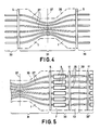
- Fig. 4 The result of the constriction of the central portion 31 of the tube bundle is shown in Fig. 4.
- the constricted central portion 31 is subsequently embedded in a plastics material in a suitable mould so that a moulding 35 is obtained (outlined in dot-dash lines).
- This moulding forms two coupling pieces 1 which are separated from one another, after the setting of the plastics material, along a separating plane 37.
- the separating plane extends parallel to the two alignment plates 5 and is situated halfway between them. Separation can be effected by, for example, through the moulding 35 and the tubes 27 along the plane 37 or by scratching a groove around the circumference of the moulding 35 in the plane 37 and then breaking the moulding and the tubes in this plane.
- the surfaces formed by the separation can subsequently be finished, if necessary, for example, by polishing. Jet nozzle plates 23 can be fixed on these surfaces, for example, by means of an adhesive.
- the portions of the tubes 27 which are situated in the end portions 33 of the bundle of tubes are subsequently provided with the pumping members 9. Behind these pumping members constrictions 15 can be formed in the tubes, but it is alternatively possible to connect to the near ends of the tubes 27 further tubes, for example, rubber tubes, in which the constrictions have been preformed.
- the printing head, or at least the portion thereof which is situated behind the alignment plate 5, can subsequently be arranged in a protective housing (not shown).
- Fig. 5 is a side elevation of a bundle of glass tubes 27 after the constriction of the central portion 31 of the bundle.
- the bundle is the first of a continuous succession of tube bundles formed of continuous glass tubes, so that the tubes in the right end portion 33 of the first bundle integrally adjoin the tubes in the left end portion 33 1 of the next bundle.
- the manufacturing process may then be continuous in that the tubes 27 are moved to the left .
- the moulding and tube bundle are then divided along the plane 37, and subsequently the right end portion 33 of the bundle is separated from the adjoining left end portion 33' of the next tube bundle along a plane 39 which extends parallel to the alignment plates 5 and is situated midway between the two alignment plates which bound the adjoining end portions 33 and 33' of the two adjoining tube bundles.
- the distance between the plane 39 and each of these two alignment plates 5 must be at least equal to the length of the pumping members 9.
- this distance can be large enough to allow not only the portions of the jet nozzle ducts 3 which are situated within the pumping section 7 of the printing head but also the portions which are situated in the rear portion 13 of the printing head to be formed from the tubes 27 so as to be integral with the portions of the ducts which are situated within the coupling piece 1.
- the portions of the tubes which are situated in the end portions 33 of the bundle are each formed with a constriction 15 at a distance from the nearer alignment plate 5 which is larger than the length of the pumping members 9.
- the tubes in each end portion are preferably passed through openings in an end plate 11 which is arranged parallel to the alignment plates 5.
- the distance between each end plate 11 and the nearer alignment plate 5 must be at least equal to the length of the pumping members 9.
- the openings in each end plate 11 are arranged in a pattern which is similar to that of the openings 29 in each alignment plate 5 (see Fig. 3). If desired, the two patterns may be completely identical.
- An example of the continuous process for the manufacture of the printing heads is as follows.
- the front ends of the tubes 27 are passed successively through a first end plate 11, a first group of pumping members 9, a first alignment plate 5, a second alignment plate 5, a second group of pumping members 9 and a second end plate 11 to form a first bundle of tubes.
- the central portion 31 of this bundle of tubes is subsequently constricted and constrictions 15 are formed in those portions of the tubes which are located in the end portions 33 of the bundle, outside the end plates 11.
- the moulding 35 is formed.
- the moulding may extend from the front ends of the tubes 27 as far as the location of the separating plane 39 between the first tube bundle and the next tube bundle.
- the method in accordance with the invention offers a large range of possibilities from the simple manufacture of coupling pieces two at a time followed by the individual mounting of the end plates, alignment plates and pumping members, up to and including the continuous manufacture of an arbitrary number of substantially complete printing heads.
Landscapes
- Engineering & Computer Science (AREA)
- Manufacturing & Machinery (AREA)
- Mechanical Engineering (AREA)
- Particle Formation And Scattering Control In Inkjet Printers (AREA)
- Ink Jet (AREA)
Applications Claiming Priority (2)
| Application Number | Priority Date | Filing Date | Title |
|---|---|---|---|
| NL8102026 | 1981-04-24 | ||
| NL8102026A NL8102026A (nl) | 1981-04-24 | 1981-04-24 | Werkwijze voor het vervaardigen van schrijfkoppen voor inktstraaldrukkers en schrijfkop vervaardigd volgens die werkwijze. |
Publications (2)
| Publication Number | Publication Date |
|---|---|
| EP0063838A1 true EP0063838A1 (fr) | 1982-11-03 |
| EP0063838B1 EP0063838B1 (fr) | 1984-08-15 |
Family
ID=19837403
Family Applications (1)
| Application Number | Title | Priority Date | Filing Date |
|---|---|---|---|
| EP82200450A Expired EP0063838B1 (fr) | 1981-04-24 | 1982-04-14 | Tête d'impression pour imprimantes à jet d'encre et procédé pour sa fabrication |
Country Status (6)
| Country | Link |
|---|---|
| US (1) | US4421706A (fr) |
| EP (1) | EP0063838B1 (fr) |
| JP (1) | JPS57182453A (fr) |
| CA (1) | CA1180944A (fr) |
| DE (1) | DE3260572D1 (fr) |
| NL (1) | NL8102026A (fr) |
Families Citing this family (6)
| Publication number | Priority date | Publication date | Assignee | Title |
|---|---|---|---|---|
| US6053598A (en) * | 1995-04-13 | 2000-04-25 | Pitney Bowes Inc. | Multiple print head packaging for ink jet printer |
| US5901425A (en) * | 1996-08-27 | 1999-05-11 | Topaz Technologies Inc. | Inkjet print head apparatus |
| TW514596B (en) * | 2000-02-28 | 2002-12-21 | Hewlett Packard Co | Glass-fiber thermal inkjet print head |
| US7163284B2 (en) * | 2001-12-12 | 2007-01-16 | Industrial Technology Research Institute | Multi-reagent inkjet cartridge |
| US6752490B2 (en) * | 2002-03-07 | 2004-06-22 | David J. Pickrell | Micro fluid dispensers using flexible hollow glass fibers |
| WO2009155245A1 (fr) * | 2008-06-17 | 2009-12-23 | Davicon Corporation | Appareil de distribution de liquide utilisant un procédé passif de dosage de liquide |
Citations (4)
| Publication number | Priority date | Publication date | Assignee | Title |
|---|---|---|---|---|
| US4112436A (en) * | 1977-02-24 | 1978-09-05 | The Mead Corporation | Glass nozzle array for an ink jet printer and method of forming same |
| US4216477A (en) * | 1978-05-10 | 1980-08-05 | Hitachi, Ltd. | Nozzle head of an ink-jet printing apparatus with built-in fluid diodes |
| GB2053097A (en) * | 1979-07-07 | 1981-02-04 | Philips Nv | Ink jet printer |
| DE2930004A1 (de) * | 1979-07-24 | 1981-03-12 | Siemens AG, 1000 Berlin und 8000 München | Piezoelektrisches antriebselement fuer schreibkoepfe in tintenmosaikschreibeinrichtungen. |
Family Cites Families (10)
| Publication number | Priority date | Publication date | Assignee | Title |
|---|---|---|---|---|
| US2608722A (en) * | 1950-09-06 | 1952-09-02 | Otmar M Stuetzer | Process for making microspacers |
| US3043910A (en) * | 1958-05-19 | 1962-07-10 | American Optical Corp | Fiber optical image transfer devices |
| US3157721A (en) * | 1959-12-07 | 1964-11-17 | Burroughs Corp | Method and apparatus for positioning and assembling wires and the like |
| BE632088A (fr) * | 1962-05-09 | |||
| US3853658A (en) * | 1971-07-12 | 1974-12-10 | R Ney | Fiber optical image magnifier panel and method of manufacture |
| JPS5315030B2 (fr) * | 1972-05-12 | 1978-05-22 | ||
| US3832579A (en) * | 1973-02-07 | 1974-08-27 | Gould Inc | Pulsed droplet ejecting system |
| DE2543420C3 (de) * | 1975-09-29 | 1980-09-11 | Siemens Ag, 1000 Berlin Und 8000 Muenchen | Piezoelektrisches Antriebselement für Schreibköpfe in Tintenmosaik-Schreibeinrichtungen |
| JPS5590426A (en) * | 1978-12-26 | 1980-07-09 | Canon Inc | Forming method for nozzle |
| JPS55103971A (en) * | 1979-02-06 | 1980-08-08 | Canon Inc | Recording head |
-
1981
- 1981-04-24 NL NL8102026A patent/NL8102026A/nl not_active Application Discontinuation
-
1982
- 1982-03-19 US US06/359,644 patent/US4421706A/en not_active Expired - Fee Related
- 1982-03-31 CA CA000400007A patent/CA1180944A/fr not_active Expired
- 1982-04-14 EP EP82200450A patent/EP0063838B1/fr not_active Expired
- 1982-04-14 DE DE8282200450T patent/DE3260572D1/de not_active Expired
- 1982-04-21 JP JP57065556A patent/JPS57182453A/ja active Pending
Patent Citations (4)
| Publication number | Priority date | Publication date | Assignee | Title |
|---|---|---|---|---|
| US4112436A (en) * | 1977-02-24 | 1978-09-05 | The Mead Corporation | Glass nozzle array for an ink jet printer and method of forming same |
| US4216477A (en) * | 1978-05-10 | 1980-08-05 | Hitachi, Ltd. | Nozzle head of an ink-jet printing apparatus with built-in fluid diodes |
| GB2053097A (en) * | 1979-07-07 | 1981-02-04 | Philips Nv | Ink jet printer |
| DE2930004A1 (de) * | 1979-07-24 | 1981-03-12 | Siemens AG, 1000 Berlin und 8000 München | Piezoelektrisches antriebselement fuer schreibkoepfe in tintenmosaikschreibeinrichtungen. |
Also Published As
| Publication number | Publication date |
|---|---|
| NL8102026A (nl) | 1982-11-16 |
| JPS57182453A (en) | 1982-11-10 |
| US4421706A (en) | 1983-12-20 |
| EP0063838B1 (fr) | 1984-08-15 |
| DE3260572D1 (en) | 1984-09-20 |
| CA1180944A (fr) | 1985-01-15 |
Similar Documents
| Publication | Publication Date | Title |
|---|---|---|
| EP0430692B1 (fr) | Méthode de fabrication de tête d'impression | |
| EP0339058B1 (fr) | Range de buses de jet d'encre | |
| US5771052A (en) | Single pass ink jet printer with offset ink jet modules | |
| SE454152B (sv) | Metod for framstellning av stralmunstyckskanaler | |
| JP6068684B2 (ja) | 流体流れ構造の成形 | |
| JP3542389B2 (ja) | 平行印刷装置及びその製造方法 | |
| US6779871B1 (en) | Inkjet recording head and inkjet recording device | |
| JP4768195B2 (ja) | 印刷ヘッドモジュールのオーバーラップアレー構成 | |
| US4364067A (en) | Highly integrated ink jet head | |
| US20020051039A1 (en) | Simplified ink jet head | |
| CN1130129A (zh) | 具有内装过滤器结构的喷墨打印头 | |
| US4779099A (en) | Clamp for and method of fabricating a multi-layer ink jet apparatus | |
| GB2090201A (en) | Ink-jet printing head | |
| ATE110028T1 (de) | Tintenstrahlkopf, sein herstellungsverfahren, substrat für einen tintenstrahlkopf, kontrollmethode hierzu und tintenstrahlgerät. | |
| EP0063838B1 (fr) | Tête d'impression pour imprimantes à jet d'encre et procédé pour sa fabrication | |
| US5414916A (en) | Ink jet printhead assembly having aligned dual internal channel arrays | |
| EP0225168B1 (fr) | Appareil à jet d'encre par impulsion | |
| JPH068445A (ja) | インクジェット・プリンタ用プリントヘッド,インクジェット・プリンタ用プリントヘッドの形成方法及び部品組立方法 | |
| US6357867B1 (en) | Single-pass inkjet printing | |
| CA1160905A (fr) | Dispositif pour tete d'impression d'imprimante a mosaique de gicleurs d'encre | |
| EP0921003A1 (fr) | Tête d'impression à jet d'encre | |
| US4447375A (en) | Method of casting a printing head for an ink jet printer | |
| KR100243428B1 (ko) | 잉크 제트 프린트 헤드의 제조방법 | |
| ITTO980592A1 (it) | Testina di stampa a getto di inchiostro con piastrina di silicio di grandi dimensioni e relativo processo di fabbricazione | |
| US6588883B2 (en) | Liquid injector, method of manufacturing the injector, and ink-jet spray using the injector |
Legal Events
| Date | Code | Title | Description |
|---|---|---|---|
| PUAI | Public reference made under article 153(3) epc to a published international application that has entered the european phase |
Free format text: ORIGINAL CODE: 0009012 |
|
| 17P | Request for examination filed |
Effective date: 19820414 |
|
| AK | Designated contracting states |
Designated state(s): DE FR GB IT NL SE |
|
| ITF | It: translation for a ep patent filed | ||
| GRAA | (expected) grant |
Free format text: ORIGINAL CODE: 0009210 |
|
| AK | Designated contracting states |
Designated state(s): DE FR GB IT NL SE |
|
| PG25 | Lapsed in a contracting state [announced via postgrant information from national office to epo] |
Ref country code: NL Effective date: 19840815 |
|
| REF | Corresponds to: |
Ref document number: 3260572 Country of ref document: DE Date of ref document: 19840920 |
|
| ET | Fr: translation filed | ||
| NLV1 | Nl: lapsed or annulled due to failure to fulfill the requirements of art. 29p and 29m of the patents act | ||
| PLBE | No opposition filed within time limit |
Free format text: ORIGINAL CODE: 0009261 |
|
| STAA | Information on the status of an ep patent application or granted ep patent |
Free format text: STATUS: NO OPPOSITION FILED WITHIN TIME LIMIT |
|
| 26N | No opposition filed | ||
| PG25 | Lapsed in a contracting state [announced via postgrant information from national office to epo] |
Ref country code: GB Effective date: 19890414 |
|
| PG25 | Lapsed in a contracting state [announced via postgrant information from national office to epo] |
Ref country code: SE Effective date: 19890415 |
|
| GBPC | Gb: european patent ceased through non-payment of renewal fee | ||
| PG25 | Lapsed in a contracting state [announced via postgrant information from national office to epo] |
Ref country code: FR Free format text: LAPSE BECAUSE OF NON-PAYMENT OF DUE FEES Effective date: 19891228 |
|
| PG25 | Lapsed in a contracting state [announced via postgrant information from national office to epo] |
Ref country code: DE Effective date: 19900103 |
|
| REG | Reference to a national code |
Ref country code: FR Ref legal event code: ST |
|
| EUG | Se: european patent has lapsed |
Ref document number: 82200450.3 Effective date: 19900412 |