EP0063839A2 - Filtres éléctriques passe-bande à ondes acoustiques - Google Patents
Filtres éléctriques passe-bande à ondes acoustiques Download PDFInfo
- Publication number
- EP0063839A2 EP0063839A2 EP82200451A EP82200451A EP0063839A2 EP 0063839 A2 EP0063839 A2 EP 0063839A2 EP 82200451 A EP82200451 A EP 82200451A EP 82200451 A EP82200451 A EP 82200451A EP 0063839 A2 EP0063839 A2 EP 0063839A2
- Authority
- EP
- European Patent Office
- Prior art keywords
- sub
- strips
- frequency
- acoustic wave
- amplitude
- Prior art date
- Legal status (The legal status is an assumption and is not a legal conclusion. Google has not performed a legal analysis and makes no representation as to the accuracy of the status listed.)
- Granted
Links
- 230000004044 response Effects 0.000 claims abstract description 56
- 230000002463 transducing effect Effects 0.000 claims description 18
- 230000008878 coupling Effects 0.000 claims description 12
- 238000010168 coupling process Methods 0.000 claims description 12
- 238000005859 coupling reaction Methods 0.000 claims description 12
- 239000000758 substrate Substances 0.000 claims description 9
- 238000003491 array Methods 0.000 claims description 4
- 238000010897 surface acoustic wave method Methods 0.000 abstract description 18
- APCLRHPWFCQIMG-UHFFFAOYSA-N 4-(5,6-dimethoxy-1-benzothiophen-2-yl)-4-oxobutanoic acid Chemical compound C1=C(OC)C(OC)=CC2=C1SC(C(=O)CCC(O)=O)=C2 APCLRHPWFCQIMG-UHFFFAOYSA-N 0.000 abstract description 8
- 101150092365 MSA2 gene Proteins 0.000 abstract description 8
- 101100240989 Schizosaccharomyces pombe (strain 972 / ATCC 24843) nrd1 gene Proteins 0.000 abstract description 8
- 238000000926 separation method Methods 0.000 description 7
- 238000000034 method Methods 0.000 description 6
- 230000001629 suppression Effects 0.000 description 6
- 238000004458 analytical method Methods 0.000 description 4
- 108010057081 Merozoite Surface Protein 1 Proteins 0.000 description 3
- 230000008901 benefit Effects 0.000 description 3
- 230000001902 propagating effect Effects 0.000 description 3
- 238000005070 sampling Methods 0.000 description 3
- 208000020997 susceptibility to multiple system atrophy 1 Diseases 0.000 description 3
- GQYHUHYESMUTHG-UHFFFAOYSA-N lithium niobate Chemical compound [Li+].[O-][Nb](=O)=O GQYHUHYESMUTHG-UHFFFAOYSA-N 0.000 description 2
- 230000005540 biological transmission Effects 0.000 description 1
- 230000005516 deep trap Effects 0.000 description 1
- 230000001419 dependent effect Effects 0.000 description 1
- 230000003993 interaction Effects 0.000 description 1
- 238000011835 investigation Methods 0.000 description 1
- 230000004048 modification Effects 0.000 description 1
- 238000012986 modification Methods 0.000 description 1
- 239000010453 quartz Substances 0.000 description 1
- VYPSYNLAJGMNEJ-UHFFFAOYSA-N silicon dioxide Inorganic materials O=[Si]=O VYPSYNLAJGMNEJ-UHFFFAOYSA-N 0.000 description 1
Images

Classifications
-
- H—ELECTRICITY
- H03—ELECTRONIC CIRCUITRY
- H03H—IMPEDANCE NETWORKS, e.g. RESONANT CIRCUITS; RESONATORS
- H03H9/00—Networks comprising electromechanical or electro-acoustic elements; Electromechanical resonators
- H03H9/02—Details
- H03H9/02535—Details of surface acoustic wave devices
- H03H9/02637—Details concerning reflective or coupling arrays
- H03H9/02795—Multi-strip couplers as track changers
-
- H—ELECTRICITY
- H03—ELECTRONIC CIRCUITRY
- H03H—IMPEDANCE NETWORKS, e.g. RESONANT CIRCUITS; RESONATORS
- H03H9/00—Networks comprising electromechanical or electro-acoustic elements; Electromechanical resonators
- H03H9/02—Details
- H03H9/125—Driving means, e.g. electrodes, coils
- H03H9/145—Driving means, e.g. electrodes, coils for networks using surface acoustic waves
- H03H9/14544—Transducers of particular shape or position
- H03H9/14552—Transducers of particular shape or position comprising split fingers
Definitions
- the present invention relates to acoustic wave bandpass electrical filters, and in particular to such devices including a track changing multistrip array arranged between input and output transducers on a substrate able to propagate acoustic waves at a surface thereof.
- SAW bandpass electrical filters consist of an input interdigital transducer and an output interdigital transducer with an interposed track changing multistrip array on a high coupling piezoelectric substrate, e.g. Y-Z lithium niobate.
- the combined amplitude-frequency response of the two transducers has a passband which is substantially the desired passband of the filter.
- the major advantage of the multistrip array in these filters is that it provides relative suppression of bulk wave spuriae, and a further advantage is that it allows apodization weighting of both transducers.
- each transducer in these filters has a fundamental passband and further passbands at particular harmonics dependent on the sampling configuration of the transducers, that is to say the centre-to-centre separation period, the electrode polarity sequence and the mark-to-space ratio of the transducer electrodes. If the input and output transducers have different sampling configurations then this may result in suppression of certain of these harmonic passbands in the combined amplitude-frequency response of the filter; this suppression will not occur if the two transducers have the same sampling configuration.
- An interdigital transducer having electrodes with a centre-to-centre separation period of a quarter wavelength of surface acoustic waves at the centre frequency of the fundamental passband known as a double or split electrode transducer, and with an electrode mark-to-space ratio of one-to-one has, as the nearest further passband to the fundamental passband, a third harmonic passband response which is of nearly equal amplitude to that of the fundamental passband.
- a major advantage of the double electrode configuration transducer is that interactions within the transducer which cause undesired ripples in the amplitude-frequency response are minimised, and for this reason it is common to use this configuration for both the input and output transducers.
- the unsuppressed third harmonic response resulting from this use can be a significant disadvantage in certain filter applications.
- this analysis technique is valid in the frequency range approximately 0 to 2f s where f is the mean stopband frequency of the coupler.
- This frequency f s is well known as the frequency at which the centre-to-centre spacing of the strips of a multistrip coupler is half a wavelength of surface acoustic waves.
- This paper proposes that a notch may be put into the frequency response of a forward transfer multistrip coupler by putting a jog into one track. In this case the centre-to-centre strip spacing is d in both tracks, except at the jog in one track where the spacing is d+d
- the third harmonic of a frequency f (wavelength ⁇ o ) d is set to ⁇ o /6.
- figure 5 of this paper shows the theoretically predicted responses for two multistrip couplers, one conventional and one with a third harmonic jog.
- the ratio f o /f s is 0.5 in each case.
- the two responses are shown as broadband responses between 0 and 4f , each with the well-known notch at the frequency f s and the jogged multistrip coupler additionally having a deep trap centred on 3f .
- An object of the invention is to enable the above-mentioned disadvantages of an unsuppressed third harmonic response to be overcome by means which may be used as an alternative or in addition to the jog geometry proposed in the above-described 1980 Ultrasonics Symposium paper.
- the first factor is the realisation that if the analysis in the above-described 1980 Ultrasonics Symposium paper, in which the environment of a single strip within a multistrip coupler is considered to be similar to a single electrode within an interdigital transducer, is extended in the special case where the mark-to-space ratio of the strips is substantially one-to-one, then the wideband frequency response of a single strip imposes a stopband in the amplitude-frequency response of the multistrip coupler between 2f and 4f s .
- the second factor is the realisation that by a suitable choice of the ratio f o /f s , that is to say a choice of the centre-to-centre spacing of the strips relevant to f , this stopband may be used to suppress the third harmonic passband of a surface acoustic wave bandpass filter and the response of the filter over a range of frequencies near that third harmonic passband.
- an acoustic wave bandpass electrical filter including a substrate able to propagate acoustic waves at a surface thereof, input transducing means arranged to launch acoustic wave energy along a first propagation track at said surface, output transducing means arranged to receive acoustic wave energy from a second propagation track at said surface, and electrical coupling means arranged to receive acoustic wave energy from the input transducing means in the first track and to relaunch at least part of that energy as acoustic wave energy towards the output transducing means in the second track, in which the combined amplitude-frequency response of the input and output transducing means has a fundamental passband which is substantially the desired passband of the filter with a maximum amplitude response substantially at a frequency f and has a corresponding third harmonic passband, and in which the coupling means consists of an array of conducting strips across the first track and an array of conducting strips across the second track, the conducting strips of each array being discrete parallel strips electrically
- This configuration of the coupler strips has apparently been adopted as a matter of convenience and therefore no particular attention has apparently been paid to the statement in the well known paper by F.G. Marshall et. al. in IEEE Transactions, Vol. MTT-21, No. 4, April 1973, pages 216 to 225, at page 216 that "a useful rule of thumb is to set the working frequency at approximately three quarters of the stopband frequency".
- the acoustic waves which the substrate is able to propagate at a surface thereof may be conventional surface acoustic waves propagating in the surface of the substrate.
- the acoustic waves may otherwise be, for example, bulk acoustic waves propagating parallel and close to that surface of the substrate; the possible use of this type of bulk acoustic wave is mentioned in connection with delay line feedback oscillators in U.K. Patent Specification No. 1,451,326 and a range of rotated Y-cuts of quartz with propagation perpendicular to the X-axis suitable for this purpose is described in Electronics Letters, 3rd March 1977, Vol. 13, No. 5 at pages 128 to 130.
- the acoustic waves may also otherwise be, for example,piezoelectric leaky surface waves propagating along the X axis of a 41° or 64° rotated Y-cut plane of lithium niobate as described in an article by K. Yamanouchi and K. Shibayama in Journal of Applied Physics, Vol. 43, No. 3, March 1972 at pages 856 to 862.
- FIG. 1 there is shown a substrate SU able to propagate surface acoustic waves at a surface thereof, input transducing means IP arranged to launch surface acoustic wave energy along a first propagation track Tl at the surface, output transducing means OP arranged to receive surface acoustic wave energy from a second propagation track T2 at the surface and electrical coupling means MSA1 arranged to receive surface acoustic wave energy from the input transducing means IP in the first track Tl via an input port Pl and to relaunch at least part of that energy as surface acoustic wave energy towards the output transducing means OP in the second track T2 via an output port P2.
- input transducing means IP arranged to launch surface acoustic wave energy along a first propagation track Tl at the surface
- output transducing means OP arranged to receive surface acoustic wave energy from a second propagation track T2 at the surface
- electrical coupling means MSA1 arranged to receive surface acous
- the input transducing means IP and the output transducing means OP are both interdigital transducers comprising double electrodes, that is to say having electrodes with a centre-to-centre separation period of a quarter wavelength Xo/4 of surface acoustic waves at the centre frequency (substantially the maximum amplitude response frequency) f of a fundamental passband of the amplitude-frequency response of the transducer, and the mark-to-space ratio of the electrodes of the transducers is one-to-one.
- the combined amplitude-frequency response of the transducers IP and OP has harmonically repeated passbands of predetermined shape, including a fundamental passband centred at the frequency f o which is substantially the desired passband of the electrical filter formed by the device and a third harmonic passband at a frequency 3f which is of nearly equal amplitude to that of the fundamental passband.
- the electrical coupling means MSAI consists of an array of a number of discrete parallel conducting strips ST electrically insulated from each other.
- Each strip ST may be considered as a pair of strips in which one strip of the pair is part of an array of strips across the track Tl, the other strip of the pair is part of an array of strips across the track T2 and the two strips of each pair are electrically connected.
- the array MSA1 is a conventional track changing multistrip coupler in that the centre-to-centre separation period ⁇ S1 /2 between the strips ST is constant for the array of strips in each of the tracks Tl and T2 and is the same in both tracks, and in that width of the strips and their separation have the same value d 1 i.e. the mark-to-space ratio of the strips is one-to-one.
- the centre-to-centre separation period A S1 /2 is half a wavelength of surface acoustic waves at the well known mean stopband frequency f S1 of the coupler.
- FIG. 2 there is shown the filter of Figure 1 with a modified multistrip coupler MSA2 according to the invention.
- the centre-to-centre separation period ⁇ S2 /2 between the strips ST is still constant for the array of strips in each of the tracks Tl and T2 and is the same in both tracks, and the mark-to-space ratio of the strips is still one-to-one based on a distance d 2 .
- the modification resides in choosing the value of ⁇ S2 /2 such that f o /f S2 is in the range 0.80 to 1.14 but excluding substantially 1.0.
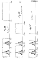
- the solid line curve centred on f shows the combined amplitude-frequency response of the transducers IP and OP of the device of Figure 1, including the fundamental passband which is substantially the desired passband of the electrical filter formed by the device and four side lobes on either side of the fundamental passband extending over a frequency range f + 0.5 f , which is the frequency range outside which side lobes of significant amplitude will not usually be present.
- the solid line curve centred on 3f o shows a substantially repeat amplitude-frequency response of the device including a third harmonic passband at 3f o and side lobes over a frequency range 3f + 0.5 f .
- the dashed line curve shows the wideband amplitude-frequency response of the mulistrip coupler MSA1 over the frequency range 0 to 6f S1 which includes a passband between 0 and 2f S1 , a stopband between 2f S1 and 4f S1 and a further passband between 4f S1 and 6f S1 ; the well known stopband frequency f S1 notch in the multistrip coupler response is also shown.
- the amplitude-frequency response of a multistrip coupler over a range of frequencies 0 to 6f S1 restricted to the special case where the mark-to-space ratio of the strips is substantially one-to-one and showing that in this case the wideband frequency response of a single strip imposes a stopband in the response of the multistrip coupler between 2f S1 and 4f S1 , has not previously been shown.
- the solid line curve in each case shows the combined amplitude-frequency response of the transducers IP and OP of the device of Figure 2 over a frequency range f + 0.5f o
- the dotted line curve in each case shows the response of these transducers over a frequency range 3f o + 0.5f which is within the stopband in the dashed line respone of the multistrip coupler MSA2 and is therefore suppressed in the response of the device including that coupler.
- Figures 3B and 3C show the limits of the range of the centre-to-centre spacing of the strips of the multistrip coupler according to the invention.
- centre-to-centre strip spacing at which f o /f s is substantially 1.0 must be excluded, that is to say that the notch in the multistrip coupler response at the well-known mean stopband frequency f (f S21 in Figure 3B and f S22 in Figure 3C) must be separated from the fundamental passband at the frequency f which is substantially the desired passband of the electrical filter formed by the device.
- the width and spacing of all the strips ST is the same distance d 2 , and furthermore the centre-to-centre spacing of all the strips ST is the same distance ⁇ S2 /2.
- the third harmonic suppression technique according to this invention is used together with this group weighting technique, in which case the shaped fundamental and harmonically repeated passbands of the multistrip coupler will be subject to the stopband in the frequency range 2f s to 4f s .
- the jog geometry multistrip coupler which may also be group-weighted, is the subject of European Patent Application 81200147.7 (Publication number 0034851 A3).
Landscapes
- Physics & Mathematics (AREA)
- Acoustics & Sound (AREA)
- Surface Acoustic Wave Elements And Circuit Networks Thereof (AREA)
Applications Claiming Priority (2)
| Application Number | Priority Date | Filing Date | Title |
|---|---|---|---|
| GB8112452A GB2097212A (en) | 1981-04-22 | 1981-04-22 | Acoustic wave bandpass electrical filters |
| GB8112452 | 1981-04-22 |
Publications (3)
| Publication Number | Publication Date |
|---|---|
| EP0063839A2 true EP0063839A2 (fr) | 1982-11-03 |
| EP0063839A3 EP0063839A3 (en) | 1983-05-11 |
| EP0063839B1 EP0063839B1 (fr) | 1985-01-09 |
Family
ID=10521281
Family Applications (1)
| Application Number | Title | Priority Date | Filing Date |
|---|---|---|---|
| EP82200451A Expired EP0063839B1 (fr) | 1981-04-22 | 1982-04-14 | Filtres éléctriques passe-bande à ondes acoustiques |
Country Status (6)
| Country | Link |
|---|---|
| US (1) | US4427956A (fr) |
| EP (1) | EP0063839B1 (fr) |
| JP (1) | JPS57197909A (fr) |
| CA (1) | CA1184261A (fr) |
| DE (1) | DE3261816D1 (fr) |
| GB (1) | GB2097212A (fr) |
Cited By (1)
| Publication number | Priority date | Publication date | Assignee | Title |
|---|---|---|---|---|
| EP0278765A3 (en) * | 1987-02-13 | 1989-10-11 | Kabushiki Kaisha Toshiba | Surface acoustic wave filter |
Families Citing this family (7)
| Publication number | Priority date | Publication date | Assignee | Title |
|---|---|---|---|---|
| JPS6029611A (ja) * | 1983-07-27 | 1985-02-15 | Sony Magnescale Inc | 検出ヘツド |
| KR860000162B1 (ko) * | 1984-05-14 | 1986-02-27 | 금성계전 주식회사 | 탄성표면파 장치 |
| JPS61251223A (ja) * | 1985-04-27 | 1986-11-08 | Pioneer Electronic Corp | 弾性表面波共振子 |
| US5212420A (en) * | 1991-09-03 | 1993-05-18 | Motorola, Inc. | Method and apparatus for surface acoustic wave reflector grating |
| JPH0685597A (ja) * | 1992-09-02 | 1994-03-25 | Mitsubishi Electric Corp | 弾性表面波装置 |
| US5363073A (en) * | 1992-10-19 | 1994-11-08 | Motorola, Inc. | Saw resonator filter with a multistrip coupler disposed in the resonator gaps |
| DE102007028291B4 (de) * | 2007-06-20 | 2013-04-25 | Epcos Ag | Mit akustischen Oberflächenwellen arbeitendes Transversalfilter |
Family Cites Families (3)
| Publication number | Priority date | Publication date | Assignee | Title |
|---|---|---|---|---|
| GB2070379B (en) | 1980-02-21 | 1984-05-16 | Philips Electronic Associated | Acoustic wave bandpass electrical filters |
| US4336515A (en) | 1980-10-10 | 1982-06-22 | Zenith Radio Corporation | Acoustic filter with harmonic rejection |
| US4370633A (en) | 1981-01-19 | 1983-01-25 | U.S. Philips Corporation | Acoustic wave bandpass electrical filters |
-
1981
- 1981-04-22 GB GB8112452A patent/GB2097212A/en not_active Withdrawn
-
1982
- 1982-03-31 CA CA000400112A patent/CA1184261A/fr not_active Expired
- 1982-04-12 US US06/367,491 patent/US4427956A/en not_active Expired - Fee Related
- 1982-04-14 DE DE8282200451T patent/DE3261816D1/de not_active Expired
- 1982-04-14 EP EP82200451A patent/EP0063839B1/fr not_active Expired
- 1982-04-19 JP JP57064103A patent/JPS57197909A/ja active Granted
Non-Patent Citations (3)
| Title |
|---|
| 1979 ULTRASONICS SYMPOSIUM PROCEEDINGS, 26th-28th September 1979, pages 537-540, Monteleone Hotel, New Orleans, L.A., USA; SUDHAKAR P. et al.: "A superposition model for surface acoustic wave multistrip coupler". * |
| ELECTRONICS LETTERS, vol. 16, no. 10, May 1980, pages 356-358, London, G.B., MURRAY R.J. et al.: "Harmonic suppression in surface-acoustic-wave devices using jogged multistrip couplers". * |
| IEEE TRANSACTIONS ON SONICS AND ULTRASONICS, vol. SU-27, no. 2, March 1980, pages 90-93, New York, USA, SUTHERS M.S. et al.: "SAW bandpass filter design using hermitian function technique". * |
Cited By (1)
| Publication number | Priority date | Publication date | Assignee | Title |
|---|---|---|---|---|
| EP0278765A3 (en) * | 1987-02-13 | 1989-10-11 | Kabushiki Kaisha Toshiba | Surface acoustic wave filter |
Also Published As
| Publication number | Publication date |
|---|---|
| CA1184261A (fr) | 1985-03-19 |
| GB2097212A (en) | 1982-10-27 |
| EP0063839B1 (fr) | 1985-01-09 |
| DE3261816D1 (en) | 1985-02-21 |
| JPS57197909A (en) | 1982-12-04 |
| US4427956A (en) | 1984-01-24 |
| JPH0245848B2 (fr) | 1990-10-12 |
| EP0063839A3 (en) | 1983-05-11 |
Similar Documents
| Publication | Publication Date | Title |
|---|---|---|
| US4353046A (en) | Surface acoustic wave device with reflectors | |
| EP0056690B1 (fr) | Résonateur à ondes acoustiques de surface | |
| US4162465A (en) | Surface acoustic wave device with reflection suppression | |
| EP0184508B1 (fr) | Transducteur à ondes acoustiques de surface | |
| US7023300B2 (en) | Surface wave devices with low passband ripple | |
| US4079342A (en) | Fanned multistrip coupler filters | |
| EP0026114B1 (fr) | Dispositif à ondes acoustiques de surface | |
| US4143340A (en) | Acoustic surface wave device with improved transducer | |
| EP0063839B1 (fr) | Filtres éléctriques passe-bande à ondes acoustiques | |
| EP0840446B1 (fr) | Filtre unidirectionnel à ondes acoustiques de surface | |
| US4370633A (en) | Acoustic wave bandpass electrical filters | |
| US4357584A (en) | Acoustic wave devices | |
| JP4014630B2 (ja) | 弾性表面波装置 | |
| US4513261A (en) | Low-loss acoustic wave filter device | |
| JPH047607B2 (fr) | ||
| US4365220A (en) | Surface wave circuit device | |
| JP3137064B2 (ja) | 弾性表面波フィルタ | |
| US4727275A (en) | Acoustic surface wave device | |
| US4472653A (en) | Electrode pattern for surface acoustic wave device | |
| US4185218A (en) | Piezoelectric acoustic surface wave filter coupler | |
| EP0098116B1 (fr) | Dispositif à ondes acoustiques de surface | |
| US6559739B2 (en) | String weighted surface acoustic wave transducer | |
| JP3329115B2 (ja) | 表面波装置 | |
| EP0034851B1 (fr) | Filtres électriques passe-bande à ondes acoustiques de surface | |
| JPS5997216A (ja) | 弾性表面波フイルタ |
Legal Events
| Date | Code | Title | Description |
|---|---|---|---|
| PUAI | Public reference made under article 153(3) epc to a published international application that has entered the european phase |
Free format text: ORIGINAL CODE: 0009012 |
|
| 17P | Request for examination filed |
Effective date: 19820414 |
|
| AK | Designated contracting states |
Designated state(s): DE FR GB |
|
| PUAL | Search report despatched |
Free format text: ORIGINAL CODE: 0009013 |
|
| AK | Designated contracting states |
Designated state(s): DE FR GB |
|
| GRAA | (expected) grant |
Free format text: ORIGINAL CODE: 0009210 |
|
| AK | Designated contracting states |
Designated state(s): DE FR GB |
|
| REF | Corresponds to: |
Ref document number: 3261816 Country of ref document: DE Date of ref document: 19850221 |
|
| ET | Fr: translation filed | ||
| PLBE | No opposition filed within time limit |
Free format text: ORIGINAL CODE: 0009261 |
|
| STAA | Information on the status of an ep patent application or granted ep patent |
Free format text: STATUS: NO OPPOSITION FILED WITHIN TIME LIMIT |
|
| 26N | No opposition filed | ||
| PGFP | Annual fee paid to national office [announced via postgrant information from national office to epo] |
Ref country code: GB Payment date: 19930401 Year of fee payment: 12 |
|
| PGFP | Annual fee paid to national office [announced via postgrant information from national office to epo] |
Ref country code: FR Payment date: 19930428 Year of fee payment: 12 |
|
| PGFP | Annual fee paid to national office [announced via postgrant information from national office to epo] |
Ref country code: DE Payment date: 19930628 Year of fee payment: 12 |
|
| PG25 | Lapsed in a contracting state [announced via postgrant information from national office to epo] |
Ref country code: GB Effective date: 19940414 |
|
| GBPC | Gb: european patent ceased through non-payment of renewal fee |
Effective date: 19940414 |
|
| PG25 | Lapsed in a contracting state [announced via postgrant information from national office to epo] |
Ref country code: FR Effective date: 19941229 |
|
| PG25 | Lapsed in a contracting state [announced via postgrant information from national office to epo] |
Ref country code: DE Effective date: 19950103 |
|
| REG | Reference to a national code |
Ref country code: FR Ref legal event code: ST |