EP0063877A2 - A pneumatically operated engine for toys - Google Patents
A pneumatically operated engine for toys Download PDFInfo
- Publication number
- EP0063877A2 EP0063877A2 EP82301790A EP82301790A EP0063877A2 EP 0063877 A2 EP0063877 A2 EP 0063877A2 EP 82301790 A EP82301790 A EP 82301790A EP 82301790 A EP82301790 A EP 82301790A EP 0063877 A2 EP0063877 A2 EP 0063877A2
- Authority
- EP
- European Patent Office
- Prior art keywords
- rocker member
- piston
- valve rod
- port
- cylinder
- Prior art date
- Legal status (The legal status is an assumption and is not a legal conclusion. Google has not performed a legal analysis and makes no representation as to the accuracy of the status listed.)
- Granted
Links
Images





Classifications
-
- F—MECHANICAL ENGINEERING; LIGHTING; HEATING; WEAPONS; BLASTING
- F01—MACHINES OR ENGINES IN GENERAL; ENGINE PLANTS IN GENERAL; STEAM ENGINES
- F01B—MACHINES OR ENGINES, IN GENERAL OR OF POSITIVE-DISPLACEMENT TYPE, e.g. STEAM ENGINES
- F01B17/00—Reciprocating-piston machines or engines characterised by use of uniflow principle
- F01B17/02—Engines
-
- A—HUMAN NECESSITIES
- A63—SPORTS; GAMES; AMUSEMENTS
- A63H—TOYS, e.g. TOPS, DOLLS, HOOPS OR BUILDING BLOCKS
- A63H29/00—Drive mechanisms for toys in general
- A63H29/10—Driving mechanisms actuated by flowing media
- A63H29/16—Driving mechanisms actuated by flowing media by steam or compressed air
Definitions
- the present invention relates to a pneumatically operated engine which is powered by the pressure of a compressed gas.
- a pneumatically operated engine for toys powered by a gas of a relatively low pressure has already been proposed by the applicant of the present patent application (Japanese Unexamined Patent Application No. 56-5684).
- This engine comprises a cylinder which is served with a compressed gas such as air compressed to 2 to 3 atmospheres from a source of compressed gas such as air tank, a piston which is actuated in the cylinder by the compressed gas, a piston rod which reciprocally moves together with the piston, a crank which converts the reciprocal motion of the piston rod into rotational motion, a feed valve provided in a feed path which communicates the source of compressed gas with the cylinder, a valve rod which moves in the axial directions to open and close an exhaust path which communicates the cylinder with the open air and to open and close the feed valve, and a valve rod-moving mechanism which is interlocked with the rotation of the crank to move the valve rod in the axial directions.
- the rotary shaft of the crank serves
- the above-mentioned engine has been so constructed that the reciprocal motion of the piston is converted into rotational motion to produce the output.
- This engine therefore cannot be adapted to the toys which are designed to operate relying upon the reciprocal motion of the piston but not relying upon the rotational motion.
- the piston moves from the top dead center to the bottom dead center being pushed by the compressed gas.
- the piston must be raised from the bottom dead center to the top dead center by the inertial force of the revolving output shaft via crank. Accordingly, when the toy is not of the type which is powered by the rotational motion or which does not have a rotary output shaft, the piston is not allowed to reciprocally move continuously.
- a pneumatically operated engine for toys having a cylinder that is served with the compressed air from a source of compressed air, a piston actuated in said cylinder by said compressed air, a piston rod which reciprocally moves together with said piston, a valve rod which moves in the axial directions to open and close a feed port communicating said source of compressed air with said cylinder and to open and close an exhaust port communicating said cylinder with the open air, and a valve rod-moving mechanism which is interlocked with said piston rod to move said valve rod in the axial directions, wherein a return spring is coupled to said piston rod to return the piston to the top dead center after it has been moved from the top dead center to the bottom dead center by the compressed air, said valve rod-moving mechanism has a first rocker member rotatably coupled to said piston rod which protrudes beyond the cylinder, has a second rocker member to which is coupled an end portion of said valve rod that protrudes beyond said exhaust port, such that said valve rod moves between a position at which said feed port
- Figs. 1 and 2 illustrate a pneumatically operated engine for toys according to an embodiment of the present invention.
- the engine consists of a transparent cylinder made of a synthetic resin, a synthetic resin piston 4 which is contained in the cylinder to reciprocally move therein and which has a flexible flange 4a at the upper peripheral edge thereof, a piston rod 6 connected to the piston 4 as a unitary structure, a valve rod 8 for controlling the air fed to, or exhausted from, the cylinder 1, a valve rod-moving mechanism 10 which is interlocked with the piston rod 6 to move the valve rod 8 in the axial directions, and a spring 12 for returning the piston 4 from the bottom dead center to the top dead center.
- the cylinder 2 has an opening.14 at its upper end to feed and exhaust the air, and has an opening 16 at its lower end so that the piston rod 6 can be downwardly protruded.
- a flexible tube 18 is connected to the upper opening 14 for feeding and exhausting the air, and forms a feed/ exhaust path 24 communicated with a feed port 20 and an exhaust port 22 that are opened and closed by the valve rod 8.
- the feed port 20 and exhaust port 22 are defined by a cylindrical path member 26 formed by the side of the cylinder 2, and are opened and closed by the valve rod 8 which is inserted in the path member 26 and which moves in the axial directions.
- valve rod 8 movably penetrates through boundary portions of the feed port 20, exhaust port 22 and feed/exhaust path 24, and is composed of a rod having a diameter suited for closing them.
- Cut-away portions 8a, 8b which stretch in the axial direction are formed at an end portion (top portion in the drawings) and at a middle portion of the valve rod 8.
- the cut-away portion 8a at the upper end is positioned at a boundary between the feed port 20 and the feed/exhaust path 24 as shown in Fig. 1
- the feed port 20 is opened.
- the cut-away portion 8b at the middle portion is positioned at a boundary between the exhaust port 22 and the feed/exhaust path 24 as shown in Fig. 2
- the exhaust port 22 is opened.
- the valve rod-moving mechanism 10 consists of a first rocker member 30 which is swingably connected by a pin 28 to the piston rod 6 that downwardly protrudes from the cylinder 2, a second rocker member 32 to which is rotatably connected the other end (lower portion in the drawings) of the valve rod 8, and a positioning spring 34 which is fitted between the rocker member 30 and the rocker member 32.
- the first rocker member 30 To one end of the first rocker member 30 is hooked one end of the return coil spring 12 of which the other end is fastened to the cylinder 2; i.e., one end of the first rocker member 30 is upwardly pulled by the spring 12.
- the other end of the first rocker member 30 is rotatably coupled by a pin (not shown) to a mounting plate 36 which is formed together with the cylinder 2 and the path member 26 as a unitary structure and which downwardly stretches.
- the second rocker member 32 consists of a nearly heart-shaped member which swings with an inner corner portion of an L-shaped support wall 38 formed on the mounting plate 36 as a fulcrum.
- valve rod 8 is caused to move between the position where the feed port 20 is opened through the cut-away portion 8a (Fig. 1) and the position where the exhaust port 22 is opened through the cut-away portion 8b (Fig. 2).
- a nearly heart-shaped stopper is rotatably provided at a lower portion of the mounting plate 36 to form means for halting the operation of the engine by holding the second rocker member 32 at a position where the exhaust port is opened.
- the positioning spring 34 consists of a leaf spring with its ends being supported by an end portion of the first rocker member 30 and the second rocker member 32.
- the positioning spring 34 sets the second rocker member 32 at a position where the feed port is opened.
- the positioning spring 34 sets the second rocker member 32 at a position where the exhaust port is opened.
- the pneumatically operated engine for toys shown in Figs. 1 and 2 is constructed as mentioned above.
- the compressed air will be supplied to the engine in the following away.
- the stopper 40 is set to the disengaging position as shown in Fig. 1, and the compressed air is fed from the source of compressed air such as a manually operated air pump A shown in Fig. 1 into the inlet of the feed port 20 adjacent to the cylinder 2 through a flexible tube B.
- the compressed air is supplied from the feed port 20 into the cylinder 2 via feed/exhaust path 24, whereby the piston 4 is lowered together with the piston rod 6 overcoming the tensile force of the return coil spring 12.
- the first rocker member 30 of the valve rod-moving mechanism 10 turns clockwise in Fig. 1 with the left end as a center and, hence, the positioning spring 34 is turned in the same direction.
- the second rocker member 32 stays at the position of Fig. 1. Accordingly, the feed port 20 remains open, and the air is supplied into the cylinder 2.
- the stopper 40 should be turned to a position shown in Fig. 2 to hold the second rocker member 32 at the position for opening the exhaust port (for closing the feed port).
- the piston 4 comes into halt at the position of top dead center.
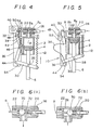
- Figs. 3 and 4 illustrate a second embodiment of the invention.
- the engine of the second embodiment consists of a cylinder 2, a piston 4, a piston rod 6, a valve rod 8, a valve rod-moving mechanism 10 and a return spring 12, and is fundamentally the same as the above-mentioned first embodiment, but is different in regard to the below-mentioned respects.
- the path member 26 defining the feed port 22 and.the exhaust port 22 is mounted on the upper end of the cylinder 2, whereby the feed port 20 and the exhaust port 22 are directly communicated with the feed/exhaust opening 14 of the cylinder 2 without passing through the feed/exhaust path 24 employed in the first embodiment.
- This setup is advantageous with regard to that no flexible tube 18 (Figs. 1 and 2) is necessary to form feed/exhaust path.
- the valve rod-moving mechanism 10 consists of a first rocker member 30 rotatably connected by a pin 28 to the piston rod 6, a second rocker member 32 which is so disposed as to move the valve rod 8 in the axial directions thereof (in the directions perpendicular to the directions in which the piston 4 moves), as well as a positioning spring 34 for connecting these two rocker members together, and a third rocker member 42.
- the first rocker member 30 consists of an L-shaped member with its corner portion rotatably supported by a mounting plate 36 via a pin 44.
- the return spring 12 is connected to an end portion of the first rocker member 30.
- the other end of the first rocker member 30, however, has an elongated hole 46 in which is inserted a pin 47 provided at the lower end of the third rocker member 42, such that the first rocker member 30 and the third rocker member are rotatably coupled together.
- the second rocker member 32 consists of a slender member with its middle portion being coupled to a protruded end of the valve rod 8 and its lower portion being rotatably mounted on the mounting plate 36 by a pin 48.
- the pin 48 also rotatably supports the upper end of the third rocker member 42. Therefore, the third rocker member 42 which is coupled to the first rocker member 30 oscillates with the pin 48 as a center.
- the positioning spring 34 consists of a coil spring of which the one end is hooked to a projection 50 at the upper end of the second rocker member 32 and of which the other end is hooked to a pin 47 of the third rocker member 42.
- the coil spring 34 turns via the third rocker member 42, whereby the second rocker member 32 is turned with the pin 48 as a center.
- a stopper protrusion 52 is provided at the upper end of the mounting plate 36 to prevent the second rocker member 32 from being rotated in the clockwise direction in excess of the position for closing the feed port (position for opening the exhaust port), in addition to the stopper 40 which holds the second rocker member 32 at the position for closing the feed port to halt the operation of the engine.
- a semicircular stopper protrusion 54 is provided at the lower end of the mounting plate 36 to stop the first rocker member 30 rotating in the clockwise direction at the position of bottom dead center of the piston 4. Provision of the stopper protrusion 54 eliminates the need for forming a flange at the lower end of the cylinder to prevent the escape of piston, that is done in the first embodiment. That is, the opening at the lower end of the cylinder 2 needs be formed in the same diameter as the inner diameter of the cylinder. In effect, the engine can be assembled easily.
- the operation of the second embodiment is the same as that of the first embodiment. That is, if the compressed air is fed into the inlet of the feed port 20 from the source of compressed gas such as from the air tank C storing the compressed air via a flexible tube D under the condition in which the engine is at rest as shown in Fig. 3, the piston is downwardly moved to assume the state shown in Fig. 4. The piston 4 then returns to the state of Fig. 3 owing to the function of the return spring 12. The reciprocal operation of the piston is continued as far as the compressed air is supplied from the air tank C.
- the compressed air should be stored in the tank C using an air pump A which is shown in Fig. 1.
- the air tank C has a feed valve 56 which is communicated with the interior of the air tank C and with the flexible tube D for feeding the air.
- the feed valve 56 is slidably contained in a tubular portion 58 that outwardly protrudes on the tank C.
- the tubular portion 58 has a small diameter on the side of the inlet port so that it is closed by the feed valve 56, and has a cut-away portion 60 in a stepped portion 59 of the inner wall on the side of the tank.
- the feed valve 56 moves toward the right in the drawing to come into contact with the stepped portion 59 on the side of the tank; the compressed air is allowed to enter into the tank C through the cut-away portion 60.
- Supply of the compressed air should be discontinued when a desired amount of compressed air is stored in the tank. Due to the pneumatic pressure in the tank, the feed valve 56 is pressed onto the inlet side of the tubular portion 58 to close the inlet port; therefore, the compressed air is stored in the tank C.
- the air tank C is provided with a safety valve 62.
- the safety valve 62 consists of a circular protuberance 64 formed by stretching a portion of the outer wall of the tank C, and a circular rubber cap 66 fitted onto the protuberance 64. The upper end of the cap 66 comes into contact with a cylindrical protrusion of the tank C to close it, and further has a through hole 68 in a peripheral portion of the cylindrical protrusion.
- the pressure in the tank increases and exceeds a predetermined value (determined by the material of the cap 66)
- a predetermined value determined by the material of the cap 66
- the upper end of the cap 66 separates away from the cylindrical protrusion of the tank, whereby the compressed air in the tank flows through the gap and escapes into the open air through the hole 68 of the cap 66. Therefore, the pressure in the tank decreases until the rubber cap 66 closes again the cylindrical protrusion; the pressure in the tank is maintained at a stable level.
- Fig. 5 illustrates a third embodiment of the invention.
- the engine of this embodiment is fundamentally constructed in the same manner as the engines of the above-mentioned two embodiments.
- the engine of this embodiment is different from the above embodiments with regard to that both ends of a positioning spring 34 consisting of a nearly C-shaped leaf spring is coupled to the upper end of the L-shaped first rocker member 30 that is rotatably attached at its corner portion to the mounting plate 36 by a pin 44, and to the lower end of the second rocker member 32 that is rotatably attached at its middle portion by a pin 48 to the mounting plate 36, thereby to constitute the valve rod-moving mechanism 10.
- the upper end of the spring 34 is fastened to the lower end of the second rocker member 32, and the lower end of the spring 34 is fitted to a V-shaped groove formed in the upper end of the first rocker member 30 so as to move with its lower end as a fulcrum. Further, a stopper protrusion 52 is provided beneath the stopper 40 to restrict the turn of the second rocker member 32 in the clockwise direction.
- the engine therefore, assumes the exhaust condition, and where the piston 4 and piston rod 6 are raised by the tensile force of the return spring 12, and the first rocker member 30 rotates in the counterclockwise direction.
- the piston 4 reaches the position of top dead center, the second rocker member 32 rotates in the counterclockwise direction by the function of the spring 34 and returns to the condition shown in Fig. 5.
- the piston 4 performs the reciprocal motion as far as the air is fed, like the above-mentioned two embodiments.
- valve rod 8 for controlling the feed and exhaust of the air into or out of the cylinder needs not be limited to the above-mentioned rod having two cut-away portions 8a, 8b, but may simply be a rod having a predetermined length.
- FIG. 6 illustrates a concrete setup in which a ball valve 70 is accommodated in an air path formed between the outlet of the feed port 20 and the inlet of the exhaust port 22, and the ball valve 70 is always pressed onto the side of the exhaust port by a coil spring 72 interposed on the side of the feed port thereby to close the inlet, and in which the inner diameter of the inlet of the exhaust port is made to be larger than the diameter of the valve rod 8. Therefore, when the valve rod 8 is located at a retracted position as shown in Fig. 6(a) (which corresponds to the position for opening the feed valve shown in Figs. 1, 3 and 5), the exhaust port 22 is, closed, and the feed port 20 is opened.
- Fig. 6 The construction shown in Fig. 6 is advantageous with regard to two respects. First, as compared with the construction consisting of valve rod alone of Figs. 1 to 5, the valve rod 8 of Fig. 6 needs not have cut-away portions 8a and 8b. Second, the valve rod 8 moves without in contact with the peripheral walls that define the outlet of the feed port 20 and the inlet of the exhaust port 20, and no particular durability is required for the peripheral walls.
- Fig. 7 illustrates a running toy 100 which runs being powered by the engine of Fig. 5.
- the running toy has pairs of front and rear wheels 104, 106 that are coupled by an expansion mechanism 101 which is constructed by connecting a plurality of coupling members 102, and has axles 105 (see Fig. 8(c)) for front and rear wheels that penetrate through bearing members 108 located at the front and rear positions of the expansion mechanism 101.
- the bearing members 108 rotatably support one of the two coupling members 102 at the front and rear ends of the expansion mechanism 101 by means of a pin 110, and slidably support another coupling member 102 by means of a pin 114 which is inserted in an elongated hole 112 that is formed in the bearing members 108 in parallel with the axles. Further, a projection 116 is formed at an end portion on one side of the bearing members 108 (right side when faced forward in the drawing), such that the front wheels 104 and the rear wheels 106 are allowed to rotate only in the forward direction as indicated by arrow in Fig. 8, i.e., in order to prevent the wheels from being rotated backwards.
- a ratchet portion 118 On the inner side of the wheels 104R, 106R of the right side, there is formed a ratchet portion 118 as shown in Fig. 8(c). Moreover, a through hole 119 is formed in the extreme right end of the bearing members 108 in an elongated manner in the back and forth directions, such that the ratchet portion 118 of the wheels is allowed to slightly move in the back and forth directions depending upon the running direction.
- the running toy 100 of Fig. 7 is equipped with the engine of Fig. 5 as a source for running by expansion and contraction. That is, the running toy consists of a pin 120 studded at a central portion of the coupling member 102 located at the center of the expansion mechanism 101 (Figs. 8(a) and (b)), a circular frame 122 mounting the engine of Fig. 5, the circular frame 122 being supported by the pin 120, a short coupling member 103 (Figs.
- the expansion mechanism 101 is expanded and contracted by turning the coupling member 130 in the back and forth directions with its base end as a center.
- a drive rod 132 which stretches from the central portion of the coupling member 130 in the back and forth directions, is rotatably coupled, and the front end of the drive rod 132 is rotatably coupled to a transmission member 136 which swings with a support shaft 134 as a center.
- the transmission member 136 has a coupling arm 136a which downwardly stretches and which is coupled to the drive rod 132, and a coupling arm 136b which forwardly stretches defining a predetermined angle relative to the coupling arm 136a.
- the coupling arm 136b has been rotatably coupled to the lower end of the piston rod 6 of the engine shown in Fig. 5. Therefore, when the engine is operated and the piston rod 6 performs the reciprocal motion, the drive rod 132 is moved in the back and forth directions via the transmission member 136, and the expansion mechanism 101 is expanded and contracted via the coupling member 130.
- the running toy 100 is further equipped with the air tank C having safety valve which is shown in Fig. 3 as a source for supplying the compressed air into the engine.
- the air tank C is installed on the circular frame 122.
- the stopper 40 for halting the operation of the engine is set to the position for halting the operation by turning a knob 138 that is provided in concentric with the stopper 40, and the pump A shown in Fig. 1 is manually operated to store a suitable amount of compressed air in the air tank C. Thereafter, the knob 138 is turned to liberate the stopper 40 from the stop position.
- the piston 4 and piston rod 6 then reciprocally move as mentioned earlier, and the expansion mechanism 101 undergoes the expansion and contraction as shown in Figs. 8(a) and (b).
- the running toy 100 goes ahead owing to the functions of the front wheels 104 that turn when the expansion mechanism 101 expands and the rear wheels 106 that turn when the expansion mechanism 101 contracts. This operation continues until the stopper 40 is set to the stop position or until the compressed air in the air tank C is all consumed.
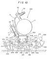
- Figs. 9 and 10 illustrate a running toy 200 which runs being carried on four legs 202 on the right side and four legs 202 on the left side, i.e., being carried on a total of eight legs 202, and being powered by the pneumatically operated engine of the present invention, as a second example of using the engine.
- the running toy 200 has the legs 202 that are swingably attached to the lower portions of a base frame (chassis) 204 on which are mounted the engine and the air tank C with safety valve that are shown in Figs. 3 and 4.
- the legs 202 are attached as mentioned below.
- each swinging leg 202 consists of a fan-shaped member having an opening 206 on one side and a weight 208 on the other side.
- the central portions of the fan-shaped members are rotatably supported, via four support axles 214 that stretch in the right and left directions, by the ends of support members 212 which are rotatably supported at their middle portions by four leg portions 210 that downwardly stretch from the base frame 204 at the front and rear portions on both the right and left sides, in such a manner that the opening 206 of each of the legs is located in front.
- the rear portion of the legs 202 is located lower than the front portion since the center of gravity is located in the rear portion.
- the arcuate periphery of the swinging legs 202 is so shaped that the radius of curvature as measured from the support axle 214 gradually increases from the front end of the opening 206 toward the rear end where the weight 208 is located. Consequently, when the rear end is grounded as shown in Fig. 10, the swinging legs 202 rotate toward the front end and come into halt in the state in which the front end is grounded.
- two support axles 214 located on the front side of the support members 212 have a coupling portion 212 that downwardly stretch from the middle portion thereof.
- the lower end 216 of each of the coupling portions 216 are rotatably linked together through a coupling rod 218.
- the lower end of the piston rod 6 of the engine is rotatably linked to a middle portion of the second support axle 214 from the front, i.e., rotatably linked to a middle portion of the support axle 214 located at the rear end of the two front support members 212.
- the second support axle 214 When the piston 4 is located at the top dead center, the second support axle 214 is lifted up, whereby the pair of right and left swinging arms 202 at the front end are lowered via the two front support members 212 that are tilted, and the pair of right and left swinging legs 202 at the rear end are raised. Furthermore, due to the coupling rod 218 connecting the first support axle 214 to the third support axle 214, the two rear support members 212 are also tilted, so that the pair of right and left swinging legs 202 at the front end are lowered, and the pair of right and left swinging legs 202 at the rear end are raised. If the running toy under this state is placed on the ground or the like, rear portions of the first and third four swinging legs 202 on the right and left sides are grounded. As the swinging legs 202 rotate forward, the running toy 200 goes ahead by a distance corresponding to the rotating angle of the swinging legs.
- the second support axle 214 is located lower than the first support axle 214. Therefore, the first pair of right and left swinging legs 202 are located high, and the second pair of right and left swinging legs 202 are located low. Due to the coupling rod 218, furthermore, the third pair of right and left swinging legs 202 are located high, and the fourth pair of right and left swinging legs 202 are located low. In this case, the second and fourth four swinging legs 202 on the right and left sides are brought into contact with the ground and are turned. Therefore, the running toy 200 goes ahead by a distance corresponding to the rotating angle of the swinging legs.
- the running toy 200 is constructed as mentioned above. Therefore, if the engine is energized by the compressed air stored in the air tank C. the first and third four swinging legs 202 and the second and fourth four swinging legs 202 are grounded alternatingly owing to the reciprocating motion of the piston 4 and piston rod 6, and the grounded swinging legs 202 rotate as mentioned above. Therefore, the running toy 200 advances in a continuous manner.
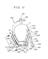
- Figs. 11 and 12 illustrate a jumping toy 300 which performs the jumping continuously being powered by the engine of the invention, as a third example of using the engine.
- the jumping toy 300 has a pair of front legs 304 and a pair of rear legs 306 that are attached to a nearly square base frame 302 on which are mounted the pneumatically operated engine and the air tank C with safety valve, and further has a rotatably mounted control lever 308 for bringing the feed of air or exhaust of air of the engine into complete synchronism with the jumping operation.
- the pair of right and left front legs 304 of the jumping toy are supported at their rear positions by the ends of a support axle 310 that rotatably penetrates through the right and left side portions of the base frame 302, and are rotatably linked at their rear ends to the base portions of the rear legs 306 by pins 312.
- the pair of right and left rear legs 306 consist of first leg members 314 which are coupled at their ends to the front legs 304 by the pins 312 on the right and left sides of the base frame 302, second leg members 318 supported at their ends by the end portions of a rear support axle 316 that penetrate through the right and left side portions of the base frame 302 in parallel with the support axle 310 of the front legs 304, third leg members 324 which are rotatably coupled at their upper ends to the other ends of the first leg members 304 by the pins 320 and which are further rotatably coupled to the other ends of the second leg members 318 by pins 322 at a position adjacent to the position of pins 320, an upper support axle 326 of which the ends are coupled to the first leg members 314 on the right and left sides at a position that forms a parallelogram together with the rear support axle 316 and two pins 322, 320, and fourth leg members 328 of which the ends are rotatably coupled to the upper support axle 326 and to the lower support
- Rollers 330 are rotatably attached by pins 332 to the lower ends of the pair of right and left third leg members 324 that are positioned at the rear end of the jumping toy 300.
- the rollers 330 have been urged to the third leg members 324 by a spring (not shown) so that they will turn only when a rotational force is applied, that is greater than a predetermined value which will be mentioned later.
- the front legs 304 and the rear legs 306 of the jumping toy 300 are constructed as mentioned above.
- Fig. 11 if now the front legs 304 are rotated in the counterclockwise direction with the support axle 310 as a center, the rear legs 306 rotate in the clockwise direction with the support axle 316 as a center, whereby the third leg members 324 kick the ground to perform the jumping (Fig. 12).
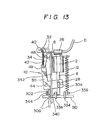
- the jumping toy 300 employs a pneumatically operated engine shown in Fig. 13 as a source for driving the front legs 304 and the rear legs 306.
- This engine is constructed nearly in the same manner as the engines illustrated in conjunction with Figs. 3 and 4, but is different in regard to the below-mentioned points.
- the lower end of the return spring 12 is not coupled to an end of the first rocker member 30, but is coupled via a pin 336 to a coupling portion 334 which stretches forward from the support axle 310 of the front legs 304 nearly in parallel with the front legs 304.
- the first rocker member 30 which is rotatably coupled to the piston rod 6 has an elongated hole 30a into which will be loosely fitted a pin 28 that is studded at a middle portion of the piston rod 6, such that the pin 28 is located at the upper end of the elongated hole 30a when the piston 4 is at the top dead center. This is because, the first rocker member 30 is turned.in the counterclockwise direction in the drawing via pin 28 when the piston 4 and piston rod 6 are raised to the top dead center. The reason for forming the elongated hole 30a will be mentioned later.
- the second rocker member 32 is moved not only by the positioning spring 34 but also by a positioning rod 342 which is interlocked with the control lever 308.
- the control lever 308 is rotatably coupled at its end to the base frame 302 via a pin 344, and has a downwardly folded end portion that is folded nearly at right angles.
- the positioning rod 342 is coupled between the middle portion of the control lever 308 and the end of the nearly L-shaped second rocker member 32 which has the positioning spring 34 hooked at the other end.
- the positioning rod 342 moves up and down thereby to bring the second rocker member 32 to either the position for opening the feed port indicated by a solid line in Fig. 13 or the position for opening the exhaust port indicated by a dot-dash line.
- the jumping toy 300 is constructed as mentioned above.
- the stopper 40 for stopping the engine is set at the stop position (position for closing the feed port)
- a required amount of the compressed air is stored in the air tank C
- the jumping toy 300 placed on the ground moves in the following way. That is, the front legs 304 turn counterclockwisely with the support axle 310 as a center since the piston rod 6 is pushed down from the state of Fig. 11, and the rear legs 306 turn clockwisely with the support axle 316 as a center, such that the toy jumps forward kicking off the ground.
- the support axle 310 is turned by the tensile force of the return spring 12 toward the direction opposite to the direction of feeding the air, whereby the front legs 304 are turned clockwise in Fig. 12 and the rear legs 306 are turned counterclockwise.
- the pin 28 reaches the upper end of the elongated hole 30a, and the first rocker member 30 starts to rotate in the counterclockwise direction in Fig. 13.
- the first rocker member 30 returns to the initial position.
- the second rocker member 32 does not return to the position of solid line in Fig. 13.
- the first rocker member 30 has the elongated hole 30a with which the pin 28 of the piston rod 6 is engaged and, hence, even when the piston reaches the top dead center, the first rocker member 30 does not reach the position at which the second rocker member 32 can be turned via the positioning spring 34.
- the jumping toy 300 repeats the above-mentioned motion to go ahead while jumping.
- the jumping toy jumps and goes ahead at a constant rate even when the ground has different surface conditions. That is, the jumping toy 300 jumps forward as the tips of the front legs 304 and the tips of the rear legs 306 kick off the surface of the ground. In this case, however, the tips of the rear legs 306 must not slip on the ground.
- an anti-slipping means such as rubber plate to the lower ends of the third leg members 324 of the rear legs 306.
- the anti-slipping means may exhibit a large frictional force relative to the surface of the ground, such that the jumping toy having the center of gravity at a high position may fall rearwardly.
- rollers 330 equipped with rubber tires are attached to the lower ends of the third leg member 324, and are pressed onto the third leg members 324 by, for example, a coil spring wound around a pin 332, such that the rollers 330 will turn when the frictional force between the rollers 330 and the ground exceeded a predetermined value.
- the pneumatically operated engine of the invention was illustrated in detail in the foregoing by way of embodiments and examples of using it. If mentioned briefly, the engine of the present invention continuously produces the reciprocal motion that could not be obtained by the conventional engine which produces the revolving output. Accordingly, the engine of the invention can be extensively used for a variety of toys that give different mode of amusement from those of the conventional running toys that are based upon the revolving power.
Landscapes
- Engineering & Computer Science (AREA)
- Mechanical Engineering (AREA)
- General Engineering & Computer Science (AREA)
- Toys (AREA)
Abstract
Description
- The present invention relates to a pneumatically operated engine which is powered by the pressure of a compressed gas.
- A pneumatically operated engine for toys powered by a gas of a relatively low pressure (compressed air of 2 to 3 atmospheres) has already been proposed by the applicant of the present patent application (Japanese Unexamined Patent Application No. 56-5684). This engine comprises a cylinder which is served with a compressed gas such as air compressed to 2 to 3 atmospheres from a source of compressed gas such as air tank, a piston which is actuated in the cylinder by the compressed gas, a piston rod which reciprocally moves together with the piston, a crank which converts the reciprocal motion of the piston rod into rotational motion, a feed valve provided in a feed path which communicates the source of compressed gas with the cylinder, a valve rod which moves in the axial directions to open and close an exhaust path which communicates the cylinder with the open air and to open and close the feed valve, and a valve rod-moving mechanism which is interlocked with the rotation of the crank to move the valve rod in the axial directions. According to the above-mentioned engine, the rotary shaft of the crank serves as an output shaft to drive wheels of model automobiles or the like.
- Like the customary internal combustion engines or similar engines, however, the above-mentioned engine has been so constructed that the reciprocal motion of the piston is converted into rotational motion to produce the output. This engine therefore cannot be adapted to the toys which are designed to operate relying upon the reciprocal motion of the piston but not relying upon the rotational motion. This is because, with the known pneumatically operated engine, the piston moves from the top dead center to the bottom dead center being pushed by the compressed gas. The piston, however, must be raised from the bottom dead center to the top dead center by the inertial force of the revolving output shaft via crank. Accordingly, when the toy is not of the type which is powered by the rotational motion or which does not have a rotary output shaft, the piston is not allowed to reciprocally move continuously.
- Therefore, it is a general object of the present invention to provide a pneumatically operated engine which is suited for the toys that are driven relying upon the reciprocal motion, while making use of advantages of the conventional pneumatically operated engine.
- According to the present invention, there is provided a pneumatically operated engine for toys having a cylinder that is served with the compressed air from a source of compressed air, a piston actuated in said cylinder by said compressed air, a piston rod which reciprocally moves together with said piston, a valve rod which moves in the axial directions to open and close a feed port communicating said source of compressed air with said cylinder and to open and close an exhaust port communicating said cylinder with the open air, and a valve rod-moving mechanism which is interlocked with said piston rod to move said valve rod in the axial directions, wherein a return spring is coupled to said piston rod to return the piston to the top dead center after it has been moved from the top dead center to the bottom dead center by the compressed air, said valve rod-moving mechanism has a first rocker member rotatably coupled to said piston rod which protrudes beyond the cylinder, has a second rocker member to which is coupled an end portion of said valve rod that protrudes beyond said exhaust port, such that said valve rod moves between a position at which said feed port is opened and a position at which said exhaust port is opened, and has a positioning spring which is coupled between said first rocker member and said second rocker member so that said second rocker member moves being interlocked with said first rocker member, and wherein when said piston is located at the top dead center, said valve rod is located and is maintained at a position for opening said feed port and when said piston is located at the bottom dead center, said valve rod is located and is maintained at a position for opening said exhaust port.
- One way of carrying out the invention is described in detail below with reference to drawings which illustrate preferred embodiments, in which:-
- Figs. 1 to 5 are partial section views illustrating the construction and operation of the pneumatically operated engines according to embodiments of the present invention;
- Fig. 6 is a section view showing a mechanism for controlling the feed of air and exhaust of air for the pneumatically operated engine according to a modified embodiment of the present invention;
- Figs. 7 and 8 are perspective views showing the construction of a running toy equipped with an expansion mechanism, as a first example of using the engine of the present invention;
- Fig. 9 is a perspective view showing the construction of a running toy having a plurality of swinging legs, as a second example of using the engine of the present invention;
- Fig. 10 is a section view along the line X-X of Fig. 9;
- Figs. 11 and 12 are side views illustrating the construction and operation of a jumping toy, as a third example of using the engine of the present invention; and
- Fig. 13 is a front view along the line XIII - XIII of Fig. 11, and illustrates a pneumatically operated engine that is used for the jumping toy.
- Figs. 1 and 2 illustrate a pneumatically operated engine for toys according to an embodiment of the present invention. The engine consists of a transparent cylinder made of a synthetic resin, a
synthetic resin piston 4 which is contained in the cylinder to reciprocally move therein and which has aflexible flange 4a at the upper peripheral edge thereof, apiston rod 6 connected to thepiston 4 as a unitary structure, avalve rod 8 for controlling the air fed to, or exhausted from, the cylinder 1, a valve rod-movingmechanism 10 which is interlocked with thepiston rod 6 to move thevalve rod 8 in the axial directions, and aspring 12 for returning thepiston 4 from the bottom dead center to the top dead center. - The
cylinder 2 has an opening.14 at its upper end to feed and exhaust the air, and has an opening 16 at its lower end so that thepiston rod 6 can be downwardly protruded. Aflexible tube 18 is connected to theupper opening 14 for feeding and exhausting the air, and forms a feed/exhaust path 24 communicated with afeed port 20 and anexhaust port 22 that are opened and closed by thevalve rod 8. According to this embodiment, thefeed port 20 andexhaust port 22 are defined by acylindrical path member 26 formed by the side of thecylinder 2, and are opened and closed by thevalve rod 8 which is inserted in thepath member 26 and which moves in the axial directions. If mentioned in further detail, thevalve rod 8 movably penetrates through boundary portions of thefeed port 20,exhaust port 22 and feed/exhaust path 24, and is composed of a rod having a diameter suited for closing them. Cut-away portions 8a, 8b which stretch in the axial direction are formed at an end portion (top portion in the drawings) and at a middle portion of thevalve rod 8. When the cut-away portion 8a at the upper end is positioned at a boundary between thefeed port 20 and the feed/exhaust path 24 as shown in Fig. 1, thefeed port 20 is opened. When the cut-away portion 8b at the middle portion is positioned at a boundary between theexhaust port 22 and the feed/exhaust path 24 as shown in Fig. 2, theexhaust port 22 is opened. - The valve rod-moving
mechanism 10, according to this embodiment, consists of afirst rocker member 30 which is swingably connected by apin 28 to thepiston rod 6 that downwardly protrudes from thecylinder 2, asecond rocker member 32 to which is rotatably connected the other end (lower portion in the drawings) of thevalve rod 8, and apositioning spring 34 which is fitted between therocker member 30 and therocker member 32. - To one end of the
first rocker member 30 is hooked one end of thereturn coil spring 12 of which the other end is fastened to thecylinder 2; i.e., one end of thefirst rocker member 30 is upwardly pulled by thespring 12. The other end of thefirst rocker member 30 is rotatably coupled by a pin (not shown) to amounting plate 36 which is formed together with thecylinder 2 and thepath member 26 as a unitary structure and which downwardly stretches. Thesecond rocker member 32 consists of a nearly heart-shaped member which swings with an inner corner portion of an L-shaped support wall 38 formed on themounting plate 36 as a fulcrum. As thesecond rocker member 32 swings in the upper and lower directions in the drawings, thevalve rod 8 is caused to move between the position where thefeed port 20 is opened through the cut-away portion 8a (Fig. 1) and the position where theexhaust port 22 is opened through the cut-away portion 8b (Fig. 2). In Fig. 2, furthermore, a nearly heart-shaped stopper is rotatably provided at a lower portion of themounting plate 36 to form means for halting the operation of the engine by holding thesecond rocker member 32 at a position where the exhaust port is opened. - The positioning
spring 34 according to this embodiment consists of a leaf spring with its ends being supported by an end portion of thefirst rocker member 30 and thesecond rocker member 32. When thefirst rocker member 30 is located at the upper limit position (corresponds to the top dead center of the piston 4) as shown in Fig. 1, thepositioning spring 34 sets thesecond rocker member 32 at a position where the feed port is opened. When thefirst rocker member 30 is located at the lower limit position (corresponds to the bottom dead center of the piston 4) as shown in Fig. 2, thepositioning spring 34 sets thesecond rocker member 32 at a position where the exhaust port is opened. - The pneumatically operated engine for toys shown in Figs. 1 and 2 is constructed as mentioned above. The compressed air will be supplied to the engine in the following away.
- When the compressed air is not to be supplied into the
cylinder 2, thepiston 4 is held at the top dead center being pulled by thereturn spring 12, and the cut-away portion 8a at the top of thevalve rod 8 permits thefeed port 20 to open. Under this condition, thestopper 40 is set to the disengaging position as shown in Fig. 1, and the compressed air is fed from the source of compressed air such as a manually operated air pump A shown in Fig. 1 into the inlet of thefeed port 20 adjacent to thecylinder 2 through a flexible tube B. The compressed air is supplied from thefeed port 20 into thecylinder 2 via feed/exhaust path 24, whereby thepiston 4 is lowered together with thepiston rod 6 overcoming the tensile force of thereturn coil spring 12. In this case, thefirst rocker member 30 of the valve rod-movingmechanism 10 turns clockwise in Fig. 1 with the left end as a center and, hence, thepositioning spring 34 is turned in the same direction. Thesecond rocker member 32, however, stays at the position of Fig. 1. Accordingly, thefeed port 20 remains open, and the air is supplied into thecylinder 2. - When the
piston 4 reaches the bottom dead center shown in Fig. 2, thesecond rocker member 32 is turned counterclockwisely from the position of Fig. 1 to the position of Fig. 2 due to the resilient force of thepositioning spring 34, whereby thevalve rod 8 is raised to close thefeed port 20, and theexhaust port 22 is opened by the cut-away portion 8b formed at the middle portion of thevalve rod 8. Since no air is fed from the source A of compressed air into thecylinder 2 and-no pressure is exerted on thepiston 4, the tensile force of thereturn spring 12 raises thepiston 4 via thefirst rocker member 30 and thepiston rod 6. In this case, the air in thecylinder 2 above thepiston 4 is exhausted into the open air from the feed/exhaust opening 14 via feed/exhaust path 24 andexhaust port 22. While thepiston 4 is rising, thesecond rocker member 32 is held at the position of Fig. 2; theexhaust port 22 remains opened, and the air is exhausted. - As the
piston 4 returns to the position of top dead center (Fig. 1), thesecond rocker member 32 returns from the position of Fig. 2 to the position of Fig. 1 due to the resilient force of thepositioning spring 34, and thevalve rod 8 is lowered to the initial position for opening the feed port. Therefore, the compressed air is fed again into thecylinder 2 to lower thepiston 4. Thepiston 4 therefore repeats the lowering stroke and the rising stroke to perform the reciprocal motion as far as the air is continuously supplied from the source A of compressed air. When it is desired to stop the operation of the engine, i.e., to stop the reciprocal motion of thepiston 4, the supply of the compressed air should be stopped. However, when the source of compressed air is of the type which continuously supplies the air for a predetermined period of time, such as an air tank, thestopper 40 should be turned to a position shown in Fig. 2 to hold thesecond rocker member 32 at the position for opening the exhaust port (for closing the feed port). Thepiston 4 comes into halt at the position of top dead center. - Figs. 3 and 4 illustrate a second embodiment of the invention. The engine of the second embodiment consists of a
cylinder 2, apiston 4, apiston rod 6, avalve rod 8, a valve rod-movingmechanism 10 and areturn spring 12, and is fundamentally the same as the above-mentioned first embodiment, but is different in regard to the below-mentioned respects. - First, in the second embodiment, the
path member 26 defining thefeed port 22 and.theexhaust port 22 is mounted on the upper end of thecylinder 2, whereby thefeed port 20 and theexhaust port 22 are directly communicated with the feed/exhaust opening 14 of thecylinder 2 without passing through the feed/exhaust path 24 employed in the first embodiment. This setup is advantageous with regard to that no flexible tube 18 (Figs. 1 and 2) is necessary to form feed/exhaust path. - Next, the valve rod-moving
mechanism 10 consists of afirst rocker member 30 rotatably connected by apin 28 to thepiston rod 6, asecond rocker member 32 which is so disposed as to move thevalve rod 8 in the axial directions thereof (in the directions perpendicular to the directions in which thepiston 4 moves), as well as a positioningspring 34 for connecting these two rocker members together, and athird rocker member 42. Thefirst rocker member 30 consists of an L-shaped member with its corner portion rotatably supported by amounting plate 36 via apin 44. Like the first embodiment, thereturn spring 12 is connected to an end portion of thefirst rocker member 30. The other end of thefirst rocker member 30, however, has anelongated hole 46 in which is inserted apin 47 provided at the lower end of thethird rocker member 42, such that thefirst rocker member 30 and the third rocker member are rotatably coupled together. - The
second rocker member 32 consists of a slender member with its middle portion being coupled to a protruded end of thevalve rod 8 and its lower portion being rotatably mounted on themounting plate 36 by apin 48. Thepin 48 also rotatably supports the upper end of thethird rocker member 42. Therefore, thethird rocker member 42 which is coupled to thefirst rocker member 30 oscillates with thepin 48 as a center. - The
positioning spring 34 consists of a coil spring of which the one end is hooked to aprojection 50 at the upper end of thesecond rocker member 32 and of which the other end is hooked to apin 47 of thethird rocker member 42. When thefirst rocker member 30 is turned, thecoil spring 34 turns via thethird rocker member 42, whereby thesecond rocker member 32 is turned with thepin 48 as a center. - In the embodiment as shown in Fig. 4, a
stopper protrusion 52 is provided at the upper end of the mountingplate 36 to prevent thesecond rocker member 32 from being rotated in the clockwise direction in excess of the position for closing the feed port (position for opening the exhaust port), in addition to thestopper 40 which holds thesecond rocker member 32 at the position for closing the feed port to halt the operation of the engine. Further, asemicircular stopper protrusion 54 is provided at the lower end of the mountingplate 36 to stop thefirst rocker member 30 rotating in the clockwise direction at the position of bottom dead center of thepiston 4. Provision of thestopper protrusion 54 eliminates the need for forming a flange at the lower end of the cylinder to prevent the escape of piston, that is done in the first embodiment. That is, the opening at the lower end of thecylinder 2 needs be formed in the same diameter as the inner diameter of the cylinder. In effect, the engine can be assembled easily. - The operation of the second embodiment is the same as that of the first embodiment. That is, if the compressed air is fed into the inlet of the
feed port 20 from the source of compressed gas such as from the air tank C storing the compressed air via a flexible tube D under the condition in which the engine is at rest as shown in Fig. 3, the piston is downwardly moved to assume the state shown in Fig. 4. Thepiston 4 then returns to the state of Fig. 3 owing to the function of thereturn spring 12. The reciprocal operation of the piston is continued as far as the compressed air is supplied from the air tank C. - When there is no compressed air in the air tank C, i.e., when the pressure in the tank is decreased to become equal to the atmospheric pressure, the compressed air should be stored in the tank C using an air pump A which is shown in Fig. 1. For this purpose, the air tank C has a
feed valve 56 which is communicated with the interior of the air tank C and with the flexible tube D for feeding the air. Thefeed valve 56 is slidably contained in atubular portion 58 that outwardly protrudes on the tank C. Thetubular portion 58 has a small diameter on the side of the inlet port so that it is closed by thefeed valve 56, and has a cut-awayportion 60 in a steppedportion 59 of the inner wall on the side of the tank. Therefore, when the compressed air is fed to the inlet port of thetubular portion 58 from the air pump or the like, thefeed valve 56 moves toward the right in the drawing to come into contact with the steppedportion 59 on the side of the tank; the compressed air is allowed to enter into the tank C through the cut-awayportion 60. Supply of the compressed air should be discontinued when a desired amount of compressed air is stored in the tank. Due to the pneumatic pressure in the tank, thefeed valve 56 is pressed onto the inlet side of thetubular portion 58 to close the inlet port; therefore, the compressed air is stored in the tank C. - Thus, a desired amount of compressed air can be stored in the air tank C. When the pressure is excessively increased, however, the tank may undergo the explosion. To prevent the explosion, therefore, the air tank C is provided with a
safety valve 62. Thesafety valve 62 consists of acircular protuberance 64 formed by stretching a portion of the outer wall of the tank C, and acircular rubber cap 66 fitted onto theprotuberance 64. The upper end of thecap 66 comes into contact with a cylindrical protrusion of the tank C to close it, and further has a throughhole 68 in a peripheral portion of the cylindrical protrusion. Therefore, as the pressure in the tank increases and exceeds a predetermined value (determined by the material of the cap 66), the upper end of thecap 66 separates away from the cylindrical protrusion of the tank, whereby the compressed air in the tank flows through the gap and escapes into the open air through thehole 68 of thecap 66. Therefore, the pressure in the tank decreases until therubber cap 66 closes again the cylindrical protrusion; the pressure in the tank is maintained at a stable level. - Fig. 5 illustrates a third embodiment of the invention. The engine of this embodiment is fundamentally constructed in the same manner as the engines of the above-mentioned two embodiments. The engine of this embodiment, however, is different from the above embodiments with regard to that both ends of a
positioning spring 34 consisting of a nearly C-shaped leaf spring is coupled to the upper end of the L-shapedfirst rocker member 30 that is rotatably attached at its corner portion to the mountingplate 36 by apin 44, and to the lower end of thesecond rocker member 32 that is rotatably attached at its middle portion by apin 48 to the mountingplate 36, thereby to constitute the valve rod-movingmechanism 10. If mentioned in further detail, the upper end of thespring 34 is fastened to the lower end of thesecond rocker member 32, and the lower end of thespring 34 is fitted to a V-shaped groove formed in the upper end of thefirst rocker member 30 so as to move with its lower end as a fulcrum. Further, astopper protrusion 52 is provided beneath thestopper 40 to restrict the turn of thesecond rocker member 32 in the clockwise direction. - Below is briefly mentioned the operation of the third embodiment. When the compressed air is fed into the
cylinder 2 from the inlet of thefeed port 20 through cut-away portion 8a of thevalve rod 8, thepiston 4 andpiston rod 6 descend from the position of top dead center of Fig. 5, and cause thefirst rocker member 30 to turn in the clockwise direction in the drawing. As thefirst rocker member 30 reaches the position of bottom dead center which is defined by thestopper protrusion 54, thepositioning spring 34 works to turn thesecond rocker member 32 in the clockwise direction starting from the position for opening the feed port of Fig. 5, and brings thevalve rod 8 to the position for opening the exhaust port. The engine, therefore, assumes the exhaust condition, and where thepiston 4 andpiston rod 6 are raised by the tensile force of thereturn spring 12, and thefirst rocker member 30 rotates in the counterclockwise direction. When thepiston 4 reaches the position of top dead center, thesecond rocker member 32 rotates in the counterclockwise direction by the function of thespring 34 and returns to the condition shown in Fig. 5. Thus, thepiston 4 performs the reciprocal motion as far as the air is fed, like the above-mentioned two embodiments. - Although three embodiments of the invention are mentioned in the foregoing, it should be noted that the present invention is in no way limited thereto but can be modified in a variety of other ways. For instance, the
valve rod 8 for controlling the feed and exhaust of the air into or out of the cylinder, needs not be limited to the above-mentioned rod having two cut-awayportions 8a, 8b, but may simply be a rod having a predetermined length. Fig. 6 illustrates a concrete setup in which aball valve 70 is accommodated in an air path formed between the outlet of thefeed port 20 and the inlet of theexhaust port 22, and theball valve 70 is always pressed onto the side of the exhaust port by acoil spring 72 interposed on the side of the feed port thereby to close the inlet, and in which the inner diameter of the inlet of the exhaust port is made to be larger than the diameter of thevalve rod 8. Therefore, when thevalve rod 8 is located at a retracted position as shown in Fig. 6(a) (which corresponds to the position for opening the feed valve shown in Figs. 1, 3 and 5), theexhaust port 22 is, closed, and thefeed port 20 is opened. Under this condition, if the compressed air is supplied from thefeed port 20 into the cylinder so that thepiston 4 is lowered to reach the bottom dead center, thevalve rod 8 moves toward the right as shown in Fig. 6(b), whereby theball valve 70 is pushed toward the side of feed port against the resilient force of thespring 72 to close the outlet. Thus, thefeed port 20 is closed, theexhaust port 22 is opened, and the air is exhausted as thepiston 4 rises. When the piston returns to the top dead center, thevalve rod 8 is pulled back, and theball valve 70 closes again theexhaust port 22. - The construction shown in Fig. 6 is advantageous with regard to two respects. First, as compared with the construction consisting of valve rod alone of Figs. 1 to 5, the
valve rod 8 of Fig. 6 needs not have cut-awayportions 8a and 8b. Second, thevalve rod 8 moves without in contact with the peripheral walls that define the outlet of thefeed port 20 and the inlet of theexhaust port 20, and no particular durability is required for the peripheral walls. - Below are mentioned a variety of toys driven by the pneumatically operated engine of the invention, in conjunction with Figs. 7 to 13.
- Fig. 7 illustrates a running
toy 100 which runs being powered by the engine of Fig. 5. As clearly shown in Fig. 8, the running toy has pairs of front andrear wheels expansion mechanism 101 which is constructed by connecting a plurality ofcoupling members 102, and has axles 105 (see Fig. 8(c)) for front and rear wheels that penetrate through bearingmembers 108 located at the front and rear positions of theexpansion mechanism 101. The bearingmembers 108 rotatably support one of the twocoupling members 102 at the front and rear ends of theexpansion mechanism 101 by means of apin 110, and slidably support anothercoupling member 102 by means of apin 114 which is inserted in anelongated hole 112 that is formed in the bearingmembers 108 in parallel with the axles. Further, aprojection 116 is formed at an end portion on one side of the bearing members 108 (right side when faced forward in the drawing), such that thefront wheels 104 and therear wheels 106 are allowed to rotate only in the forward direction as indicated by arrow in Fig. 8, i.e., in order to prevent the wheels from being rotated backwards. On the inner side of thewheels ratchet portion 118 as shown in Fig. 8(c). Moreover, a throughhole 119 is formed in the extreme right end of the bearingmembers 108 in an elongated manner in the back and forth directions, such that theratchet portion 118 of the wheels is allowed to slightly move in the back and forth directions depending upon the running direction. - In Fig. 8(a), when the
expansion mechanism 101 expands, thefront wheels 104 are urged to turn in the clockwise direction and therear wheels 106 are urged to turn in the counterclockwise direction. However, since the axles have been supported at the extreme right end portions of the bearingmembers 108 being allowed to move in the back and forth directions, theratchet portion 118 of the wheels (Fig. 8(c)) escapes from theprojection 116 and rotates when the wheels are urged to turn clockwisely, but comes into engagement with theprojection 116 and is stopped when the wheels are urged to turn counterclockwisely. Accordingly, when theexpansion mechanism 101 is expanded, therear wheels 106 are not permitted to turn due to the engagement between theratchet portion 118 and theprojection 116, but thefront wheels 104 are permitted to turn to go ahead. - Next, when the
expansion mechanism 101 is contracted from the fully expanded state shown in Fig. 8(b), thefront wheels 104 are urged to turn counterclockwisely and therear wheels 106 are urged to turn clockwisely contrary to the above-mentioned case. However, theratchet portion 118 of thefront wheel 104 engages with theprojection 116 and is not allowed to turn. On the other hand, therear wheels 106 are allowed to go ahead thereby to assume the state of Fig. 8(a). - By repeating the above-mentioned operation of expansion and contraction, the pairs of front and
rear wheels expansion mechanism 101 can be turned to run. The runningtoy 100 of Fig. 7 is equipped with the engine of Fig. 5 as a source for running by expansion and contraction. That is, the running toy consists of apin 120 studded at a central portion of thecoupling member 102 located at the center of the expansion mechanism 101 (Figs. 8(a) and (b)), acircular frame 122 mounting the engine of Fig. 5, thecircular frame 122 being supported by thepin 120, a short coupling member 103 (Figs. 8(a) and (b)) adjacent to thecoupling member 102 on which thepin 120 is studded, and apin 126 which is studded on thecoupling member 103 and which upwardly protrudes penetrating through anelongated hole 124 that is formed in thecircular frame 122 heading from the center toward the rear side thereof, and where the base portion of thecoupling member 130 having anelongated hole 128 that loosely engages with the upper end of thepin 126, is rotatably supported on the inner side of thecircular frame 122. Theexpansion mechanism 101 is expanded and contracted by turning thecoupling member 130 in the back and forth directions with its base end as a center. Therefore, the rear end of adrive rod 132 which stretches from the central portion of thecoupling member 130 in the back and forth directions, is rotatably coupled, and the front end of thedrive rod 132 is rotatably coupled to atransmission member 136 which swings with asupport shaft 134 as a center. Thetransmission member 136 has acoupling arm 136a which downwardly stretches and which is coupled to thedrive rod 132, and acoupling arm 136b which forwardly stretches defining a predetermined angle relative to thecoupling arm 136a. Thecoupling arm 136b has been rotatably coupled to the lower end of thepiston rod 6 of the engine shown in Fig. 5. Therefore, when the engine is operated and thepiston rod 6 performs the reciprocal motion, thedrive rod 132 is moved in the back and forth directions via thetransmission member 136, and theexpansion mechanism 101 is expanded and contracted via thecoupling member 130. - The running
toy 100 is further equipped with the air tank C having safety valve which is shown in Fig. 3 as a source for supplying the compressed air into the engine. The air tank C is installed on thecircular frame 122. - The
stopper 40 for halting the operation of the engine is set to the position for halting the operation by turning aknob 138 that is provided in concentric with thestopper 40, and the pump A shown in Fig. 1 is manually operated to store a suitable amount of compressed air in the air tank C. Thereafter, theknob 138 is turned to liberate thestopper 40 from the stop position. Thepiston 4 andpiston rod 6 then reciprocally move as mentioned earlier, and theexpansion mechanism 101 undergoes the expansion and contraction as shown in Figs. 8(a) and (b). Hence, the runningtoy 100 goes ahead owing to the functions of thefront wheels 104 that turn when theexpansion mechanism 101 expands and therear wheels 106 that turn when theexpansion mechanism 101 contracts. This operation continues until thestopper 40 is set to the stop position or until the compressed air in the air tank C is all consumed. - Figs. 9 and 10 illustrate a running
toy 200 which runs being carried on fourlegs 202 on the right side and fourlegs 202 on the left side, i.e., being carried on a total of eightlegs 202, and being powered by the pneumatically operated engine of the present invention, as a second example of using the engine. The runningtoy 200 has thelegs 202 that are swingably attached to the lower portions of a base frame (chassis) 204 on which are mounted the engine and the air tank C with safety valve that are shown in Figs. 3 and 4. Thelegs 202 are attached as mentioned below. First, as best shown in Fig. 10, each swingingleg 202 consists of a fan-shaped member having anopening 206 on one side and aweight 208 on the other side. The central portions of the fan-shaped members are rotatably supported, via foursupport axles 214 that stretch in the right and left directions, by the ends ofsupport members 212 which are rotatably supported at their middle portions by fourleg portions 210 that downwardly stretch from thebase frame 204 at the front and rear portions on both the right and left sides, in such a manner that theopening 206 of each of the legs is located in front. When the running toy is lifted up, therefore, the rear portion of thelegs 202 is located lower than the front portion since the center of gravity is located in the rear portion. Further, the arcuate periphery of the swinginglegs 202 is so shaped that the radius of curvature as measured from thesupport axle 214 gradually increases from the front end of theopening 206 toward the rear end where theweight 208 is located. Consequently, when the rear end is grounded as shown in Fig. 10, the swinginglegs 202 rotate toward the front end and come into halt in the state in which the front end is grounded. - Among the four
support axles 214 supporting the swinginglegs 202 on both the right and left sides, twosupport axles 214 located on the front side of thesupport members 212 have acoupling portion 212 that downwardly stretch from the middle portion thereof. Thelower end 216 of each of thecoupling portions 216 are rotatably linked together through acoupling rod 218. Further, the lower end of thepiston rod 6 of the engine is rotatably linked to a middle portion of thesecond support axle 214 from the front, i.e., rotatably linked to a middle portion of thesupport axle 214 located at the rear end of the twofront support members 212. When thepiston 4 is located at the top dead center, thesecond support axle 214 is lifted up, whereby the pair of right and left swingingarms 202 at the front end are lowered via the twofront support members 212 that are tilted, and the pair of right and left swinginglegs 202 at the rear end are raised. Furthermore, due to thecoupling rod 218 connecting thefirst support axle 214 to thethird support axle 214, the tworear support members 212 are also tilted, so that the pair of right and left swinginglegs 202 at the front end are lowered, and the pair of right and left swinginglegs 202 at the rear end are raised. If the running toy under this state is placed on the ground or the like, rear portions of the first and third four swinginglegs 202 on the right and left sides are grounded. As the swinginglegs 202 rotate forward, the runningtoy 200 goes ahead by a distance corresponding to the rotating angle of the swinging legs. - When the
piston 4 is located at the bottom dead center, on the other hand, thesecond support axle 214 is located lower than thefirst support axle 214. Therefore, the first pair of right and left swinginglegs 202 are located high, and the second pair of right and left swinginglegs 202 are located low. Due to thecoupling rod 218, furthermore, the third pair of right and left swinginglegs 202 are located high, and the fourth pair of right and left swinginglegs 202 are located low. In this case, the second and fourth four swinginglegs 202 on the right and left sides are brought into contact with the ground and are turned. Therefore, the runningtoy 200 goes ahead by a distance corresponding to the rotating angle of the swinging legs. - The running
toy 200 is constructed as mentioned above. Therefore, if the engine is energized by the compressed air stored in the air tank C. the first and third four swinginglegs 202 and the second and fourth four swinginglegs 202 are grounded alternatingly owing to the reciprocating motion of thepiston 4 andpiston rod 6, and the grounded swinginglegs 202 rotate as mentioned above. Therefore, the runningtoy 200 advances in a continuous manner. - Figs. 11 and 12 illustrate a jumping
toy 300 which performs the jumping continuously being powered by the engine of the invention, as a third example of using the engine. Like the above-mentioned two runningtoys toy 300 has a pair offront legs 304 and a pair ofrear legs 306 that are attached to a nearlysquare base frame 302 on which are mounted the pneumatically operated engine and the air tank C with safety valve, and further has a rotatably mountedcontrol lever 308 for bringing the feed of air or exhaust of air of the engine into complete synchronism with the jumping operation. - The pair of right and left
front legs 304 of the jumping toy are supported at their rear positions by the ends of asupport axle 310 that rotatably penetrates through the right and left side portions of thebase frame 302, and are rotatably linked at their rear ends to the base portions of therear legs 306 bypins 312. - On the other hand, the pair of right and left
rear legs 306 consist offirst leg members 314 which are coupled at their ends to thefront legs 304 by thepins 312 on the right and left sides of thebase frame 302,second leg members 318 supported at their ends by the end portions of arear support axle 316 that penetrate through the right and left side portions of thebase frame 302 in parallel with thesupport axle 310 of thefront legs 304,third leg members 324 which are rotatably coupled at their upper ends to the other ends of thefirst leg members 304 by thepins 320 and which are further rotatably coupled to the other ends of thesecond leg members 318 bypins 322 at a position adjacent to the position ofpins 320, anupper support axle 326 of which the ends are coupled to thefirst leg members 314 on the right and left sides at a position that forms a parallelogram together with therear support axle 316 and twopins fourth leg members 328 of which the ends are rotatably coupled to theupper support axle 326 and to thelower support axle 316.Rollers 330 are rotatably attached bypins 332 to the lower ends of the pair of right and leftthird leg members 324 that are positioned at the rear end of the jumpingtoy 300. Therollers 330 have been urged to thethird leg members 324 by a spring (not shown) so that they will turn only when a rotational force is applied, that is greater than a predetermined value which will be mentioned later. - The
front legs 304 and therear legs 306 of the jumpingtoy 300 are constructed as mentioned above. In Fig. 11, if now thefront legs 304 are rotated in the counterclockwise direction with thesupport axle 310 as a center, therear legs 306 rotate in the clockwise direction with thesupport axle 316 as a center, whereby thethird leg members 324 kick the ground to perform the jumping (Fig. 12). - The jumping
toy 300 employs a pneumatically operated engine shown in Fig. 13 as a source for driving thefront legs 304 and therear legs 306. This engine is constructed nearly in the same manner as the engines illustrated in conjunction with Figs. 3 and 4, but is different in regard to the below-mentioned points. First, the lower end of thereturn spring 12 is not coupled to an end of thefirst rocker member 30, but is coupled via apin 336 to acoupling portion 334 which stretches forward from thesupport axle 310 of thefront legs 304 nearly in parallel with thefront legs 304. Further, the lower end of thepiston rod 6 is rotatably coupled by apin 340 to anothercoupling member 338 which stretches from thesupport axle 310 of thefront legs 304 nearly in parallel with thefront legs 304. Thefirst rocker member 30 which is rotatably coupled to thepiston rod 6 has anelongated hole 30a into which will be loosely fitted apin 28 that is studded at a middle portion of thepiston rod 6, such that thepin 28 is located at the upper end of theelongated hole 30a when thepiston 4 is at the top dead center. This is because, thefirst rocker member 30 is turned.in the counterclockwise direction in the drawing viapin 28 when thepiston 4 andpiston rod 6 are raised to the top dead center. The reason for forming theelongated hole 30a will be mentioned later. - In the engine of Fig. 13, furthermore, the
second rocker member 32 is moved not only by thepositioning spring 34 but also by apositioning rod 342 which is interlocked with thecontrol lever 308. Namely, as shown in Figs. 11 to 13, thecontrol lever 308 is rotatably coupled at its end to thebase frame 302 via apin 344, and has a downwardly folded end portion that is folded nearly at right angles. Further, thepositioning rod 342 is coupled between the middle portion of thecontrol lever 308 and the end of the nearly L-shapedsecond rocker member 32 which has thepositioning spring 34 hooked at the other end. As thecontrol lever 308 moves between the upper- limit position shown in Fig. 11 and the lower-limit position shown in Fig. 12, thepositioning rod 342 moves up and down thereby to bring thesecond rocker member 32 to either the position for opening the feed port indicated by a solid line in Fig. 13 or the position for opening the exhaust port indicated by a dot-dash line. - The jumping
toy 300 is constructed as mentioned above. Here, if thestopper 40 for stopping the engine is set at the stop position (position for closing the feed port), a required amount of the compressed air is stored in the air tank C, and if thestopper 40 is released from the stop position, the jumpingtoy 300 placed on the ground moves in the following way. That is, thefront legs 304 turn counterclockwisely with thesupport axle 310 as a center since thepiston rod 6 is pushed down from the state of Fig. 11, and therear legs 306 turn clockwisely with thesupport axle 316 as a center, such that the toy jumps forward kicking off the ground. In this case, since thepin 28 ofpiston rod 6 is located at the lower end of theelongated hole 30a, the first rocker member is turned in the clockwise direction in Fig. 13, and thesecond rocker member 32 is turned from the position indicated by a solid line to the position indicated by a dot-dash line in Fig. 13 due to thepositioning spring 34 just before thepiston 4 reaches the bottom dead center. Accordingly, thevalve rod 8 is moved from the position for opening the feed port to the position for opening the exhaust port, and thepositioning rod 342 is moved downwards to turn thecontrol lever 308 from the position of the solid line to the position of the dot-dash line in Fig. 13. When the piston reaches the bottom dead center, therefore, the jumpingtoy 300 assumes the state shown in Fig. 12. - Under this state in which the air is exhausted, the
support axle 310 is turned by the tensile force of thereturn spring 12 toward the direction opposite to the direction of feeding the air, whereby thefront legs 304 are turned clockwise in Fig. 12 and therear legs 306 are turned counterclockwise. Further, as thepiston rod 6 rises, thepin 28 reaches the upper end of theelongated hole 30a, and thefirst rocker member 30 starts to rotate in the counterclockwise direction in Fig. 13. As the piston reaches the top dead center, thefirst rocker member 30 returns to the initial position. Thesecond rocker member 32, however, does not return to the position of solid line in Fig. 13. This is because, thefirst rocker member 30 has the elongatedhole 30a with which thepin 28 of thepiston rod 6 is engaged and, hence, even when the piston reaches the top dead center, thefirst rocker member 30 does not reach the position at which thesecond rocker member 32 can be turned via thepositioning spring 34. - Therefore, when the piston is returned from the bottom dead center to the top dead center, the
front legs 304 and therear legs 306 of the jumpingtoy 300 return to the state of Fig. 11. However, the feed port is not opened, and thecontrol lever 308 stays being downwardly tilted (condition of Fig. 12). - When the jumping
toy 300 lands on the ground under this condition, the downwardly folded end of thecontrol lever 308 comes into contact with the ground, and returns to the position of solid line in Fig. 13. Therefore, thepositioning rod 342 rises to turn thesecond rocker member 32 to the position of solid line in Fig. 13. Consequently, thevalve rod 8 returns to the position for opening the feed port, and the air is fed again into thecylinder 2. - The jumping
toy 300 repeats the above-mentioned motion to go ahead while jumping. The jumping toy jumps and goes ahead at a constant rate even when the ground has different surface conditions. That is, the jumpingtoy 300 jumps forward as the tips of thefront legs 304 and the tips of therear legs 306 kick off the surface of the ground. In this case, however, the tips of therear legs 306 must not slip on the ground. This can be achieved by attaching an anti-slipping means such as rubber plate to the lower ends of thethird leg members 324 of therear legs 306. Depending upon the surface condition of the ground, however, the anti-slipping means may exhibit a large frictional force relative to the surface of the ground, such that the jumping toy having the center of gravity at a high position may fall rearwardly. In the jumpingtoy 300, therefore,rollers 330 equipped with rubber tires are attached to the lower ends of thethird leg member 324, and are pressed onto thethird leg members 324 by, for example, a coil spring wound around apin 332, such that therollers 330 will turn when the frictional force between therollers 330 and the ground exceeded a predetermined value. - The pneumatically operated engine of the invention was illustrated in detail in the foregoing by way of embodiments and examples of using it. If mentioned briefly, the engine of the present invention continuously produces the reciprocal motion that could not be obtained by the conventional engine which produces the revolving output. Accordingly, the engine of the invention can be extensively used for a variety of toys that give different mode of amusement from those of the conventional running toys that are based upon the revolving power.
Claims (5)
Applications Claiming Priority (2)
| Application Number | Priority Date | Filing Date | Title |
|---|---|---|---|
| JP61451/81 | 1981-04-24 | ||
| JP56061451A JPS57175383A (en) | 1981-04-24 | 1981-04-24 | Gas working type engine for toy |
Publications (3)
| Publication Number | Publication Date |
|---|---|
| EP0063877A2 true EP0063877A2 (en) | 1982-11-03 |
| EP0063877A3 EP0063877A3 (en) | 1983-01-12 |
| EP0063877B1 EP0063877B1 (en) | 1985-03-27 |
Family
ID=13171418
Family Applications (1)
| Application Number | Title | Priority Date | Filing Date |
|---|---|---|---|
| EP82301790A Expired EP0063877B1 (en) | 1981-04-24 | 1982-04-05 | A pneumatically operated engine for toys |
Country Status (6)
| Country | Link |
|---|---|
| US (1) | US4472996A (en) |
| EP (1) | EP0063877B1 (en) |
| JP (1) | JPS57175383A (en) |
| CA (1) | CA1241540A (en) |
| DE (1) | DE3262747D1 (en) |
| ES (1) | ES264670Y (en) |
Cited By (3)
| Publication number | Priority date | Publication date | Assignee | Title |
|---|---|---|---|---|
| KR20030037916A (en) * | 2001-11-07 | 2003-05-16 | (주)에어로다빈치 | Compressed Air Engine and Flying Object Equipped therewith |
| EP1803894A1 (en) * | 1998-04-09 | 2007-07-04 | Spin Master Toys, Ltd. | Pneumatic motor |
| EP1470335A4 (en) * | 2002-01-03 | 2008-10-15 | Spin Master Ltd | Reciprocating fluid engine |
Families Citing this family (4)
| Publication number | Priority date | Publication date | Assignee | Title |
|---|---|---|---|---|
| JPS59177494U (en) * | 1983-05-17 | 1984-11-27 | 株式会社トミー | Gas operated engine for toys |
| US5272538A (en) * | 1987-11-04 | 1993-12-21 | Canon Kabushiki Kaisha | Exposure control device |
| JPH04227110A (en) * | 1990-12-28 | 1992-08-17 | Hochiki Corp | Attenuator for catv line amplification |
| US6006517A (en) * | 1998-04-09 | 1999-12-28 | Spin Master Toys, Ltd. | Pneumatic engine |
Family Cites Families (10)
| Publication number | Priority date | Publication date | Assignee | Title |
|---|---|---|---|---|
| US1067613A (en) * | 1912-07-06 | 1913-07-15 | George S Lane | Pneumatic pump. |
| US1953262A (en) * | 1931-12-07 | 1934-04-03 | Police Edward | Fluid motor for windshield wipers |
| CH171070A (en) * | 1933-07-24 | 1934-08-15 | Burkhard Ernst | Toy in the form of an airplane. |
| GB515687A (en) * | 1938-03-29 | 1939-12-12 | Paul Whibley Bedale | Improvements in means for collecting and disposing of unvaporized fuel in supercharged internal-combustion engines |
| US2841119A (en) * | 1949-12-12 | 1958-07-01 | Segerstad Carl Gustaf Hard Af | Operating mechanism |
| US2631573A (en) * | 1950-09-09 | 1953-03-17 | Cities Service Res & Dev Co | Valve mechanism |
| US2698710A (en) * | 1952-04-28 | 1955-01-04 | Edward H Pedroia | Control device for pneumatic pressure tanks |
| US2698608A (en) * | 1952-11-04 | 1955-01-04 | Harry C Milner | Windshield wiper motor |
| GB2041456B (en) * | 1978-11-21 | 1983-02-09 | Tomy Kogyo Co | Fluid-powered engine |
| DE2932283A1 (en) * | 1979-08-09 | 1981-02-26 | Festo Maschf Stoll G | PNEUMATIC SMALL DRIVE |
-
1981
- 1981-04-24 JP JP56061451A patent/JPS57175383A/en active Granted
-
1982
- 1982-04-05 DE DE8282301790T patent/DE3262747D1/en not_active Expired
- 1982-04-05 EP EP82301790A patent/EP0063877B1/en not_active Expired
- 1982-04-21 US US06/370,341 patent/US4472996A/en not_active Expired - Fee Related
- 1982-04-23 ES ES1982264670U patent/ES264670Y/en not_active Expired
- 1982-04-23 CA CA000401593A patent/CA1241540A/en not_active Expired
Cited By (3)
| Publication number | Priority date | Publication date | Assignee | Title |
|---|---|---|---|---|
| EP1803894A1 (en) * | 1998-04-09 | 2007-07-04 | Spin Master Toys, Ltd. | Pneumatic motor |
| KR20030037916A (en) * | 2001-11-07 | 2003-05-16 | (주)에어로다빈치 | Compressed Air Engine and Flying Object Equipped therewith |
| EP1470335A4 (en) * | 2002-01-03 | 2008-10-15 | Spin Master Ltd | Reciprocating fluid engine |
Also Published As
| Publication number | Publication date |
|---|---|
| CA1241540A (en) | 1988-09-06 |
| DE3262747D1 (en) | 1985-05-02 |
| JPS57175383A (en) | 1982-10-28 |
| ES264670Y (en) | 1983-07-16 |
| US4472996A (en) | 1984-09-25 |
| JPS619867B2 (en) | 1986-03-26 |
| ES264670U (en) | 1983-02-01 |
| EP0063877B1 (en) | 1985-03-27 |
| EP0063877A3 (en) | 1983-01-12 |
Similar Documents
| Publication | Publication Date | Title |
|---|---|---|
| EP0063877A2 (en) | A pneumatically operated engine for toys | |
| US6142455A (en) | Rotary throttle valve type carburetor | |
| US4329806A (en) | Fluid engine | |
| JP2001506720A (en) | Coaxial double-acting pump for manual or motor-driven rubber dinghy boats | |
| US6626079B1 (en) | Pneumatic motor | |
| US5014367A (en) | Commode seat lifting apparatus | |
| US4984922A (en) | Liquid container | |
| JPS6131157Y2 (en) | ||
| US2666978A (en) | Pneumatic power file | |
| US3153300A (en) | Air powered walking toy | |
| JPS5835029Y2 (en) | soil disinfection machine | |
| JPH0211114Y2 (en) | ||
| JPS603951Y2 (en) | Distribution type fuel injection pump for internal combustion engines | |
| US20030040254A1 (en) | Self-propelled toy vehicle having an auxiliary water jet propulsion system | |
| JPS5918953Y2 (en) | Motorcycle power stand | |
| JPS6015586Y2 (en) | slot machine | |
| JPS6313277U (en) | ||
| JPS588947Y2 (en) | Air-driven pump switching valve | |
| JPH01137761U (en) | ||
| CN2255931Y (en) | Air pressure speed stabilizer of vehicle | |
| JPS6356041U (en) | ||
| JPS6318213U (en) | ||
| JPH02110435U (en) | ||
| JPS6355888U (en) | ||
| JPH0297626U (en) |
Legal Events
| Date | Code | Title | Description |
|---|---|---|---|
| PUAI | Public reference made under article 153(3) epc to a published international application that has entered the european phase |
Free format text: ORIGINAL CODE: 0009012 |
|
| 17P | Request for examination filed |
Effective date: 19820427 |
|
| AK | Designated contracting states |
Designated state(s): DE FR GB IT |
|
| PUAL | Search report despatched |
Free format text: ORIGINAL CODE: 0009013 |
|
| AK | Designated contracting states |
Designated state(s): DE FR GB IT |
|
| ITF | It: translation for a ep patent filed | ||
| GRAA | (expected) grant |
Free format text: ORIGINAL CODE: 0009210 |
|
| AK | Designated contracting states |
Designated state(s): DE FR GB IT |
|
| REF | Corresponds to: |
Ref document number: 3262747 Country of ref document: DE Date of ref document: 19850502 |
|
| ET | Fr: translation filed | ||
| PLBE | No opposition filed within time limit |
Free format text: ORIGINAL CODE: 0009261 |
|
| STAA | Information on the status of an ep patent application or granted ep patent |
Free format text: STATUS: NO OPPOSITION FILED WITHIN TIME LIMIT |
|
| 26N | No opposition filed | ||
| ITTA | It: last paid annual fee | ||
| PGFP | Annual fee paid to national office [announced via postgrant information from national office to epo] |
Ref country code: GB Payment date: 19920320 Year of fee payment: 11 |
|
| PGFP | Annual fee paid to national office [announced via postgrant information from national office to epo] |
Ref country code: FR Payment date: 19920408 Year of fee payment: 11 |
|
| PGFP | Annual fee paid to national office [announced via postgrant information from national office to epo] |
Ref country code: DE Payment date: 19920514 Year of fee payment: 11 |
|
| PG25 | Lapsed in a contracting state [announced via postgrant information from national office to epo] |
Ref country code: GB Effective date: 19930405 |
|
| GBPC | Gb: european patent ceased through non-payment of renewal fee |
Effective date: 19930405 |
|
| PG25 | Lapsed in a contracting state [announced via postgrant information from national office to epo] |
Ref country code: FR Effective date: 19931229 |
|
| PG25 | Lapsed in a contracting state [announced via postgrant information from national office to epo] |
Ref country code: DE Effective date: 19940101 |
|
| REG | Reference to a national code |
Ref country code: FR Ref legal event code: ST |