EP0063919A1 - Canalisations - Google Patents
Canalisations Download PDFInfo
- Publication number
- EP0063919A1 EP0063919A1 EP82302049A EP82302049A EP0063919A1 EP 0063919 A1 EP0063919 A1 EP 0063919A1 EP 82302049 A EP82302049 A EP 82302049A EP 82302049 A EP82302049 A EP 82302049A EP 0063919 A1 EP0063919 A1 EP 0063919A1
- Authority
- EP
- European Patent Office
- Prior art keywords
- liner
- bag
- branch pipe
- cutting
- cutting device
- Prior art date
- Legal status (The legal status is an assumption and is not a legal conclusion. Google has not performed a legal analysis and makes no representation as to the accuracy of the status listed.)
- Withdrawn
Links
- 238000005520 cutting process Methods 0.000 claims abstract description 48
- 239000011440 grout Substances 0.000 claims abstract description 8
- 238000003780 insertion Methods 0.000 claims abstract description 3
- 230000037431 insertion Effects 0.000 claims abstract description 3
- 239000012530 fluid Substances 0.000 claims description 8
- 238000000034 method Methods 0.000 claims description 8
- 239000000463 material Substances 0.000 description 4
- 230000008878 coupling Effects 0.000 description 2
- 238000010168 coupling process Methods 0.000 description 2
- 238000005859 coupling reaction Methods 0.000 description 2
- 238000012986 modification Methods 0.000 description 2
- 230000004048 modification Effects 0.000 description 2
- 230000035515 penetration Effects 0.000 description 2
- 239000004033 plastic Substances 0.000 description 2
- 229920003023 plastic Polymers 0.000 description 2
- 239000004698 Polyethylene Substances 0.000 description 1
- 229910000831 Steel Inorganic materials 0.000 description 1
- 241000425571 Trepanes Species 0.000 description 1
- 238000010276 construction Methods 0.000 description 1
- -1 polyethylene Polymers 0.000 description 1
- 229920000573 polyethylene Polymers 0.000 description 1
- 239000012858 resilient material Substances 0.000 description 1
- 229910001220 stainless steel Inorganic materials 0.000 description 1
- 239000010935 stainless steel Substances 0.000 description 1
- 239000010959 steel Substances 0.000 description 1
Images
Classifications
-
- B—PERFORMING OPERATIONS; TRANSPORTING
- B23—MACHINE TOOLS; METAL-WORKING NOT OTHERWISE PROVIDED FOR
- B23D—PLANING; SLOTTING; SHEARING; BROACHING; SAWING; FILING; SCRAPING; LIKE OPERATIONS FOR WORKING METAL BY REMOVING MATERIAL, NOT OTHERWISE PROVIDED FOR
- B23D21/00—Machines or devices for shearing or cutting tubes
- B23D21/14—Machines or devices for shearing or cutting tubes cutting inside the tube
-
- B—PERFORMING OPERATIONS; TRANSPORTING
- B23—MACHINE TOOLS; METAL-WORKING NOT OTHERWISE PROVIDED FOR
- B23Q—DETAILS, COMPONENTS, OR ACCESSORIES FOR MACHINE TOOLS, e.g. ARRANGEMENTS FOR COPYING OR CONTROLLING; MACHINE TOOLS IN GENERAL CHARACTERISED BY THE CONSTRUCTION OF PARTICULAR DETAILS OR COMPONENTS; COMBINATIONS OR ASSOCIATIONS OF METAL-WORKING MACHINES, NOT DIRECTED TO A PARTICULAR RESULT
- B23Q1/00—Members which are comprised in the general build-up of a form of machine, particularly relatively large fixed members
- B23Q1/25—Movable or adjustable work or tool supports
- B23Q1/26—Movable or adjustable work or tool supports characterised by constructional features relating to the co-operation of relatively movable members; Means for preventing relative movement of such members
- B23Q1/28—Means for securing sliding members in any desired position
- B23Q1/287—Means for securing sliding members in any desired position using a hydraulically controlled membrane acting directly upon a sliding member
-
- F—MECHANICAL ENGINEERING; LIGHTING; HEATING; WEAPONS; BLASTING
- F16—ENGINEERING ELEMENTS AND UNITS; GENERAL MEASURES FOR PRODUCING AND MAINTAINING EFFECTIVE FUNCTIONING OF MACHINES OR INSTALLATIONS; THERMAL INSULATION IN GENERAL
- F16L—PIPES; JOINTS OR FITTINGS FOR PIPES; SUPPORTS FOR PIPES, CABLES OR PROTECTIVE TUBING; MEANS FOR THERMAL INSULATION IN GENERAL
- F16L55/00—Devices or appurtenances for use in, or in connection with, pipes or pipe systems
- F16L55/16—Devices for covering leaks in pipes or hoses, e.g. hose-menders
- F16L55/179—Devices for covering leaks in pipes or hoses, e.g. hose-menders specially adapted for bends, branch units, branching pipes or the like
-
- Y—GENERAL TAGGING OF NEW TECHNOLOGICAL DEVELOPMENTS; GENERAL TAGGING OF CROSS-SECTIONAL TECHNOLOGIES SPANNING OVER SEVERAL SECTIONS OF THE IPC; TECHNICAL SUBJECTS COVERED BY FORMER USPC CROSS-REFERENCE ART COLLECTIONS [XRACs] AND DIGESTS
- Y10—TECHNICAL SUBJECTS COVERED BY FORMER USPC
- Y10T—TECHNICAL SUBJECTS COVERED BY FORMER US CLASSIFICATION
- Y10T408/00—Cutting by use of rotating axially moving tool
- Y10T408/55—Cutting by use of rotating axially moving tool with work-engaging structure other than Tool or tool-support
- Y10T408/557—Frictionally engaging sides of opening in work
- Y10T408/558—Opening coaxial with Tool
- Y10T408/5583—Engaging sides of opening being enlarged by Tool
- Y10T408/5586—Engaging surface subsequent to tool-action on that surface
-
- Y—GENERAL TAGGING OF NEW TECHNOLOGICAL DEVELOPMENTS; GENERAL TAGGING OF CROSS-SECTIONAL TECHNOLOGIES SPANNING OVER SEVERAL SECTIONS OF THE IPC; TECHNICAL SUBJECTS COVERED BY FORMER USPC CROSS-REFERENCE ART COLLECTIONS [XRACs] AND DIGESTS
- Y10—TECHNICAL SUBJECTS COVERED BY FORMER USPC
- Y10T—TECHNICAL SUBJECTS COVERED BY FORMER US CLASSIFICATION
- Y10T408/00—Cutting by use of rotating axially moving tool
- Y10T408/65—Means to drive tool
- Y10T408/675—Means to drive tool including means to move Tool along tool-axis
- Y10T408/6757—Fluid means
Definitions
- This invention is concerned with pipework, for example the re-lining of sewers.
- Bremner's inflatable plug comprises a half-inch diameter steel cable extending between circular end plates formed with short axially extending flanges to which the ends of a cylindrical rubber sleeve are secured by stainless steel bands.
- the leading end of the plug is formed as a nose for guiding purposes, the nose consisting of a number of guide arms distributed around the central pipe and welded at their ends to the pipe and the respective end plate.
- cutting apparatus for insertion into a branch pipe to cut an aperture in a liner located within a main pipe with which the branch pipe communicates, the apparatus comprising a body, a cutting device supported by the body, a clamping member supported by the body, means for actuating the clamping member so that it presses against the inside of the branch pipe, and means for advancing the cutting device relative to the body.
- the clamping member is an inflatable member positioned on the outer surface of the body.
- the body is cylindrical and the inflatable member is a tubular sheath into which the cylindrical body is inserted. The sheath is clamped in position to give a substantially air-tight seal and compressed air is introduced into the space between the cylinder and the sheath to inflate the sheath.
- the apparatus includes a motor for effecting rotation of the cutting device to perform the cutting operation.
- a method of repairing pipework having a main pipe connected at a junction to a branch pipe comprising the steps of introducing a tubular liner into the main pipe, the inserting/cutting apparatus defined above into the branch pipe at an access point remote from the junction moving the cutting apparatus along the branch pipe to the locus of said junction, clamping the cutting apparatus in position, advancing the cutting device relative to the body of the apparatus, and cutting an aperture in the liner.
- this method additionally includes the steps of introducing to the locus of the junction after the liner has been cut an inflatable plug in the form of an elongate bag with a fully flexible outer wall capable of laying flat when the bag is in the deflated condition, the bag having a semi-rigid spine adapted to be connected to a rod for moving the bag into position and supplying fluid under pressure to the bag for inflating it, inflating the bag to provide a seal between the bag on the one hand and the outer end of the branch pipe and the liner opening on the other hand, introducing g ⁇ out between the main pipe wall and the liner, hardening the grout and deflating the plug.
- the plug has a central passageway permitting flow through the plug when in use.
- the advantage of using the inflatable plug defined above is that the plug is sufficiently flexible to negotiate sharp bends when being introduced along the pipework into position.
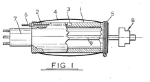
- the illustrated perforating unit comprises a rigid tubular body 1 through which an air passage 2 extends to a radial opening 3.
- An inflatable sheath-like tubular bag 4 is clamped at its ends by clips 5.
- the bag 4 can be inflated by supplying compressed air to the passage 2 via a line 6, the compressed air entering the enclosed space between the bag 4 and the cylindrical surface of the body 1 via opening 3.
- a hydraulic motor 7 is rigidly supported on one end of the tubular body and a cutting head 8 on the other end.
- the hydraulic motor is connected is supported/by means not shown to a shaft 9 supporting the cutting head such that the motor can simultaneously rotate the head 8 and advance the shaft 9 out of the body 1.
- the perforating is inserted into a branch pipe with the cutting head 8 retracted and propelled by any suitable means, e.g. by rodding, into contact with the liner to be cut.
- the bag 4 is inflated to lock the body in position and the cutting head 8 is rotated and advanced to cut the liner. After completion of the cutting operation the cutting head 8 is withdrawn and the bag is deflated. The perforating unit is then withdrawn.
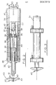
- perforating unit shown in Fig. 2 comprises a cylinder 31 extending between front and rear walls 32, 33. Behind the cylinder 31 is a hydraulic motor 34 with input and output connections 35, 36 for hydraulic fluid. A sheath 37 of resilient material envelopes the unit and is held in position by clips 38. Slidably mounted the cylinder 31 is a piston 39 integral with within a hollow shaft 40 which projects through an opening in the front wall 32 to end in a screw- threaded spigot 41.
- a cutting head 42 has a tapped socket 43 which fits onto the spigot 41.
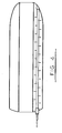
- the cutting head 42 is of cruciform shape as seen from the left in Fig. 2 and each of its four arms carries a replaceable cutting blade 43 the depth of penetration of which is indicated by dotted line.
- the outer end of each blade also has a rearwardly directed cutting portion for the purpose described below.
- An intermediate shaft 44 is slidably but non-rotably engaged in the piston 39, e.g. by means of splines or, as shown, by cooperating flats on the shaft 44 and the bore in the piston 39.
- the shaft 44 is journalled in a bearing 45 of the end wall 33 and is connected at its rear end to one half of a universal coupling 46 the other half of which is fixed to the output shaft 47 of the hydraulic motor 34.
- Flexible hydraulic pipes 48, 49 lead to front and rear compartments respectively of the cylinder 31. When one of these pipes delivers hydraulic fluid under pressure to the respective cylinder compartment the other pipe drains fluid from its compartment.
- the perforating unit of Fig. 2 operates in a similar fashion to that illustrated in Fig. 1.
- the output shaft 47 of the hydraulic motor 34 imparts a rotary motion to the cutting head 42 by means of the universal coupling 46, intermediate shaft 44 and hollow shaft 40.
- the rotating cutting head 42 can be advanced by pressurizing the rear cylinder compartment by means of the pipe 49.
- the cutting head 42 is retracted by pressurizing the front cylinder compartment by means of the pipe 48. Retraction of the cutting head 42 is facilitated by the rearwardly directed cutting portions of the cutting blades 43 enabling the blades to cut their way out of the liner after penetration of the cutting head 42 in to the liner.
- Fig. 3 is substantially the same as that of Fig. 2 but in this case the overall length of the unit is less and it is not necessary to couple the motor to the cylinder so as to facilitate negotiation of bends in the branch pipe. Accordingly the motor 34 is integral with the remainder of the body.
- Figs. 2 and 3 may be moved into position by any convenient means, e.g. rods.
- Certain of the features of the designs described above also facilitate the cutting operation when the perforating unit is in position. Thus, jamming of the unit in the pipe reduces or prevents vibration of the unit.
- the facility for advancing the cutting head into engagement with and through the plastics liner makes it easier to cut the liner on the slant, i.e. at an angle other than a right angle as a result of the branch pipe meeting the main pipe at an oblique angle.
- Another feature of importance in this context is the conical configuration of the cutting head whereby the liner is cut or shredded radially outwardly from a central point.
- the inflatable plug comprises an elongate air bag having a double skin defining an air chamber of annular cross-section.
- the outer skin is made of relatively flexible material whereas the inner skin is made of relatively rigid material so as to define a central passageway extending the full length of the air bag.
- the bag has a hollow flexible spine with perforations along its length. The rear end of the spine is provided with a screw connection for attaching the air bag to a hollow rod for pushing the bag into position and passing compressed air into the bag through the hollow spine.
- the plug is positioned when the air bag is fully deflated so as to lie completely flat.
- the plug is rodded along the branch pipe and through the opening in the liner until the front end of the spine contacts the opposite wall of the liner.
- the air bag is then retracted a predetermined distance to position the bag accurately in the opening.
- Compressed air from a compressor on the surface is then passed along the rod and into the air bag via the spine.
- Grout introduced under pressure between the main sewer wall and the liner is therefore unable to escape either into the branch pipe or into the interior of the liner.
- the air bag When the grout has set the air bag is simply deflated and the plug removed. It will be appreciated that it may be many hours before the plug can be removed and it is an important feature of the present design that the central passageway permits continued flow of fluid from the branch pipe into the main pipe while the plug is in position. Although this feature is important it is not essential and it is within the scope of the invention to provide an inflatable plug not having such a passageway and which therefore obstructs flow of fluid between the branch pipe and the main pipe when the plug is in position.
- the bag may comprise a single skin but as with the previous embodiment this will be fully flexible so that the bag lies flat when deflated. The absence of any rigid components in the outer wall of the plug facilitates the negotiation of bends in narrow pipes.
- the flexible spine extends within the central passageway rather than between the inner and outer skins.
Landscapes
- Engineering & Computer Science (AREA)
- Mechanical Engineering (AREA)
- General Engineering & Computer Science (AREA)
- Pipe Accessories (AREA)
Applications Claiming Priority (4)
| Application Number | Priority Date | Filing Date | Title |
|---|---|---|---|
| GB8112547 | 1981-04-23 | ||
| GB8112547 | 1981-04-23 | ||
| GB8120319 | 1981-07-01 | ||
| GB8120319 | 1981-07-01 |
Publications (1)
| Publication Number | Publication Date |
|---|---|
| EP0063919A1 true EP0063919A1 (fr) | 1982-11-03 |
Family
ID=26279219
Family Applications (1)
| Application Number | Title | Priority Date | Filing Date |
|---|---|---|---|
| EP82302049A Withdrawn EP0063919A1 (fr) | 1981-04-23 | 1982-04-21 | Canalisations |
Country Status (3)
| Country | Link |
|---|---|
| US (1) | US4434815A (fr) |
| EP (1) | EP0063919A1 (fr) |
| CA (1) | CA1179281A (fr) |
Cited By (4)
| Publication number | Priority date | Publication date | Assignee | Title |
|---|---|---|---|---|
| WO1987005984A1 (fr) * | 1986-03-25 | 1987-10-08 | Danby Pty. Ltd. | Remise en etat des connexions d'embranchement laterales dans des egouts ou des conduites regarnis |
| GB2192442A (en) * | 1986-07-11 | 1988-01-13 | Tracey Stephen | Lining a duct |
| FR2718665A1 (fr) * | 1994-04-15 | 1995-10-20 | Stolt Comex Seaway | Outil de découpe de tuyauterie immergée par jet abrasif. |
| EP2461080A3 (fr) * | 2010-12-01 | 2015-12-30 | Martin Schwalm | Manchon destiné à l'habillage de la zone de passage entre une conduite d'eau principale et un branchement individuel se jetant dans la conduite principale |
Families Citing this family (7)
| Publication number | Priority date | Publication date | Assignee | Title |
|---|---|---|---|---|
| US4520524A (en) * | 1984-03-26 | 1985-06-04 | Long Jr Charles A | Remotely controlled hydraulic cleaner apparatus |
| US4779496A (en) * | 1986-03-21 | 1988-10-25 | Westinghouse Electric Corp. | Tube cutting apparatus and method |
| US4845896A (en) * | 1987-02-24 | 1989-07-11 | Failure Analysis Associates | Surface sampling device |
| US6990879B2 (en) * | 2003-12-29 | 2006-01-31 | Rubino Daniel L | Drain line re-perforator device |
| US9295488B2 (en) | 2012-08-09 | 2016-03-29 | Wilson T. Asfora | Joint fusion |
| DE102015218600A1 (de) * | 2015-09-28 | 2017-03-30 | Bayerische Motoren Werke Aktiengesellschaft | Verfahren zur Bestimmung eines Mischungsverhältnisses von n organischen, mischbaren Komponenten in einem Gemisch dieser Komponenten und Verwendung eines anorganischen Markers |
| CN115289314B (zh) * | 2022-06-16 | 2023-09-05 | 广州市畅通管道工程有限公司 | 一种紫外光原位固化管道修复方法 |
Citations (3)
| Publication number | Priority date | Publication date | Assignee | Title |
|---|---|---|---|---|
| US3618639A (en) * | 1969-11-24 | 1971-11-09 | Cues Inc | Packer for sealing pipe leaks |
| US3835889A (en) * | 1972-03-31 | 1974-09-17 | Halliburton Co | Expandable pipeline plug |
| US3841355A (en) * | 1972-06-16 | 1974-10-15 | G Laner | Pipe plugging tool |
Family Cites Families (26)
| Publication number | Priority date | Publication date | Assignee | Title |
|---|---|---|---|---|
| US1941222A (en) | 1929-12-14 | 1933-12-26 | Sun Oil Co | Tube cleaning noise-silencer |
| US2742259A (en) | 1953-04-06 | 1956-04-17 | Cormack E Boucher | Conduit tractor |
| GB1116784A (en) | 1966-07-14 | 1968-06-12 | C W Fuelling Inc | Pipe cleaning apparatus |
| CH490900A (de) | 1967-06-28 | 1970-05-31 | Arx Paul Von | Vorrichtung, mit deren Hilfe die Innenwand eines Rohres gereinigt und/oder mit einem Schutzanstrich versehen werden kann |
| US3587194A (en) | 1968-08-02 | 1971-06-28 | Champion Corp | Tap cutter |
| IL33199A (en) | 1968-11-04 | 1972-10-29 | Mills D | Pipe relining method and apparatus |
| GB1243613A (en) | 1969-08-08 | 1971-08-25 | Tate Pipe Lining Process Ltd | Improvements in or relating to machines for internally sealing pipe joints or flaws |
| CA939459A (en) | 1970-05-25 | 1974-01-08 | Roy C. Latall | Hydraulic sewer pipe line cleaner |
| US3732625A (en) | 1970-10-12 | 1973-05-15 | Williamson Inc T | Pipeline pig |
| US3762446A (en) | 1970-12-08 | 1973-10-02 | Minnesota Mining & Mfg | Method and device for internally locating and sealing pipeline leaks |
| US3740785A (en) | 1971-07-14 | 1973-06-26 | Brien Mfg Co O | Hydraulic sewer pipeline cleaner |
| FR2242657B1 (fr) | 1973-08-27 | 1976-05-07 | Petroles Cie Francaise | |
| US3882565A (en) | 1973-11-30 | 1975-05-13 | Lawrence F Irwin | Spring feed device |
| US3899265A (en) | 1973-12-27 | 1975-08-12 | Harsco Corp | Method and apparatus to perforate pipe |
| US3950461A (en) | 1974-05-31 | 1976-04-13 | Nipak, Inc. | Pipe repair apparatus and method |
| GB1516307A (en) | 1974-09-09 | 1978-07-05 | Babcock & Wilcox Ltd | Apparatus for conveying a device for inspecting or performing operations on the interior of a tube |
| SU519522A1 (ru) | 1974-11-05 | 1976-06-30 | Государственное Специальное Конструкторское Бюро По Ирригации | Рабочий орган машины дл очистки дрен |
| GB1501971A (en) | 1975-01-20 | 1978-02-22 | Ross Lar | Method and apparatus for cleaning the inside of long cylindrical chambers |
| CA1035019A (fr) | 1975-11-12 | 1978-07-18 | Patrick C. Porter | Racleur a accelerometre |
| CH594848A5 (fr) | 1976-02-24 | 1978-01-31 | Sigel Gfeller Alwin | |
| GB1534780A (en) | 1976-05-11 | 1978-12-06 | Trans Canada Pipelines Ltd | Pipeline limit dent detector |
| GB1565049A (en) | 1976-12-16 | 1980-04-16 | British Gas Corp | Pipeline inspection vehicles |
| US4197908A (en) | 1978-04-06 | 1980-04-15 | Underground Surveys Corporation | Apparatus for porting a side wall of a conduit from interiorly thereof |
| FR2435974A1 (fr) | 1978-09-15 | 1980-04-11 | Entreprises Soc Gle | Procede et dispositif pour le debouchage de gaines obturees |
| US4245970A (en) | 1978-10-04 | 1981-01-20 | St Onge Henri S | Apparatus having a tubular inflatable bladder and a grout dispensing nozzle for connecting lateral branches to a relined main |
| GB2034431A (en) | 1978-11-02 | 1980-06-04 | Sewertech Ltd | Pipe cleaner |
-
1982
- 1982-04-21 EP EP82302049A patent/EP0063919A1/fr not_active Withdrawn
- 1982-04-22 CA CA000401501A patent/CA1179281A/fr not_active Expired
- 1982-04-22 US US06/370,750 patent/US4434815A/en not_active Expired - Fee Related
Patent Citations (3)
| Publication number | Priority date | Publication date | Assignee | Title |
|---|---|---|---|---|
| US3618639A (en) * | 1969-11-24 | 1971-11-09 | Cues Inc | Packer for sealing pipe leaks |
| US3835889A (en) * | 1972-03-31 | 1974-09-17 | Halliburton Co | Expandable pipeline plug |
| US3841355A (en) * | 1972-06-16 | 1974-10-15 | G Laner | Pipe plugging tool |
Cited By (5)
| Publication number | Priority date | Publication date | Assignee | Title |
|---|---|---|---|---|
| WO1987005984A1 (fr) * | 1986-03-25 | 1987-10-08 | Danby Pty. Ltd. | Remise en etat des connexions d'embranchement laterales dans des egouts ou des conduites regarnis |
| US4893389A (en) * | 1986-03-25 | 1990-01-16 | Peter Allen | Reinstatement of lateral branch connections in relined sewers or pipes |
| GB2192442A (en) * | 1986-07-11 | 1988-01-13 | Tracey Stephen | Lining a duct |
| FR2718665A1 (fr) * | 1994-04-15 | 1995-10-20 | Stolt Comex Seaway | Outil de découpe de tuyauterie immergée par jet abrasif. |
| EP2461080A3 (fr) * | 2010-12-01 | 2015-12-30 | Martin Schwalm | Manchon destiné à l'habillage de la zone de passage entre une conduite d'eau principale et un branchement individuel se jetant dans la conduite principale |
Also Published As
| Publication number | Publication date |
|---|---|
| US4434815A (en) | 1984-03-06 |
| CA1179281A (fr) | 1984-12-11 |
Similar Documents
| Publication | Publication Date | Title |
|---|---|---|
| US4434815A (en) | Pipework | |
| EP0411278B1 (fr) | Procédé et dispositif pour la destruction d'une conduite enterrée | |
| US5960882A (en) | Dual-ended apparatus for cutting openings in lined conduits | |
| US4893389A (en) | Reinstatement of lateral branch connections in relined sewers or pipes | |
| HK105388A (en) | A device and method for removing irregularities in or enlarging an underground duct | |
| IE56954B1 (en) | Main bursting tool | |
| WO2001031241A1 (fr) | Procede et appareil permettant de tester des installations de plomberie | |
| US5527133A (en) | Tool for a sewer robot | |
| US4298230A (en) | Tunnelling apparatus | |
| GB2113126A (en) | Remotely controlled internal pipeline cutting apparatus | |
| US5979276A (en) | Skiving apparatus and methods | |
| JP6395313B2 (ja) | コンクリート構造体の削孔部の修復方法および修復装置 | |
| US5515886A (en) | Method and apparatus for repairing a junction pipe connection to a main pipe | |
| GB2386767A (en) | Overdrill for trenchless removal of buried tubing. | |
| US3102442A (en) | An acorn-shaped cutter bit | |
| EP0190502B1 (fr) | Outil pour la rupture de conduits | |
| JPH036396B2 (fr) | ||
| JP3477590B2 (ja) | 補修材穿孔機 | |
| WO2005014967A1 (fr) | Dispositif d'eclatement de conduite dote d'un element d'eclatement spherique | |
| JPS61179724A (ja) | 管内面ライニングチユ−ブの分岐孔検知開孔装置 | |
| EP1144797B1 (fr) | Procede de montage d'un sabot de tubage sur un appareil de forage | |
| DE2408953C2 (de) | Vorrichtung zum Anbohren einer Rohrleitung, insbesondere einer unterirdischen Abwasserleitung | |
| JP7703468B2 (ja) | 管切断方法および管内面切削装置 | |
| DE102021118185B4 (de) | Verfahren und Bohrkopf zur Reparatur einer Anschlussleitung im Erdreich, insbesondere für einen Hausanschluss | |
| JP3106468B2 (ja) | 旧管更新装置 |
Legal Events
| Date | Code | Title | Description |
|---|---|---|---|
| PUAI | Public reference made under article 153(3) epc to a published international application that has entered the european phase |
Free format text: ORIGINAL CODE: 0009012 |
|
| AK | Designated contracting states |
Designated state(s): AT BE CH DE FR GB IT LU NL SE |
|
| 17P | Request for examination filed |
Effective date: 19830110 |
|
| STAA | Information on the status of an ep patent application or granted ep patent |
Free format text: STATUS: THE APPLICATION IS DEEMED TO BE WITHDRAWN |
|
| 18D | Application deemed to be withdrawn |
Effective date: 19850507 |
|
| RIN1 | Information on inventor provided before grant (corrected) |
Inventor name: FLAHERTY, THOMAS Inventor name: PRICE, RICHARD HUW |