EP0063926A2 - Schachlerngerät - Google Patents
Schachlerngerät Download PDFInfo
- Publication number
- EP0063926A2 EP0063926A2 EP82302067A EP82302067A EP0063926A2 EP 0063926 A2 EP0063926 A2 EP 0063926A2 EP 82302067 A EP82302067 A EP 82302067A EP 82302067 A EP82302067 A EP 82302067A EP 0063926 A2 EP0063926 A2 EP 0063926A2
- Authority
- EP
- European Patent Office
- Prior art keywords
- square
- playing
- switches
- display
- squares
- Prior art date
- Legal status (The legal status is an assumption and is not a legal conclusion. Google has not performed a legal analysis and makes no representation as to the accuracy of the status listed.)
- Ceased
Links
Images


Classifications
-
- G—PHYSICS
- G09—EDUCATION; CRYPTOGRAPHY; DISPLAY; ADVERTISING; SEALS
- G09B—EDUCATIONAL OR DEMONSTRATION APPLIANCES; APPLIANCES FOR TEACHING, OR COMMUNICATING WITH, THE BLIND, DEAF OR MUTE; MODELS; PLANETARIA; GLOBES; MAPS; DIAGRAMS
- G09B19/00—Teaching not covered by other main groups of this subclass
- G09B19/22—Games, e.g. card games
Definitions
- any playing piece in a chess game depends upon a number of factors, including the position of the square on which the playing piece is placed, the functional character of the playing piece, i.e. whether it be a King or a Queen, a Knight etc., and the positions of intervening pieces, the last two being variable factors.
- any signalling system for indicating the squares under attack from all possible positions on the board must have a very large number of possible signalling channels, and such channels must be capable of being selectively activated in successively different combinations as the game proceeds.
- a chess instruction apparatus comprising a playing area comprising an array of playing squares and a plurality of playing pieces of opposing colours, the apparatus being characterised by:
- Apparatus in accordance with the invention may thus be considered as comprising a chessboard with display means operable by the playing pieces for indicating which squares are controlled, i.e. under attack, by such playing pieces.
- display means operable by the playing pieces for indicating which squares are controlled, i.e. under attack, by such playing pieces.
- the apparatus preferably includes a mode selector switch operable to enable the display circuits in either of two operating modes whereby a user can readily ascertain which squares are controlled by pieces of one colour and which squares are controlled by pieces of the opposing colour.
- the two operating modes of a display circuit are most conveniently provided by having a pair of indicator lamps, readily distinguishable from one another by colour, which can be selectively enabled by the mode selector switch.
- colour is used in a broad “heraldic” sense to denote a characteristic feature by which the opposing sets of playing pieces are distinguishable from one another. That is to say, playing pieces said to be of opposing colours need not in fact be of different colours provided they are in some way distinguishable from one another by a user.
- function is used to denote the pattern of permissible moves characteristic of a given playing piece.
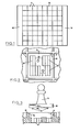
- a chessboard provides a conventional playing area 10 comprising a square array of sixty-four playing squares 11.
- Support structure 12 shown at the sides of the playing area supports circuit boards (not shown) beneath the playing area, these boards carrying the hardware of signalling circuitry to be described hereinafter.
- each square 11 is bounded by a peripheral step 13, which defines a locating recess 14 for locating a playing piece 15.
- Each playing piece 15 has a base portion 16 conforming to the shape of the recess.
- the conforming shapes of the recess and the playing piece are such that the piece can only be inserted in one way, for example as illustrated in Figures 2 and 3, by providing a stop 17 at one corner of the recess and a complementary cut-off at the appropriate corner of each playing piece base portion.
- each square Located within each square are a number of switches 18, the switches being arranged in a predetermined spacial configuration which is the same for each square.
- Each playing piece 15 provides a set of switch actuating members in the form of pins or short projections 19 extending from the underside of its base portion and positioned so that, when the playing piece is properly located on a square, each pin 19 will engage the particular switch 18 with which it is aligned and thus actuate the switch.
- the switches are thus actuated selectively according to the number and positions of the pins 19 on the base portion.
- These are arranged differently for different playing pieces in such a way that, for each playing piece, the configuration of switch actuating members corresponds uniquely to the colour and the function of the playing piece.
- the selective actuation of the switches 18 serves to decode the configuration of switch actuating members thereby to identify the particular piece.
- the switches may suitably be microswitches (such as Archer Switches Catalogue No. 275-016), each providing a normally open contact which is closed by actuation of the switch, a normally closed contact which is opened by actuation of the switch, and a common terminal.
- the switches 18 of each square being selectively actuated as described above, initiate the transmission of a signal denoting the presence of a particular playing piece on the square. This signal is received at various stations assigned to the respective squares which are under direct attack by the playing piece, so as to operate display circuits. Since the playing piece may be of either colour, e.g. black or white, each display circuit preferably has two modes of operation which are selected according to the colour of the playing piece.
- the display means is represented by a pair of differently coloured lamps 20, 21 located within each square, the lamps being selectively operable as hereinafter described to denote that the square is under attack by a playing piece of the respective colour.
- Figure 4 shows the electrical connections to the terminals of the switches 18 and the lamps 20, 21.
- the lamp terminals are denoted by the letters x, x and y, y;
- the common terminals of the switches are denoted by the letter c;
- the terminals of the normally closed contacts and of the normally open contacts are denoted by the letters a and b respectively. It will be seen that each switch has one terminal which is not connected.
- the configuration of eleven microswitches shown in Figure 4 comprises a pair of normally open “control” switches 18a, 18b which are selectively operable by each playing piece according to colour; five normally open “function” switches 18c, 18d, 18e, 18f, and 18g which are selectively operable by playing pieces according to function, and four "interruptor” switches 18h, 18i, 18j, and 18k which are operated by all playing pieces regardless of colour and function of the pieces.
- the switch configuration is the same for all squares, the interruptor switches of squares adjacent to the edges of the playing area are not connected as they serve no purpose for such squares.
- the Queen duplicates the functions of both a Rook and a Bishop, and so only five function switches are required.
- the switches 18 of each square constitute a system of gates interconnected to provide the signalling circuit of the square.
- the control switches 18a, 18b serve to select the appropriate display mode according-to the colour of the playing piece located on the square.
- the purpose of the function switches is to signal the presence of a detected playing piece to all squares controlled by the playing piece, by gating the various possible current paths through a signalling network interconnecting the display circuits with a current supply.
- the purpose of the interruptor switches is to interrupt signals which would otherwise be transmitted to squares protected by intervening playing pieces. Each interruptor switch must therefore be operated by any such intervening piece. A discovered attack by movement of an intervening piece from its position will be displayed by release of the interruptor switch to close the relevant current path.
- FIG. 5 is a wiring diagram of the signalling circuitry of an individual square.
- Each signalling circuit has a bus 22 connected via the control switch 18a to a current source 23 via a normally open, momentarily operated switch 23', and alternatively connected via the control switch 18b and a normally open, momentarily operated switch 24' to a current source 24.
- the switches 23' and 24' are operated manually by the players.
- the bus 22 is connected via the function switches 18c, 18d, 18e, 18f, and 18g to the node points of star connected sets of diodes 25, each set being connected to a corresponding set of buses shown at terminals 26.
- the respective systems each comprising a set of diodes 25 and output buses 26 are indicated by the letters A, B, C, D, E, F, G.
- Signals generated by the signalling circuit are received by the display circuits of related squares as will be described subsequently.
- operation of the function switch 18c will activate the output buses 26 of the systems A and B.
- the output buses of system A are connected to the input terminals of the display circuits of all squares lying on a diagonal containing the controlling square.
- the output buses of system B are connected to the input terminals of the display circuits of all squares lying on the other diagonal.
- the function switch 18d is operated by a Queen and a Rook. Therefore, the output buses 26 of system C are connected to the input terminals of the display circuits of all squares on the same rank as the controlling square, and the output buses of system D are connected to the input terminals of the display circuits of all squares in the same file.
- the function switch 18e is operated by a King and by a Pawn.
- the output terminals of system E are connected to the display input terminals of two diagonally adjacent forward squares only.
- the function switch 18f is operated only by a King.
- the output buses 26 of the system F are therefore connected to the display input terminals of adjacent squares other than the two diagonally adjacent squares controlled by system E.
- the function switch 18g is controlled by a Knight.
- a Knight can control up to eight squares, the input terminals of the display circuits of those squares are connected respectively to the output buses 26 of system G.
- pairs of output buses of systems A, B, C, and D are interconnected by the interruptor switches 18h, 18i, 18j and 18k. These switches serve to interconnect the display circuits of squares in a row, or a file, or a diagonal, while permitting the interruption of a signalling path by an intervening piece.
- each display circuit has twelve pairs of input terminals 27, each pair of input terminals being connected to a respective pair of output buses of the signalling circuits of potentially controlling squares.
- each pair of input terminals 27 will receive an input signal from a related square on which a playing piece is located.
- the input terminals 27 are connected through diodes 28 to a bus 29.
- the bus 29 When a signal is received on any input terminal, the bus 29 will be at a negative potential, being connected to the current source 23 or 24. (The current sources 23 and 24 are, of course, common to all the signalling circuits).
- a received signal will activate the display circuit 30, which includes the two indicator lamps 20, 21. These lamps are activated from respective current sources 31, 32 via the contacts 33', 34', of respective self-holding relays 33, 34.
- the current source 31 is connected to relay contact 33' via normally closed contacts of a momentarily open switch 31'.
- the current source 32 is connected to relay contact 34' via normally closed contacts of a momentarily open switch 32'.
- Each player before making a new move, presses a respective one of the switches 31', 32' thereby to clear the display lamp 20 or 21 which indicates control of the particular square by his pieces.
- the relay 33 or 34 On receipt of a signal, the relay 33 or 34 will be operated according to the position of a relay contact 35' of a relay 35.
- the position of the contact 35' depends upon the setting of a mode selector switch 36 which determines whether or not the relay 35 is to be energized from a current source 37.
- the switch 36 will be set to the open or closed position according to whether black or white is about to make a move, thereby enabling the appropriate lamp 20 or 21 to receive the signal relating to that move. Since the relay coils 33, 34 are in parallel with the lamps 20, 21, the circuits of these relays are self-holding and so the existing board display will remain even though signal current only flows while the momentary switch 23' or 24' is being operated.
- this relates to the interconnections of squares contained in a common rank, file or diagonal.
- a system comprising a portion of its signalling circuit containing the relevant function switch and output buses, and the display circuit 30 with the relevant pair of input terminals.
- the systems of the eight squares are identical and are numbered 1 to 8 respectively.
- the overall circuit is the same for each rank, file and diagonal, except that for all but two diagonals there will be fewer than eight squares.
- the squares 1 to 8 lie on a major diagonal, the relevant function switches being the switches 18c and the relevant output buses being those of the diode system A.
- FIG 7 The system of interconnections illustrated in Figure 7 and described above is applicable to all signalling circuits controlled by the function switches 18c, 18d.
- the system of interconnections of signalling circuits controlled by the function switches 18e, 18f and 18g is illustrated in Figure 8. Since a Pawn can control one pair of diagonally adjacent squares, and a King can control four pairs of adjacent squares, and a Knight can control four pairs of squares, it is possible to represent each signalling circuit controlled by one of these pieces by an interconnection between the transmitting circuit of a controlling square and the display circuits of one pair of controlled squares.
- Figure 8 illustrates, for simplicity, the essentials of one such elemental interconnection. The three squares are numbered 1', 2' and 3' for convenience.
- the controlling playing piece is a Pawn. Therefore we need to consider the signalling circuits controlled by the function switches 18e. If a Pawn is placed on the square 2', the control switch 18a or 18b of that square will be operated, depending upon the colour of the Pawn. The function switch 18e of square 2' will also be operated, thereby activating the output buses of system E for the square. Therefore, when the player signals, the display circuit 30 of squares 1' and 3' will be activated to indicate that those squares are controlled by the Pawn. If the square 2' is at the edge of the board, the operation will be the same except that there will be no display system corresponding to square 1' and only the display circuit 30 of square 3' will be operated.
- the function switch 18e is also operated by a King on the square, and its presence will be signalled in the same manner to the diagonally adjacent squares 1 1 and 3'. However, the presence of the King is also signalled to six other squares via three pairs of signalling circuits corresponding to that of Figure 8, this additional signalling being initiated by the function switch 18f of Figure 5. Thus, the presence of a King on a square is signalled by the operation of the function switches 18e and 18f to a maximum of eight squares by four pairs of signalling circuits. Similarly, the presence of a Knight on a square, by operation of the function switch 18g, and when the player signals, is signalled to the display circuit of a maximum of eight squares by way of four pairs of signalling circuits.
- the signalling requirements for all possible configurations of play will, in the light of the foregoing disclosure, be obvious to those who understand the game of chess.
- the signalling is accomplished by the selective gating of current paths through a circuit network, the network being reducable to a system of elemental circuit connections as described with reference to Figures 7 and 8.
Landscapes
- Business, Economics & Management (AREA)
- Engineering & Computer Science (AREA)
- Entrepreneurship & Innovation (AREA)
- Physics & Mathematics (AREA)
- Educational Administration (AREA)
- Educational Technology (AREA)
- General Physics & Mathematics (AREA)
- Theoretical Computer Science (AREA)
- Electrophonic Musical Instruments (AREA)
- Toys (AREA)
Applications Claiming Priority (2)
| Application Number | Priority Date | Filing Date | Title |
|---|---|---|---|
| US257337 | 1981-04-24 | ||
| US06/257,337 US4343609A (en) | 1981-04-24 | 1981-04-24 | Chess instruction apparatus |
Publications (2)
| Publication Number | Publication Date |
|---|---|
| EP0063926A2 true EP0063926A2 (de) | 1982-11-03 |
| EP0063926A3 EP0063926A3 (de) | 1983-04-13 |
Family
ID=22975890
Family Applications (1)
| Application Number | Title | Priority Date | Filing Date |
|---|---|---|---|
| EP82302067A Ceased EP0063926A3 (de) | 1981-04-24 | 1982-04-22 | Schachlerngerät |
Country Status (2)
| Country | Link |
|---|---|
| US (1) | US4343609A (de) |
| EP (1) | EP0063926A3 (de) |
Cited By (2)
| Publication number | Priority date | Publication date | Assignee | Title |
|---|---|---|---|---|
| GB2139905A (en) * | 1983-05-19 | 1984-11-21 | Rory Derek Albert Reid | Electronic chess game |
| FR2595836A1 (fr) * | 1986-03-11 | 1987-09-18 | Rothman Denis | Dispositif informatise de communication |
Families Citing this family (9)
| Publication number | Priority date | Publication date | Assignee | Title |
|---|---|---|---|---|
| DE3608148A1 (de) * | 1986-03-12 | 1987-09-24 | Schwab Technologieberatung | Anordnung zum ueberwachen und anzeigen von schachpartien |
| JPH07100079B2 (ja) * | 1989-03-31 | 1995-11-01 | 富士電子工業株式会社 | 自動判定機能を備えた遊技機 |
| GB8920204D0 (en) * | 1989-09-07 | 1989-10-18 | Saitek Ltd | Sensory games |
| US5121927A (en) * | 1991-03-15 | 1992-06-16 | Jones Michael J | Checkerboard game that activates water throwing device |
| AU6018494A (en) * | 1993-05-21 | 1994-12-20 | Arthur D. Little Enterprises, Inc. | User-configurable control device |
| JP4143158B2 (ja) * | 1997-04-16 | 2008-09-03 | 聯華電子股▲ふん▼有限公司 | データキャリア |
| US20050035545A1 (en) * | 2003-08-13 | 2005-02-17 | Yi-Fu Lee | Board for cross-and-circle game |
| US9672668B2 (en) | 2012-09-28 | 2017-06-06 | Mattel, Inc. | Keyed memory device to record input user signals and output recorded user signals |
| US9174116B2 (en) * | 2012-09-28 | 2015-11-03 | Intel Corporation | System for developing, managing, acquiring and playing electronic board games |
Family Cites Families (12)
| Publication number | Priority date | Publication date | Assignee | Title |
|---|---|---|---|---|
| US2679397A (en) * | 1951-12-01 | 1954-05-25 | Thacker Thomas Lindsay | Electrically controlled chess board |
| GB688186A (en) * | 1951-12-07 | 1953-02-25 | Thomas Lindsay Thacker | Improvements in and relating to chess boards |
| US3395463A (en) * | 1966-04-21 | 1968-08-06 | Donald G Worden | Chess machine |
| US3579856A (en) * | 1968-07-22 | 1971-05-25 | Frederick L Way | Auto-chess apparatus and punched card therefor |
| US3697076A (en) * | 1969-04-17 | 1972-10-10 | Charles B Vogel | Board game apparatus |
| US3683363A (en) * | 1970-12-03 | 1972-08-08 | Gleb Sergeevich Khlebutin | Device for demonstration of chess play |
| US3760404A (en) * | 1972-07-07 | 1973-09-18 | G Sergeevich | Chess game progress demonstration device |
| US3854725A (en) * | 1973-08-06 | 1974-12-17 | P Cluck | Electric chess game boards |
| US3888491A (en) * | 1974-03-19 | 1975-06-10 | Harvey B Bernard | Electronic chess board and display system |
| US3893671A (en) * | 1974-09-03 | 1975-07-08 | Robert C Gardner | Fiber optic chessboard |
| US4019745A (en) * | 1975-10-29 | 1977-04-26 | Enrique Mustelier | Electrical chess game |
| US4082285A (en) * | 1976-11-15 | 1978-04-04 | Bathurst David B | Electronic chess game |
-
1981
- 1981-04-24 US US06/257,337 patent/US4343609A/en not_active Expired - Fee Related
-
1982
- 1982-04-22 EP EP82302067A patent/EP0063926A3/de not_active Ceased
Cited By (2)
| Publication number | Priority date | Publication date | Assignee | Title |
|---|---|---|---|---|
| GB2139905A (en) * | 1983-05-19 | 1984-11-21 | Rory Derek Albert Reid | Electronic chess game |
| FR2595836A1 (fr) * | 1986-03-11 | 1987-09-18 | Rothman Denis | Dispositif informatise de communication |
Also Published As
| Publication number | Publication date |
|---|---|
| EP0063926A3 (de) | 1983-04-13 |
| US4343609A (en) | 1982-08-10 |
Similar Documents
| Publication | Publication Date | Title |
|---|---|---|
| US4343609A (en) | Chess instruction apparatus | |
| EP0935491B1 (de) | Computerspiel | |
| US3888491A (en) | Electronic chess board and display system | |
| US3560964A (en) | Keyboard unit | |
| US4391447A (en) | Electronic chess game | |
| US4391444A (en) | Electronic game providing formation changes and method | |
| US5855513A (en) | Electronic matching and position game | |
| US3863931A (en) | Electrical crossword puzzle | |
| US4850592A (en) | Mouse maze game | |
| US4633167A (en) | Tester for electrical joy stick controllers | |
| JPH07100079B2 (ja) | 自動判定機能を備えた遊技機 | |
| US3194560A (en) | Electrically operated game combination comprising an apertured game board and electrically conductive game pieces | |
| US3404889A (en) | Electrical game apparatus having multiple circuit paths to be selectively completed and interrupted by opposing players | |
| GB1591363A (en) | Electronic bowling scoring system with bus communication between manager console and lane score consoles | |
| CA1214877A (en) | Puzzle/game | |
| US3556525A (en) | Electric football game with offensive, defensive, and chance selection means | |
| US4080596A (en) | Bingo game indicator | |
| JPH01265983A (ja) | チエス教習用コンピユータゲーム装置 | |
| US3438628A (en) | Electrical game apparatus | |
| CA1171435A (en) | Chess instruction apparatus | |
| US4831219A (en) | Keyboard | |
| US4069597A (en) | Question and answer game | |
| US2860422A (en) | Multiple answer electrical quiz game | |
| US3563552A (en) | Logic game | |
| US3698180A (en) | Automatic chess time indicator |
Legal Events
| Date | Code | Title | Description |
|---|---|---|---|
| PUAI | Public reference made under article 153(3) epc to a published international application that has entered the european phase |
Free format text: ORIGINAL CODE: 0009012 |
|
| AK | Designated contracting states |
Designated state(s): DE FR GB |
|
| PUAL | Search report despatched |
Free format text: ORIGINAL CODE: 0009013 |
|
| AK | Designated contracting states |
Designated state(s): DE FR GB |
|
| 17P | Request for examination filed |
Effective date: 19830904 |
|
| STAA | Information on the status of an ep patent application or granted ep patent |
Free format text: STATUS: THE APPLICATION HAS BEEN REFUSED |
|
| 18R | Application refused |
Effective date: 19880516 |