EP0063941B2 - Cooling system for an internal combustion engine - Google Patents
Cooling system for an internal combustion engine Download PDFInfo
- Publication number
- EP0063941B2 EP0063941B2 EP82302121A EP82302121A EP0063941B2 EP 0063941 B2 EP0063941 B2 EP 0063941B2 EP 82302121 A EP82302121 A EP 82302121A EP 82302121 A EP82302121 A EP 82302121A EP 0063941 B2 EP0063941 B2 EP 0063941B2
- Authority
- EP
- European Patent Office
- Prior art keywords
- water
- coolant
- cooler
- temperature section
- coolant water
- Prior art date
- Legal status (The legal status is an assumption and is not a legal conclusion. Google has not performed a legal analysis and makes no representation as to the accuracy of the status listed.)
- Expired - Lifetime
Links
- 238000001816 cooling Methods 0.000 title claims description 33
- 238000002485 combustion reaction Methods 0.000 title claims description 9
- XLYOFNOQVPJJNP-UHFFFAOYSA-N water Substances O XLYOFNOQVPJJNP-UHFFFAOYSA-N 0.000 claims description 92
- 239000002826 coolant Substances 0.000 claims description 63
- 239000013505 freshwater Substances 0.000 claims description 36
- 239000013535 sea water Substances 0.000 claims description 11
- 239000000203 mixture Substances 0.000 claims 1
- 239000003570 air Substances 0.000 description 32
- 239000002918 waste heat Substances 0.000 description 8
- 239000007789 gas Substances 0.000 description 6
- 239000000498 cooling water Substances 0.000 description 2
- 230000003247 decreasing effect Effects 0.000 description 2
- 238000009434 installation Methods 0.000 description 2
- 150000003839 salts Chemical class 0.000 description 2
- 239000012080 ambient air Substances 0.000 description 1
- 230000001276 controlling effect Effects 0.000 description 1
- 238000010586 diagram Methods 0.000 description 1
- 239000000446 fuel Substances 0.000 description 1
- 238000010438 heat treatment Methods 0.000 description 1
- 230000001105 regulatory effect Effects 0.000 description 1
- 238000000926 separation method Methods 0.000 description 1
Images

Classifications
-
- F—MECHANICAL ENGINEERING; LIGHTING; HEATING; WEAPONS; BLASTING
- F02—COMBUSTION ENGINES; HOT-GAS OR COMBUSTION-PRODUCT ENGINE PLANTS
- F02B—INTERNAL-COMBUSTION PISTON ENGINES; COMBUSTION ENGINES IN GENERAL
- F02B29/00—Engines characterised by provision for charging or scavenging not provided for in groups F02B25/00, F02B27/00 or F02B33/00 - F02B39/00; Details thereof
- F02B29/04—Cooling of air intake supply
- F02B29/0406—Layout of the intake air cooling or coolant circuit
- F02B29/0437—Liquid cooled heat exchangers
- F02B29/0443—Layout of the coolant or refrigerant circuit
-
- F—MECHANICAL ENGINEERING; LIGHTING; HEATING; WEAPONS; BLASTING
- F01—MACHINES OR ENGINES IN GENERAL; ENGINE PLANTS IN GENERAL; STEAM ENGINES
- F01P—COOLING OF MACHINES OR ENGINES IN GENERAL; COOLING OF INTERNAL-COMBUSTION ENGINES
- F01P3/00—Liquid cooling
- F01P3/18—Arrangements or mounting of liquid-to-air heat-exchangers
-
- F—MECHANICAL ENGINEERING; LIGHTING; HEATING; WEAPONS; BLASTING
- F01—MACHINES OR ENGINES IN GENERAL; ENGINE PLANTS IN GENERAL; STEAM ENGINES
- F01P—COOLING OF MACHINES OR ENGINES IN GENERAL; COOLING OF INTERNAL-COMBUSTION ENGINES
- F01P3/00—Liquid cooling
- F01P3/20—Cooling circuits not specific to a single part of engine or machine
-
- F—MECHANICAL ENGINEERING; LIGHTING; HEATING; WEAPONS; BLASTING
- F01—MACHINES OR ENGINES IN GENERAL; ENGINE PLANTS IN GENERAL; STEAM ENGINES
- F01P—COOLING OF MACHINES OR ENGINES IN GENERAL; COOLING OF INTERNAL-COMBUSTION ENGINES
- F01P2050/00—Applications
- F01P2050/02—Marine engines
-
- F—MECHANICAL ENGINEERING; LIGHTING; HEATING; WEAPONS; BLASTING
- F01—MACHINES OR ENGINES IN GENERAL; ENGINE PLANTS IN GENERAL; STEAM ENGINES
- F01P—COOLING OF MACHINES OR ENGINES IN GENERAL; COOLING OF INTERNAL-COMBUSTION ENGINES
- F01P2060/00—Cooling circuits using auxiliaries
- F01P2060/02—Intercooler
-
- F—MECHANICAL ENGINEERING; LIGHTING; HEATING; WEAPONS; BLASTING
- F02—COMBUSTION ENGINES; HOT-GAS OR COMBUSTION-PRODUCT ENGINE PLANTS
- F02B—INTERNAL-COMBUSTION PISTON ENGINES; COMBUSTION ENGINES IN GENERAL
- F02B29/00—Engines characterised by provision for charging or scavenging not provided for in groups F02B25/00, F02B27/00 or F02B33/00 - F02B39/00; Details thereof
- F02B29/04—Cooling of air intake supply
- F02B29/0406—Layout of the intake air cooling or coolant circuit
- F02B29/0412—Multiple heat exchangers arranged in parallel or in series
-
- F—MECHANICAL ENGINEERING; LIGHTING; HEATING; WEAPONS; BLASTING
- F02—COMBUSTION ENGINES; HOT-GAS OR COMBUSTION-PRODUCT ENGINE PLANTS
- F02B—INTERNAL-COMBUSTION PISTON ENGINES; COMBUSTION ENGINES IN GENERAL
- F02B29/00—Engines characterised by provision for charging or scavenging not provided for in groups F02B25/00, F02B27/00 or F02B33/00 - F02B39/00; Details thereof
- F02B29/04—Cooling of air intake supply
- F02B29/045—Constructional details of the heat exchangers, e.g. pipes, plates, ribs, insulation, materials, or manufacturing and assembly
- F02B29/0462—Liquid cooled heat exchangers
-
- F—MECHANICAL ENGINEERING; LIGHTING; HEATING; WEAPONS; BLASTING
- F02—COMBUSTION ENGINES; HOT-GAS OR COMBUSTION-PRODUCT ENGINE PLANTS
- F02B—INTERNAL-COMBUSTION PISTON ENGINES; COMBUSTION ENGINES IN GENERAL
- F02B29/00—Engines characterised by provision for charging or scavenging not provided for in groups F02B25/00, F02B27/00 or F02B33/00 - F02B39/00; Details thereof
- F02B29/04—Cooling of air intake supply
- F02B29/0493—Controlling the air charge temperature
-
- Y—GENERAL TAGGING OF NEW TECHNOLOGICAL DEVELOPMENTS; GENERAL TAGGING OF CROSS-SECTIONAL TECHNOLOGIES SPANNING OVER SEVERAL SECTIONS OF THE IPC; TECHNICAL SUBJECTS COVERED BY FORMER USPC CROSS-REFERENCE ART COLLECTIONS [XRACs] AND DIGESTS
- Y02—TECHNOLOGIES OR APPLICATIONS FOR MITIGATION OR ADAPTATION AGAINST CLIMATE CHANGE
- Y02T—CLIMATE CHANGE MITIGATION TECHNOLOGIES RELATED TO TRANSPORTATION
- Y02T10/00—Road transport of goods or passengers
- Y02T10/10—Internal combustion engine [ICE] based vehicles
- Y02T10/12—Improving ICE efficiencies
Definitions
- the present invention relates to cooling systems specifically for marine internal combustion engines.
- FIG. 1 of the accompanying drawings One known form of air cooler for a marine diesel engine is illustrated in Figure 1 of the accompanying drawings and comprises a high temperature air inlet port 01, a low temperature air outlet port 02, a coolant sea water inlet port 03, a coolant sea water outlet port 04, cooling pipes 05, a high temperature section 08, and a low temperature section 09.
- the air cooler is divided into two, high temperature and low temperature sections 08 and 09 respectively, of which the low temperature section is for sea water cooling as described above, whilst the high temperature section 08, having inlet and outlet ports 06 and 07 respectively, is designed for water cooling.
- the temperature on the side of the coolant fresh water outlet port 07 can be relatively high and therefore used for heat utilization.
- this prior art system has the disadvantage that it is made somewhat complex due to the need to install standby lines for use upon stoppage of the marine engine, or interruption of waste heat utilization, or other causes.
- a cooling water system for a marine internal combustion engine is known from the Company MAK.
- a system which includes an air cooler divided into high and low temperature sections, each with respective coolant water inlet and outlet ports, and each being designed for fresh water cooling.
- the coolant water outlet port of the low temperature section of the air cooler is connected to the coolant water inlet port of a water jacket of the engine, whilst the coolant water inlet port of the high temperature section is connected to the coolant water outlet port of said water jacket.
- the system also includes a fresh water cooler for cooling said coolant water by heat exchange with sea water, a pump for circulating the coolant water and a water tank for storing the coolant water.
- such a cooling system is characterised in that said water tank and said water cooler are so connected that said fresh water can pass from said water tank to said water cooler, and in that the coolant water outlet port of said high temperature section of said air cooler is connected to an inlet to said water tank whereby, in operation of the system, said coolant water is circulted by said pump from said water tank through said fresh water cooler for initial cooling, then to said low temperature section, said water jacket, and said high temperature section, in that order, so that they are cooled in series by the coolant water without further cooling of said coolant water, whereby the coolant water is returned to said water tank at a sufficiently high temperature for heat utilization, and in that heat utilization means are associated with the water tank.
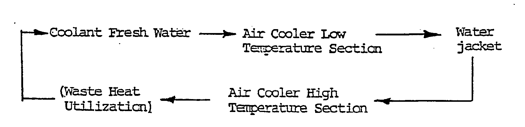
- the component parts of the cooling system are connected in the order of an outlet temperature with the lowest one placed first as illustrated in the following:
- An additional feature of the system resides in that a by-pass of coolant fresh water is provided for short-circuiting the air cooler low temperature section, and a control valve is provided in the by-pass for controlling the temperature of the coolant fresh water at the outlet port of the water jacket constant.
- the preferred cooling system comprises an air cooler 30 having an inlet port 1 for high temperature air, an outlet port 2 for low temperature air, a high temperature coolant section 3, and a low temperature coolant section 4.
- the system also includes a water jacket 5 of the engine, a tank 6 for coolant fresh water, a pump 7 for the coolant fresh water, and a fresh water cooler 8, provided between a delivery port of the pump 7 and an inlet port of the low temperature section 4 of the air cooler 30, for cooling the coolant fresh water by means of sea water fed through path 11.
- the system further includes a circulation pump 9 for circulating heated water from the tank 6 (for utilization of waste heat), to a group of heater equipments 10, and return to the tank.
- a control valve 12 for coolant fresh water temperature is provided at the confluence of a fresh water path 15 on the inlet side of the low temperature section 4 of the air cooler 30, and a by-pass 16 connecting a fresh water path 18 on the delivery side of the water pump 7 to said fresh water path 15 on the inlet side of the low temperature section 4 of the air cooler 30, which by-pass short-circuits the water cooler 8, said control valve serving to regulate the temperature of the fresh water on the inlet side of the low temperature section 4.
- a control valve 13 is provided for setting the temperature of the coolant fresh water, which valve is located in a bypass 17, which connects the fresh water path 18 on the delivery side of the water pump 7 to the fresh water path on the inlet side of the water jacket 5 so as to short-circuit both the water cooler 8 and the low temperature section 4 of the air cooler 30, the control valve 13 serving to regulate the temperature of the fresh water on the outlet side of the jacket 5.
- reference numeral 14 designates a standby heater (of steam type).
- Coolant fresh water is delivered from the water tank 6 with the aid of the water pump 7, and, after it has been regulated to an appropriate temperature by means of the control valve 12, it first cools the lower temperature section 4 of the air cooler 30, then cools the water jacket 5 of the engine, and subsequently cools the high temperature section 3 of the air cooler 30, as indicated by arrows.
- waste heat from the scavenged air passing through the air cooler 30 and from the water jacket is jointly collected by the coolant fresh water, and thus the final temperature of the coolant fresh water can be raised up to a sufficiently high temperature (although the temperature is equal to or lower than the air temperature at the high temperature air inlet port 1).
- This hot water is led to the coolant fresh water tank 6, from which it is circulated via the pump 9 to the various heater equipments 10, and the like in the ship as a heat source.
- the circulating water is subjected to heat exchange, and is thus lowered in temperature again, and is returned to the water tank 6 to be mixed with incoming high temperature coolant water, after which it is fed via the water pump to the fresh water cooler 8.
Landscapes
- Engineering & Computer Science (AREA)
- Chemical & Material Sciences (AREA)
- Combustion & Propulsion (AREA)
- Mechanical Engineering (AREA)
- General Engineering & Computer Science (AREA)
- Physics & Mathematics (AREA)
- Thermal Sciences (AREA)
- Heat Treatment Of Water, Waste Water Or Sewage (AREA)
- Lubrication Of Internal Combustion Engines (AREA)
Description
- The present invention relates to cooling systems specifically for marine internal combustion engines.
- One known form of air cooler for a marine diesel engine is illustrated in Figure 1 of the accompanying drawings and comprises a high temperature
air inlet port 01, a low temperatureair outlet port 02, a coolant seawater inlet port 03, a coolant seawater outlet port 04,cooling pipes 05, ahigh temperature section 08, and alow temperature section 09. - It has been common practice to cool an air cooler by means of sea water; hence, there is a possibility that salt may separate out from the coolant sea water in the
high temperature section 08. Because of this the coolant sea water temperature is permitted to rise at most up to about 50°C. In other words, although the quantity of waste heat dissipated in the sea water is relatively large, due to its relatively low temperature, the sea water cannot be utilized as a heat source in a ship, and therefore, it tends to be uselessly thrown away externally of the ship. - To meet this disadvantage, it has been proposed to utilize heated coolant as a heat source in a ship in the manner illustrated in Figure 2. Thus, as shown, the air cooler is divided into two, high temperature and
low temperature sections high temperature section 08, having inlet andoutlet ports water outlet port 07 can be relatively high and therefore used for heat utilization. However, this prior art system has the disadvantage that it is made somewhat complex due to the need to install standby lines for use upon stoppage of the marine engine, or interruption of waste heat utilization, or other causes. - It is also known, from British Patent Application 2057564, to provide in a cooling system for a pressure-charged internal combustion engine not specifically intended for use in a marine application an air cooler which is divided into high and low temperature sections, each section being supplied with fresh water coolant. In this system, the air cooler is arranged to cool the compressed charge intake air for the engine and the heat absorbed by each of the air cooler sections is dissipated to ambient air through associated fan-assisted radiators.
- A cooling water system for a marine internal combustion engine is known from the Company MAK. Thus, in their drawing No. 150.1-83.09.00-33, produced in 1977, there is shown a system which includes an air cooler divided into high and low temperature sections, each with respective coolant water inlet and outlet ports, and each being designed for fresh water cooling. The coolant water outlet port of the low temperature section of the air cooler is connected to the coolant water inlet port of a water jacket of the engine, whilst the coolant water inlet port of the high temperature section is connected to the coolant water outlet port of said water jacket. The system also includes a fresh water cooler for cooling said coolant water by heat exchange with sea water, a pump for circulating the coolant water and a water tank for storing the coolant water.
- This system makes full use of fresh water for coolant purposes in a marine internal combustion engine. However there has been an increasing demand for saving energy on board ship and in addition to the waste heat from exhaust gas which has been collected and utilized heretofore, there is also a need to collect and utilize the waste heat of scavenged air and jacket coolant water as efficiently as possible.
- It is a principal object of the present invention to provide a cooling system for a marine internal combustion engine generally of the kind known from the MAK drawing, in which the waste heat of scavenged air and jacket cooling water can be effectively collected and utilized.
- According to the present invention, such a cooling system is characterised in that said water tank and said water cooler are so connected that said fresh water can pass from said water tank to said water cooler, and in that the coolant water outlet port of said high temperature section of said air cooler is connected to an inlet to said water tank whereby, in operation of the system, said coolant water is circulted by said pump from said water tank through said fresh water cooler for initial cooling, then to said low temperature section, said water jacket, and said high temperature section, in that order, so that they are cooled in series by the coolant water without further cooling of said coolant water, whereby the coolant water is returned to said water tank at a sufficiently high temperature for heat utilization, and in that heat utilization means are associated with the water tank.
- Thus, in accordance with the invention, the component parts of the cooling system are connected in the order of an outlet temperature with the lowest one placed first as illustrated in the following:
- The cooling system of the invention enables the following advantages to be obtained:
- 1. fresh water is progressively raised in temperature as it passes through the cooling system and is collected at its highest temperature in the water tank for use as a heat source e.g. for a ship; thereby the steam generated by an exhaust gas economizer can be saved, and electric power generated by a turbine-generator can be increased by the corresponding amount;
- 2. a part of the coolant fresh water is reduced in temperature, and thereby the electric power required for a coolant water pump can be decreased; and
- 3. by carrying out high temperature jacket cooling, exhaust gas temperature can be raised, and so, electric power generated by a turbine-generator can be increased.
- An additional feature of the system resides in that a by-pass of coolant fresh water is provided for short-circuiting the air cooler low temperature section, and a control valve is provided in the by-pass for controlling the temperature of the coolant fresh water at the outlet port of the water jacket constant.
- The above-mentioned, and other features and objects of the present invention will become more apparent by reference to the following description of one preferred embodiment of the invention, taken in conjunction with the accompanying drawings, in which:
- Figures 1 and 2, respectively, are schematic views showing structures of known air coolers in the prior art, and.
- Figure 3 is a schematic system diagram of a cooling system for a marine internal combustion engine according to said preferred embodiment of the present invention.
- Referring now to Figure 3, the preferred cooling system comprises an
air cooler 30 having an inlet port 1 for high temperature air, anoutlet port 2 for low temperature air, a high temperature coolant section 3, and a low temperature coolant section 4. The system also includes a water jacket 5 of the engine, atank 6 for coolant fresh water, a pump 7 for the coolant fresh water, and afresh water cooler 8, provided between a delivery port of the pump 7 and an inlet port of the low temperature section 4 of theair cooler 30, for cooling the coolant fresh water by means of sea water fed throughpath 11. The system further includes acirculation pump 9 for circulating heated water from the tank 6 (for utilization of waste heat), to a group ofheater equipments 10, and return to the tank. Acontrol valve 12 for coolant fresh water temperature, is provided at the confluence of afresh water path 15 on the inlet side of the low temperature section 4 of theair cooler 30, and a by-pass 16 connecting afresh water path 18 on the delivery side of the water pump 7 to saidfresh water path 15 on the inlet side of the low temperature section 4 of theair cooler 30, which by-pass short-circuits thewater cooler 8, said control valve serving to regulate the temperature of the fresh water on the inlet side of the low temperature section 4. In addition, acontrol valve 13 is provided for setting the temperature of the coolant fresh water, which valve is located in abypass 17, which connects thefresh water path 18 on the delivery side of the water pump 7 to the fresh water path on the inlet side of the water jacket 5 so as to short-circuit both thewater cooler 8 and the low temperature section 4 of theair cooler 30, thecontrol valve 13 serving to regulate the temperature of the fresh water on the outlet side of the jacket 5. It is to be noted that in Figure 3reference numeral 14 designates a standby heater (of steam type). - In use the cooling system described above with reference to Figure 3 operates as follows:
- Coolant fresh water is delivered from the
water tank 6 with the aid of the water pump 7, and, after it has been regulated to an appropriate temperature by means of thecontrol valve 12, it first cools the lower temperature section 4 of theair cooler 30, then cools the water jacket 5 of the engine, and subsequently cools the high temperature section 3 of theair cooler 30, as indicated by arrows. - By employing the above-described arrangement, waste heat from the scavenged air passing through the
air cooler 30 and from the water jacket is jointly collected by the coolant fresh water, and thus the final temperature of the coolant fresh water can be raised up to a sufficiently high temperature (although the temperature is equal to or lower than the air temperature at the high temperature air inlet port 1). - This hot water is led to the coolant
fresh water tank 6, from which it is circulated via thepump 9 to thevarious heater equipments 10, and the like in the ship as a heat source. The circulating water is subjected to heat exchange, and is thus lowered in temperature again, and is returned to thewater tank 6 to be mixed with incoming high temperature coolant water, after which it is fed via the water pump to thefresh water cooler 8. - In the case of the above-described cooling system, the following advantages can be obtained:
- 1. By utilizing the heat of the coolant fresh water for various heating purposes in a ship, steam generated by an exhuast gas economizer can be saved by a corresponding amount, and can be fed to a turbine-generator. Thereby electric power generated by the turbine-generator can be increased 10-15%.
- 2. Since the final temperature of fresh coolant water can be high, the amount of the coolant water can be reduced, and hence the capacity of a coolant water pump and electric power necessitated therefore can be decreased.
- 3. By carrying out water jacket cooling with fresh water at a high temperature, the temperature of the exhuast gas is raised, and in this aspect also, electric power generated by a turbine-generator can be increased by 15-20%.
- 4. As the connecting line between the air cooler and water jacket can be realized by pipework within the engine, its installation in a ship can be simplified.
- 5. Installation in the case of a scoop cooling system, or a concentrated fresh water cooling system can be achieved advantageously and easily.
- 6. A standby line normally required when the main engine is stopped, or when waste heat utilization is interrupted, can be realised in a very simple manner.
- 7. Since a scavenged air temperature can be maintained relatively constant, the system provides for the use of poor quality fuel under low load conditions and for maintaining the same exhaust gas temperature in winter.
- 8. A salt separation phenomenon in the air cooler is eliminated.
Claims (5)
Applications Claiming Priority (2)
| Application Number | Priority Date | Filing Date | Title |
|---|---|---|---|
| JP56061920A JPS57179320A (en) | 1981-04-25 | 1981-04-25 | Cooler for internal-combustion engine |
| JP61920/81 | 1981-04-25 |
Publications (4)
| Publication Number | Publication Date |
|---|---|
| EP0063941A2 EP0063941A2 (en) | 1982-11-03 |
| EP0063941A3 EP0063941A3 (en) | 1983-04-13 |
| EP0063941B1 EP0063941B1 (en) | 1985-08-14 |
| EP0063941B2 true EP0063941B2 (en) | 1991-05-02 |
Family
ID=13185078
Family Applications (1)
| Application Number | Title | Priority Date | Filing Date |
|---|---|---|---|
| EP82302121A Expired - Lifetime EP0063941B2 (en) | 1981-04-25 | 1982-04-26 | Cooling system for an internal combustion engine |
Country Status (4)
| Country | Link |
|---|---|
| EP (1) | EP0063941B2 (en) |
| JP (1) | JPS57179320A (en) |
| DE (1) | DE3265368D1 (en) |
| DK (1) | DK155845C (en) |
Cited By (1)
| Publication number | Priority date | Publication date | Assignee | Title |
|---|---|---|---|---|
| DE19955302A1 (en) * | 1999-11-17 | 2001-05-23 | Deutz Ag | Liquid-cooled internal combustion engine |
Families Citing this family (7)
| Publication number | Priority date | Publication date | Assignee | Title |
|---|---|---|---|---|
| DE19727151A1 (en) * | 1997-06-26 | 1999-01-07 | Abb Daimler Benz Transp | Expansion tank and hydraulic system with expansion tank |
| DE102004024289A1 (en) * | 2004-05-15 | 2005-12-15 | Deere & Company, Moline | Cooling system for a vehicle |
| US20070227141A1 (en) * | 2006-03-31 | 2007-10-04 | Jiubo Ma | Multi-stage jacket water aftercooler system |
| CN109209601B (en) * | 2018-10-19 | 2021-04-13 | 安庆中船柴油机有限公司 | Cooling system and method for marine diesel engine |
| CN112211716A (en) * | 2020-09-14 | 2021-01-12 | 上海中船三井造船柴油机有限公司 | Condensate water discharge pipeline capable of being monitored for marine diesel engine |
| CN116906171B (en) * | 2023-06-19 | 2026-02-24 | 潍柴动力股份有限公司 | Intercooling post-temperature closed-loop adjusting system and method for ship machine staged cooling |
| CN116877386A (en) * | 2023-07-18 | 2023-10-13 | 南通中远海运川崎船舶工程有限公司 | Ship air compressor cooling water temperature control and automatic degassing system and method thereof |
Family Cites Families (7)
| Publication number | Priority date | Publication date | Assignee | Title |
|---|---|---|---|---|
| FR1499898A (en) * | 1966-03-02 | 1967-11-03 | Improvements to cooling systems for supercharged internal combustion engines | |
| CH457038A (en) * | 1966-04-28 | 1968-05-31 | Sulzer Ag | Plant for the utilization of waste heat from a reciprocating internal combustion engine to drive ships |
| GB1405086A (en) * | 1971-04-30 | 1975-09-03 | Mitsubishi Heavy Ind Ltd | Handrails for conveyors |
| DE2852076A1 (en) * | 1977-12-05 | 1979-06-07 | Fiat Spa | PLANT FOR GENERATING MECHANICAL ENERGY FROM HEAT SOURCES OF DIFFERENT TEMPERATURE |
| DE2825945A1 (en) * | 1978-06-14 | 1979-12-20 | Rudolf Dr Wieser | Supercharged vehicle engine cooling - has charge air cooler and engine and charge compressor jackets in closed cycle with pump and radiator |
| AU534896B2 (en) * | 1979-07-25 | 1984-02-23 | Black & Decker Incorporated | Three speed gear mechanism for a power tool |
| DE3044666A1 (en) * | 1980-11-27 | 1982-07-08 | Morath, Karl Günther, 6670 St. Ingbert | Small scale energy generation plant for domestic use - has heat transfer medium selectively fed through heat exchanger using combustion engine waste heat |
-
1981
- 1981-04-25 JP JP56061920A patent/JPS57179320A/en active Pending
-
1982
- 1982-04-23 DK DK182782A patent/DK155845C/en not_active IP Right Cessation
- 1982-04-26 DE DE8282302121T patent/DE3265368D1/en not_active Expired
- 1982-04-26 EP EP82302121A patent/EP0063941B2/en not_active Expired - Lifetime
Cited By (1)
| Publication number | Priority date | Publication date | Assignee | Title |
|---|---|---|---|---|
| DE19955302A1 (en) * | 1999-11-17 | 2001-05-23 | Deutz Ag | Liquid-cooled internal combustion engine |
Also Published As
| Publication number | Publication date |
|---|---|
| DK182782A (en) | 1982-10-26 |
| DK155845B (en) | 1989-05-22 |
| DE3265368D1 (en) | 1985-09-19 |
| EP0063941B1 (en) | 1985-08-14 |
| EP0063941A2 (en) | 1982-11-03 |
| JPS57179320A (en) | 1982-11-04 |
| EP0063941A3 (en) | 1983-04-13 |
| DK155845C (en) | 1989-10-02 |
Similar Documents
| Publication | Publication Date | Title |
|---|---|---|
| US5394854A (en) | Cooling system for a supercharged internal-combustion engine | |
| US4236492A (en) | Internal combustion engine having a supercharger and means for cooling charged air | |
| EP0916819B1 (en) | Locomotive engine cooling system | |
| US4911110A (en) | Waste heat recovery system for liquid-cooled internal combustion engine | |
| US3863612A (en) | Cooling system | |
| CA1170521A (en) | Apparatus for maintaining a diesel engine in restarting condition | |
| JPS5853172B2 (en) | Heat exchange equipment for charging air of internal combustion engines | |
| EP0750106B1 (en) | Utilization of low-value heat in a supercharged thermal engine | |
| US8695543B2 (en) | Internal combustion engine cooling unit | |
| EP0592500B1 (en) | Combined heat and power system | |
| KR102615752B1 (en) | Drive unit with integrated ORC | |
| EP0063941B2 (en) | Cooling system for an internal combustion engine | |
| GB2057564A (en) | Pressure-charged engine systems | |
| DE2625745B1 (en) | DIESEL COMBUSTION ENGINE SYSTEM FOR MARINE DRIVE | |
| US6347605B1 (en) | Moistening device for the inlet air of combustion engines | |
| US6145480A (en) | Turbocharged engine cooling system with two two-pass radiators | |
| SE425514B (en) | SETTING TO TEMPERATURE REGULATE A FRESHWATER COOLING SYSTEM FOR COMPRESSOR-LATED COMBUSTION ENGINES WITH AIR INTERNAL COOLER AND FRESHWATER COOLING SYSTEM ACCORDING TO THE SET | |
| KR100450436B1 (en) | And a fresh water cooling system | |
| FI92857B (en) | Cooling device for internal combustion engines | |
| US4049047A (en) | Liquid heat exchange system with separately compartmented make-up tanks | |
| US11649758B1 (en) | Systems and methods for control of engine cooling | |
| RU2027871C1 (en) | Liquid cooling system for turbocharged internal combustion engine of transport facility | |
| SU992765A2 (en) | Cooling system for i.c. engine with supercharging | |
| KR20190143218A (en) | Water-Cooled Heat Exchanger System | |
| EP2130761A2 (en) | Marine installation for energy recovery |
Legal Events
| Date | Code | Title | Description |
|---|---|---|---|
| PUAI | Public reference made under article 153(3) epc to a published international application that has entered the european phase |
Free format text: ORIGINAL CODE: 0009012 |
|
| AK | Designated contracting states |
Designated state(s): CH DE FR GB LI NL SE |
|
| PUAL | Search report despatched |
Free format text: ORIGINAL CODE: 0009013 |
|
| AK | Designated contracting states |
Designated state(s): CH DE FR GB LI NL SE |
|
| 17P | Request for examination filed |
Effective date: 19830202 |
|
| GRAA | (expected) grant |
Free format text: ORIGINAL CODE: 0009210 |
|
| AK | Designated contracting states |
Designated state(s): CH DE FR GB LI NL SE |
|
| REF | Corresponds to: |
Ref document number: 3265368 Country of ref document: DE Date of ref document: 19850919 |
|
| ET | Fr: translation filed | ||
| PLBI | Opposition filed |
Free format text: ORIGINAL CODE: 0009260 |
|
| 26 | Opposition filed |
Opponent name: KLOECKNER-HUMBOLDT-DEUTZ AG Effective date: 19860508 |
|
| NLR1 | Nl: opposition has been filed with the epo |
Opponent name: KLOECKNER-HUMBOLDT-DEUTZ AG |
|
| REG | Reference to a national code |
Ref country code: GB Ref legal event code: 746 |
|
| REG | Reference to a national code |
Ref country code: FR Ref legal event code: DL |
|
| PUAH | Patent maintained in amended form |
Free format text: ORIGINAL CODE: 0009272 |
|
| STAA | Information on the status of an ep patent application or granted ep patent |
Free format text: STATUS: PATENT MAINTAINED AS AMENDED |
|
| 27A | Patent maintained in amended form |
Effective date: 19910502 |
|
| AK | Designated contracting states |
Kind code of ref document: B2 Designated state(s): CH DE FR GB LI NL SE |
|
| REG | Reference to a national code |
Ref country code: CH Ref legal event code: AEN |
|
| ET3 | Fr: translation filed ** decision concerning opposition | ||
| NLR2 | Nl: decision of opposition | ||
| NLR3 | Nl: receipt of modified translations in the netherlands language after an opposition procedure | ||
| PGFP | Annual fee paid to national office [announced via postgrant information from national office to epo] |
Ref country code: SE Payment date: 19930419 Year of fee payment: 12 Ref country code: GB Payment date: 19930419 Year of fee payment: 12 |
|
| PG25 | Lapsed in a contracting state [announced via postgrant information from national office to epo] |
Ref country code: GB Effective date: 19940426 |
|
| PG25 | Lapsed in a contracting state [announced via postgrant information from national office to epo] |
Ref country code: SE Effective date: 19940427 |
|
| GBPC | Gb: european patent ceased through non-payment of renewal fee |
Effective date: 19940426 |
|
| EUG | Se: european patent has lapsed |
Ref document number: 82302121.7 Effective date: 19941110 |
|
| PGFP | Annual fee paid to national office [announced via postgrant information from national office to epo] |
Ref country code: FR Payment date: 19950411 Year of fee payment: 14 |
|
| PGFP | Annual fee paid to national office [announced via postgrant information from national office to epo] |
Ref country code: DE Payment date: 19950421 Year of fee payment: 14 |
|
| PGFP | Annual fee paid to national office [announced via postgrant information from national office to epo] |
Ref country code: CH Payment date: 19950425 Year of fee payment: 14 |
|
| PGFP | Annual fee paid to national office [announced via postgrant information from national office to epo] |
Ref country code: NL Payment date: 19950430 Year of fee payment: 14 |
|
| PG25 | Lapsed in a contracting state [announced via postgrant information from national office to epo] |
Ref country code: LI Effective date: 19960430 Ref country code: CH Effective date: 19960430 |
|
| PG25 | Lapsed in a contracting state [announced via postgrant information from national office to epo] |
Ref country code: NL Effective date: 19961101 |
|
| REG | Reference to a national code |
Ref country code: CH Ref legal event code: PL |
|
| PG25 | Lapsed in a contracting state [announced via postgrant information from national office to epo] |
Ref country code: FR Effective date: 19961227 |
|
| PG25 | Lapsed in a contracting state [announced via postgrant information from national office to epo] |
Ref country code: DE Effective date: 19970101 |
|
| NLV4 | Nl: lapsed or anulled due to non-payment of the annual fee |
Effective date: 19961101 |
|
| REG | Reference to a national code |
Ref country code: FR Ref legal event code: ST |