EP0063958A2 - Wägevorrichtung - Google Patents
Wägevorrichtung Download PDFInfo
- Publication number
- EP0063958A2 EP0063958A2 EP82302166A EP82302166A EP0063958A2 EP 0063958 A2 EP0063958 A2 EP 0063958A2 EP 82302166 A EP82302166 A EP 82302166A EP 82302166 A EP82302166 A EP 82302166A EP 0063958 A2 EP0063958 A2 EP 0063958A2
- Authority
- EP
- European Patent Office
- Prior art keywords
- vessel
- load cell
- load
- weighing apparatus
- diaphragm
- Prior art date
- Legal status (The legal status is an assumption and is not a legal conclusion. Google has not performed a legal analysis and makes no representation as to the accuracy of the status listed.)
- Granted
Links
Images

Classifications
-
- G—PHYSICS
- G01—MEASURING; TESTING
- G01G—WEIGHING
- G01G3/00—Weighing apparatus characterised by the use of elastically-deformable members, e.g. spring balances
- G01G3/12—Weighing apparatus characterised by the use of elastically-deformable members, e.g. spring balances wherein the weighing element is in the form of a solid body stressed by pressure or tension during weighing
- G01G3/14—Weighing apparatus characterised by the use of elastically-deformable members, e.g. spring balances wherein the weighing element is in the form of a solid body stressed by pressure or tension during weighing measuring variations of electrical resistance
- G01G3/1402—Special supports with preselected places to mount the resistance strain gauges; Mounting of supports
- G01G3/1412—Special supports with preselected places to mount the resistance strain gauges; Mounting of supports the supports being parallelogram shaped
-
- G—PHYSICS
- G01—MEASURING; TESTING
- G01G—WEIGHING
- G01G21/00—Details of weighing apparatus
- G01G21/30—Means for preventing contamination by dust
Definitions
- This invention relates to a weighing apparatus and,. more particularly, to a weighing apparatus which incorporates a load cell of the type having strain gauges affixed thereto.
- Load cells of the so-called bending beam-type may be employed as weight sensors for converting the magnitude of an applied load into an electrical signal.
- a load cell of such type includes a stationary mounting portion, a portion for receiving the applied load, and a pair of parallel, flexible beams which connect the mounting and load-receiving portions to each other. Each beam is reduced in thickness at two separate points, and has a strain gauge affixed thereto at each such point, for a total of four strain gauges.
- the four strain gauges are connected in the form of a bridge circuit, with each gauge arranged in one arm of the bridge. A constant voltage is applied across one pair of opposing junctions through a resistor, and an electric.
- an object of the present invention is to provide a weighing apparatus which will not be adversely affected by external moisture, water droplets or a corrosive environment, the apparatus including strain gauges which are protected from corrosion or deterioration in electrical characteristics.
- Another object of the present invention is to provide a weighing apparatus in which the weight sensor, such as a load cell, is protected from moisture, water and dust by immersing the sensor in a liquid, having a specific gravity greater than unity, sealed within a closed vessel of predetermined dimensions.
- the weight sensor such as a load cell
- a load cell As shown in Fig. 1, a load cell, indicated generally at numeral 1, includes a portion 1a for affixing the cell, a portion 1b for receiving an applied load, and parallel, flexible beams 1c, 1d which interconnect the mounting portion 1a and load-receiving portion 1b.
- the beams 1c, 1d have portions of reduced thickness 1e, 1f, 1g, 1h, and strain gauges 2a, 2b, 2c, 2d affixed thereto at positions corresponding to the reduced thickness portions 1e, 1f, 1g, respectively.
- Substrates 3a, 3b, 3c are attached to the load cell 1 to connect the strain gauges 2a, 2b, 2c, 2d into the form of a bridge, which is depicted in Fig. 2.
- a constant voltage is applied across the opposing junctions A, B of the bridge through a resistor N i .
- the potential difference developed across the other pair of opposing junctions CD is read and interpreted as indicating the
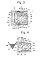
- a sealed vessel indicated at numeral ll,is formed to include protruding portions 12, 12 on its upper and lower surfaces at one end thereof.
- Leaf springs 13, 13 are attached at one end thereof to respective ones of the protruding portions 12, 12 by means of fixtures 14, 14, the leaf springs 13, 13 projecting forwardly from the protruding portions 12, 12 and extending in parallel.
- the free ends of the leaf springs 13, 13 are affixed to the arms of a substantially C-shaped supporting frame 15 by means of fixtures 16, 16, whereby the supporting frame 15 is supported by the leaf springs 13, 13.
- a rectangular load cell 17 Accommodated within the sealed vessel 11 is a rectangular load cell 17 whose mounting portion 17a is affixed to a side wall 11a of the vessel 11 in such a manner that the load cell is supported in cantilever fashion in parallel with the leaf springs 13, 13.
- An amplifier substrate 18 is attached at one end to the side wall 11a of the vessel at a point above the load cell 17 and extends in parallel therewith.
- the sealed vessel 11 is fixedly secured on the side of its protruding portions 12 to a frame 19 so as to be supported in cantilever fashion on the frame 19.
- the sealed vessel 11 further includes a lower wall 11b having an opening 11c of a prescribed size immediately below the load-receiving portion 17b of the load cell 17.
- a diaphragm 20 is affixed to the lower wall 11 of the sealed vessel 11 to close the opening 11c.
- a weighing hopper, not shown, is attached to the supporting frame 15 at a weighing point 21 which is in line with the free ends of the parallel leaf springs 13.
- the weighing portion 21 of the supporting frame is mechanically connected to the lower surface of the weight-receiving portion 17b of the load cell 7 at the free end thereof by means of wires 22a, 22b, wire 22a providing the connection between the diaphragm and weight-receiving portion, and wire 22b providing the connection between the diaphragm and the supporting frame.
- a liquid 23 comprising oil having a specific gravity greater than unity is sealed within the vessel 11.
- a plurality of holes 24, which ordinarily are closed by suitable means, are formed in the upper wall 11d of the sealed vessel 11. at a prescribed portion thereof for the purpose of changing the oil when required.
- Strain gauges are affixed to the upper and lower beams 17c, 17d at prescribed locations for delivering the electric signals corresponding to the load that will be applied to the weighing portion 21 of the load cell.
- the weighing portion 21 of the supporting frame 15 is subjected to a load, namely to the weight of articles disposed in the weighing hopper, not shown.
- the load causes vertical displacement of the supporting frame 15, which displacement is transmitted to the load-receiving portion 17b of the load cell 17 via the wires 22a, 22b and diaphragm 20.
- the load-receiving portion 17b of cell thus is displaced downwardly by an amount proportional to the load, thereby enabling the load to be detected.
- any water or foreign matter that might happen to penetrate the sealed vessel 11 will float on the surface of the liquid 23 owing to its specific gravity, which is greater than unity, and therefore will not contact the load cell 17. Any water or foreign matter found floating on the oil can be removed through the holes 24 by uncovering the holes as required.
- FIG. 4 Another embodiment of the present invention is shown in Fig. 4.
- the sealed vessel indicated at numeral 101, has an opening 101b of a prescribed size formed in the upper wall 101a thereof and is fixedly secured to a frame 102.
- the load cell 17 has its mounting portion 17a affixed to the side wall 101c of the vessel 101 so that the cell is supported in cantilever fashion within the vessel.
- the amplifier substrate 18 is also attached to the side wall 101c of the vessel 101.
- a diaphragm 103 is affixed to the upper wall 109 of the vessel 101 to close the opening 101b.
- the weighing portion 105 of a supporting frame 104 is mechanically connected to the upper beam 17c of the load cell 17 at the free end thereof by means of pressing members 106, 107 which sandwich the diaphragm 103 therebetween.
- the sealed vessel 101 contains a liquid comprising oil 23 of a specific gravity greater than unity.
- numeral 108 denotes a weighing hopper which is fixedly secured to a curved arm formed on the supporting frame 104.
- Numeral 109 denotes the articles which are to be weighed.
- the supporting frame 104 is displaced owing to the.load, or weight, of the articles loaded in the hopper 108.
- the displacement of the supporting frame 104 is transmitted to the free end of the load cell 17 via the pressing members 106, 107 and diaphragm 103, is detected by strain gauges, not shown, affixed to the load cell.
- the signals from the strain gauges provide an electrical indication of the weight of the articles 109.
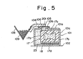
- Fig. 5 an embodiment using a cover-portion instead of the diaphram is disclosed, in which same parts as the embodiment of Fig. 4 are denoted by the.samee-. symbols.
- Numeral 201 denotes the cover-portion, through which the weighing portion 105 of the supporting frame 104 is mechanically connected to the upper beam 17c of the load cell 17.
- a liquid of a specific gravity greater than unity is sealed within vessel of prescribed dimensions
- a weight sensor such as a load cell is accommodated within the sealed vessel and immersed in the liquid
- a frame for supporting a weighing hopper or the like is mechanically connected to the sensor through a diaphragm which closes an opening formed in a portion of the sealed vessel.
- the liquid in which the sensor is immersed is oil or a similar substance
- elements such as strain gauges or the like will not develop deposits of chlorides and will not be oxidized by water droplets, moisture or harmful gases that may exist in the vicinity. This protects the strain gauges against deterioration and corrosion and attendant changes in electrical characteristics, thereby promoting a high degree of measuring accuracy.
Landscapes
- Physics & Mathematics (AREA)
- General Physics & Mathematics (AREA)
- Measurement Of Force In General (AREA)
Applications Claiming Priority (2)
| Application Number | Priority Date | Filing Date | Title |
|---|---|---|---|
| JP62474/81 | 1981-04-28 | ||
| JP1981062474U JPS57175020U (de) | 1981-04-28 | 1981-04-28 |
Publications (3)
| Publication Number | Publication Date |
|---|---|
| EP0063958A2 true EP0063958A2 (de) | 1982-11-03 |
| EP0063958A3 EP0063958A3 (en) | 1984-05-30 |
| EP0063958B1 EP0063958B1 (de) | 1987-07-15 |
Family
ID=13201217
Family Applications (1)
| Application Number | Title | Priority Date | Filing Date |
|---|---|---|---|
| EP82302166A Expired EP0063958B1 (de) | 1981-04-28 | 1982-04-27 | Wägevorrichtung |
Country Status (5)
| Country | Link |
|---|---|
| US (1) | US4441569A (de) |
| EP (1) | EP0063958B1 (de) |
| JP (1) | JPS57175020U (de) |
| AU (1) | AU539841B2 (de) |
| DE (1) | DE3276772D1 (de) |
Cited By (4)
| Publication number | Priority date | Publication date | Assignee | Title |
|---|---|---|---|---|
| FR2524636A1 (fr) * | 1982-04-01 | 1983-10-07 | Pfister Gmbh | Appareil pour la mesure d'une force |
| EP0126172A1 (de) * | 1983-05-20 | 1984-11-28 | Hottinger Baldwin Messtechnik Gmbh | Dämpfungsvorrichtung für Kraftaufnehmer |
| GB2159289A (en) * | 1984-05-25 | 1985-11-27 | Pitney Bowes Inc | Load cell having a flexure connector |
| EP0114530B1 (de) * | 1982-12-24 | 1987-10-14 | Shimadzu Corporation | Waage mit einer Kraftmesszelle |
Families Citing this family (8)
| Publication number | Priority date | Publication date | Assignee | Title |
|---|---|---|---|---|
| DE3619182A1 (de) * | 1986-06-06 | 1988-03-24 | Berkel Patent Nv | Vorrichtung zur bestimmung von gewichten einer last oder von kraeften |
| JPH0684901B2 (ja) * | 1987-08-01 | 1994-10-26 | 株式会社石田衡器製作所 | 組合せ計量装置 |
| US5327791A (en) * | 1992-01-16 | 1994-07-12 | Walker Robert R | Vehicle beam load measuring system |
| DE4220810C2 (de) * | 1992-06-25 | 1996-03-07 | Hottinger Messtechnik Baldwin | Kraftaufnehmer |
| US5386944A (en) * | 1994-02-17 | 1995-02-07 | Bunn-O-Matic Corporation | Weight controlled grinder and method of grinding coffee beans |
| US5880410A (en) * | 1995-01-26 | 1999-03-09 | Tedea Huntleigh International, Ltd. | Load cells with integral damping |
| US20030197094A1 (en) * | 2001-12-07 | 2003-10-23 | Daniel Preston | Load measuring device |
| DE10346697A1 (de) * | 2003-10-08 | 2005-05-12 | Garvens Automation Gmbh | Wiegeeinheit für eine Teilmengenwaage und Verfahren zu deren Herstellung |
Family Cites Families (10)
| Publication number | Priority date | Publication date | Assignee | Title |
|---|---|---|---|---|
| US1702741A (en) * | 1925-12-26 | 1929-02-19 | Mojonnier Bros Co | Weighing scale |
| US3180139A (en) * | 1960-10-12 | 1965-04-27 | Soderholm Arne | Force transducers |
| US3512595A (en) * | 1967-09-27 | 1970-05-19 | Blh Electronics | Suspension-type strain gage transducer structure |
| US3897681A (en) * | 1971-06-23 | 1975-08-05 | Mettler Instrumente Ag | Force measuring apparatus of the vibratory string type |
| US3905433A (en) * | 1972-01-24 | 1975-09-16 | Guinness Son & Co Ltd A | Weigh devices |
| DE2214418A1 (de) * | 1972-03-24 | 1973-10-11 | Hoefliger & Karg | Waegegeber |
| US4146100A (en) * | 1978-03-24 | 1979-03-27 | Revere Corporation Of America | Leverless scale sensor |
| AU515370B2 (en) * | 1977-08-01 | 1981-04-02 | Tokyo Electric Co. Ltd. | Integral beam strain gauge weigher |
| JPS54121169A (en) * | 1978-03-10 | 1979-09-20 | Matsushita Electric Ind Co Ltd | Load detector |
| ATE13723T1 (de) * | 1980-03-10 | 1985-06-15 | Wirth Gallo Patent Ag | Staub- und spritzwasserdichte waage. |
-
1981
- 1981-04-28 JP JP1981062474U patent/JPS57175020U/ja active Pending
-
1982
- 1982-04-27 DE DE8282302166T patent/DE3276772D1/de not_active Expired
- 1982-04-27 AU AU83026/82A patent/AU539841B2/en not_active Ceased
- 1982-04-27 EP EP82302166A patent/EP0063958B1/de not_active Expired
- 1982-04-28 US US06/372,706 patent/US4441569A/en not_active Expired - Fee Related
Cited By (4)
| Publication number | Priority date | Publication date | Assignee | Title |
|---|---|---|---|---|
| FR2524636A1 (fr) * | 1982-04-01 | 1983-10-07 | Pfister Gmbh | Appareil pour la mesure d'une force |
| EP0114530B1 (de) * | 1982-12-24 | 1987-10-14 | Shimadzu Corporation | Waage mit einer Kraftmesszelle |
| EP0126172A1 (de) * | 1983-05-20 | 1984-11-28 | Hottinger Baldwin Messtechnik Gmbh | Dämpfungsvorrichtung für Kraftaufnehmer |
| GB2159289A (en) * | 1984-05-25 | 1985-11-27 | Pitney Bowes Inc | Load cell having a flexure connector |
Also Published As
| Publication number | Publication date |
|---|---|
| EP0063958B1 (de) | 1987-07-15 |
| EP0063958A3 (en) | 1984-05-30 |
| US4441569A (en) | 1984-04-10 |
| DE3276772D1 (en) | 1987-08-20 |
| AU8302682A (en) | 1982-11-04 |
| AU539841B2 (en) | 1984-10-18 |
| JPS57175020U (de) | 1982-11-05 |
Similar Documents
| Publication | Publication Date | Title |
|---|---|---|
| US4441569A (en) | Weighing apparatus | |
| EP0634006B1 (de) | Wägezelle mit ausgespartem Biegestab in einer inneren Öffnung | |
| US3439761A (en) | Strain-gage transducer structures | |
| US4936399A (en) | Hand held weighing scale | |
| US4616511A (en) | Tactile sensor | |
| EP0519626A1 (de) | Piezoresistiver Beschleunigungsmesser mit zentraler Masse in einem Träger | |
| US3935914A (en) | Vehicle platform scale | |
| JPH02227615A (ja) | 流体レベルセンサー | |
| EP2189766A1 (de) | Messung der Rad- und/oder Achslast eines Straßenfahrzeugs | |
| RU2461802C2 (ru) | Способ мониторинга и/или определения состояния силоизмерительного устройства и силоизмерительное устройство | |
| JPH0653523A (ja) | 歪ゲージとこの種の歪ゲージを備えた測定量検出器 | |
| US5090493A (en) | Load cells and scales therefrom | |
| US3993150A (en) | Economical weighing apparatus employing a cantilever beam structure | |
| GB2216672A (en) | Electronic weighing machine | |
| EP0438413A4 (en) | Humidity control system for a scale | |
| EP0076315A1 (de) | Vorrichtung zur feststellung des zustandes einer flüssigkeit | |
| US4278139A (en) | Weighing apparatus with overload protection for off-center loading | |
| US4475409A (en) | Transducer for dynamometer | |
| US4107979A (en) | Method and device for measurement of environmental stress cracking | |
| USRE32003E (en) | Constant moment weigh scale with floating flexure beam | |
| US3381529A (en) | Static anemometer | |
| US4425808A (en) | Thin film strain transducer | |
| GB2190500A (en) | Liquid level sensor | |
| Karaus et al. | Load cells with small nominal load based on strain gauges using thin-film techniques | |
| US6360617B1 (en) | Load cell device for aircraft waste measurement |
Legal Events
| Date | Code | Title | Description |
|---|---|---|---|
| PUAI | Public reference made under article 153(3) epc to a published international application that has entered the european phase |
Free format text: ORIGINAL CODE: 0009012 |
|
| AK | Designated contracting states |
Designated state(s): DE FR GB IT |
|
| PUAL | Search report despatched |
Free format text: ORIGINAL CODE: 0009013 |
|
| AK | Designated contracting states |
Designated state(s): DE FR GB IT |
|
| 17P | Request for examination filed |
Effective date: 19841025 |
|
| 17Q | First examination report despatched |
Effective date: 19860314 |
|
| GRAA | (expected) grant |
Free format text: ORIGINAL CODE: 0009210 |
|
| AK | Designated contracting states |
Kind code of ref document: B1 Designated state(s): DE FR GB IT |
|
| ITF | It: translation for a ep patent filed | ||
| ET | Fr: translation filed | ||
| REF | Corresponds to: |
Ref document number: 3276772 Country of ref document: DE Date of ref document: 19870820 |
|
| PLBE | No opposition filed within time limit |
Free format text: ORIGINAL CODE: 0009261 |
|
| STAA | Information on the status of an ep patent application or granted ep patent |
Free format text: STATUS: NO OPPOSITION FILED WITHIN TIME LIMIT |
|
| 26N | No opposition filed | ||
| ITTA | It: last paid annual fee | ||
| PGFP | Annual fee paid to national office [announced via postgrant information from national office to epo] |
Ref country code: FR Payment date: 19950411 Year of fee payment: 14 |
|
| PGFP | Annual fee paid to national office [announced via postgrant information from national office to epo] |
Ref country code: GB Payment date: 19950418 Year of fee payment: 14 |
|
| PGFP | Annual fee paid to national office [announced via postgrant information from national office to epo] |
Ref country code: DE Payment date: 19950421 Year of fee payment: 14 |
|
| PG25 | Lapsed in a contracting state [announced via postgrant information from national office to epo] |
Ref country code: GB Effective date: 19960427 |
|
| GBPC | Gb: european patent ceased through non-payment of renewal fee |
Effective date: 19960427 |
|
| PG25 | Lapsed in a contracting state [announced via postgrant information from national office to epo] |
Ref country code: FR Effective date: 19961227 |
|
| PG25 | Lapsed in a contracting state [announced via postgrant information from national office to epo] |
Ref country code: DE Effective date: 19970101 |
|
| REG | Reference to a national code |
Ref country code: FR Ref legal event code: ST |