EP0063967A2 - Saddle balancing arrangement for machines - Google Patents
Saddle balancing arrangement for machines Download PDFInfo
- Publication number
- EP0063967A2 EP0063967A2 EP82400504A EP82400504A EP0063967A2 EP 0063967 A2 EP0063967 A2 EP 0063967A2 EP 82400504 A EP82400504 A EP 82400504A EP 82400504 A EP82400504 A EP 82400504A EP 0063967 A2 EP0063967 A2 EP 0063967A2
- Authority
- EP
- European Patent Office
- Prior art keywords
- carriage
- chain
- chains
- pulleys
- movements
- Prior art date
- Legal status (The legal status is an assumption and is not a legal conclusion. Google has not performed a legal analysis and makes no representation as to the accuracy of the status listed.)
- Granted
Links
Images


Classifications
-
- B—PERFORMING OPERATIONS; TRANSPORTING
- B23—MACHINE TOOLS; METAL-WORKING NOT OTHERWISE PROVIDED FOR
- B23Q—DETAILS, COMPONENTS, OR ACCESSORIES FOR MACHINE TOOLS, e.g. ARRANGEMENTS FOR COPYING OR CONTROLLING; MACHINE TOOLS IN GENERAL CHARACTERISED BY THE CONSTRUCTION OF PARTICULAR DETAILS OR COMPONENTS; COMBINATIONS OR ASSOCIATIONS OF METAL-WORKING MACHINES, NOT DIRECTED TO A PARTICULAR RESULT
- B23Q11/00—Accessories fitted to machine tools for keeping tools or parts of the machine in good working condition or for cooling work; Safety devices specially combined with or arranged in, or specially adapted for use in connection with, machine tools
- B23Q11/001—Arrangements compensating weight or flexion on parts of the machine
- B23Q11/0017—Arrangements compensating weight or flexion on parts of the machine compensating the weight of vertically moving elements, e.g. by balancing liftable machine parts
Definitions
- sliding members capable of moving with sliding guide, on a support which can itself be sliding as is the case, for example for a carriage sliding horizontally on a console itself sliding vertically.
- the present invention relates to a device for balancing an assembly formed by a first machine carriage supporting a second carriage movable on the first in a direction other than vertical, by means of a counterweight connected to the first carriage by chains, characterized in that this transmission comprises at least two chains connected to said first carriage by means of return pulleys driven by said chains and acting on a torsion shaft, the relative length of the chain strands connecting the pulleys to said first carriage being variable depending on the movement of the second carriage.
- the examples shown relate to the case of a machine tool comprising a console 1 (first carriage) sliding vertically on the slides 2 of a frame 3 and supporting a ram or the like 4 (second carriage) sliding horizontally on the console 1 by the slide 5.
- the invention is not limited to this example, nor to the case of horizontal sliding of the second carriage.
- the console 1 is connected to a counterweight 6 (weight P) by two chains or sets of chains 7 and 8.
- one of these chains in this case the chain 7 is connected directly to the console 1 by the clip 24, preferably adjustable in height, the chain 8 ending with a roller 9 which rolls on a ramp-10 linked to the ram 4.
- the transmission of the force exerted by the chain 8 to the console 1 is done either directly or by means of the roller (s) 11 rolling on the upper part of the ramp 10 and connected in 12 at console 1.
- the forces exerted by the counterweight 6 on the console 1 by the chains 7 and 8 are transmitted by the pulleys 13 and 14 which are driven by the chains 7 and 8 (the pulleys 22, 23 being simply return pulleys).
- the chains 7 and 8 will be roller chains and the pulleys 13 and 14 will have the shape of toothed pinions - any other arrangement within the reach of those skilled in the art to ensure the pulleys 13 and 14 are driven by chains 7 and 8 could be adopted.
- the pulleys 7 and 8 are integral with the torsion shaft 15.
- the ramp 10 is designed so that the displacements of the ram 4 cause a variation in the length of the strand of the chain 8a which separates the pulley 14 from the console 1 relative to the length of the strand of the chain 7a which separates the pulley 13 of console 1.
- the displacement of the ram 4 causes a displacement of the center of gravity of the assembly formed by the console 1 and the ram 4, which results in a torque exerted on the slide 2, and the ramp 10 will preferably be shaped so that that the difference in tension on the chains gives equal and opposite torque; in other words, the ramp 10 will be established so that the result of the forces exerted by the strands 7a and 8a remains constantly in the vertical plane containing the center of gravity of the ram + console assembly, and perpendicular to the guide plane of the ram 4.
- the counterweight 6 is suspended from the chains 7 and 8 by the lifter 16 connected to the counterweight 6 by the articulation 28; it follows that the variations in relative length of the chains have no effect on the lateral position of the center of gravity of the counterweight 6.
- the support pieces 17, 18 are columns which pass through the frame 3 of the machine without mechanical connection, through simple guides 25, 26 and return the forces to the base 19 of the machine or to the foundation.
- the end of the chain 8 can be connected to the console 1 via a rack with a rotating arm or a cam whose rotation is controlled by the ram movement control member. 4.
- this end can carry a screw coagulating with a nut driven in rotation by said member for controlling the movements of the ram 4, or directly by the latter, during its movements.
- the chain 8 carries at its end a screw 101 engaging in a nut 102 (for example a ball nut) integral with a pulley 103.
- the nut and the pulley are trapped in a yoke 104 linked to the console,
- a cable or a ribbon 105 is wound on one side on the pulley 103 and is attached on the other to the support 106 linked to the ram 4.
- the columns 17 and 18 support a frame 27 carrying the bearings of the pulleys 13 and 14 the torsion shaft 15 and the return pulleys 22, 23.
- This frame 27 is connected to the frame 3 by an attachment point 28 which is not a rigid attachment and only complements guides 25 and 26.
Landscapes
- Engineering & Computer Science (AREA)
- Mechanical Engineering (AREA)
- Testing Of Balance (AREA)
- Transmission Devices (AREA)
- Drilling And Boring (AREA)
- Replacement Of Web Rolls (AREA)
- Supply And Distribution Of Alternating Current (AREA)
- Devices For Conveying Motion By Means Of Endless Flexible Members (AREA)
- Character Spaces And Line Spaces In Printers (AREA)
Abstract
Dispositif d'équilibrage d'un ensemble formé par un premier chariot de machine (1) supportant un second chariot mobile (4) sur le premier selon une direction autre que verticale, par le moyen d'un contrepoids (6) relié au premier chariot (1) par des chaînes (7, 8). Cette transmission comprend au moins deux chaînes (7, et 8) reliées audit premier chariot (1) par l'intermédiaire de poulies de renvoi (13,14) entraînées par lesdites chaînes (7 et 8) et agissant sur un arbre de torsion (15), la longueur relative des brins de chaîne (7a, 8a) reliant les poulies (13, 14) audit premier chariot (1) étant variable en fonction du déplacement du second chariot (4).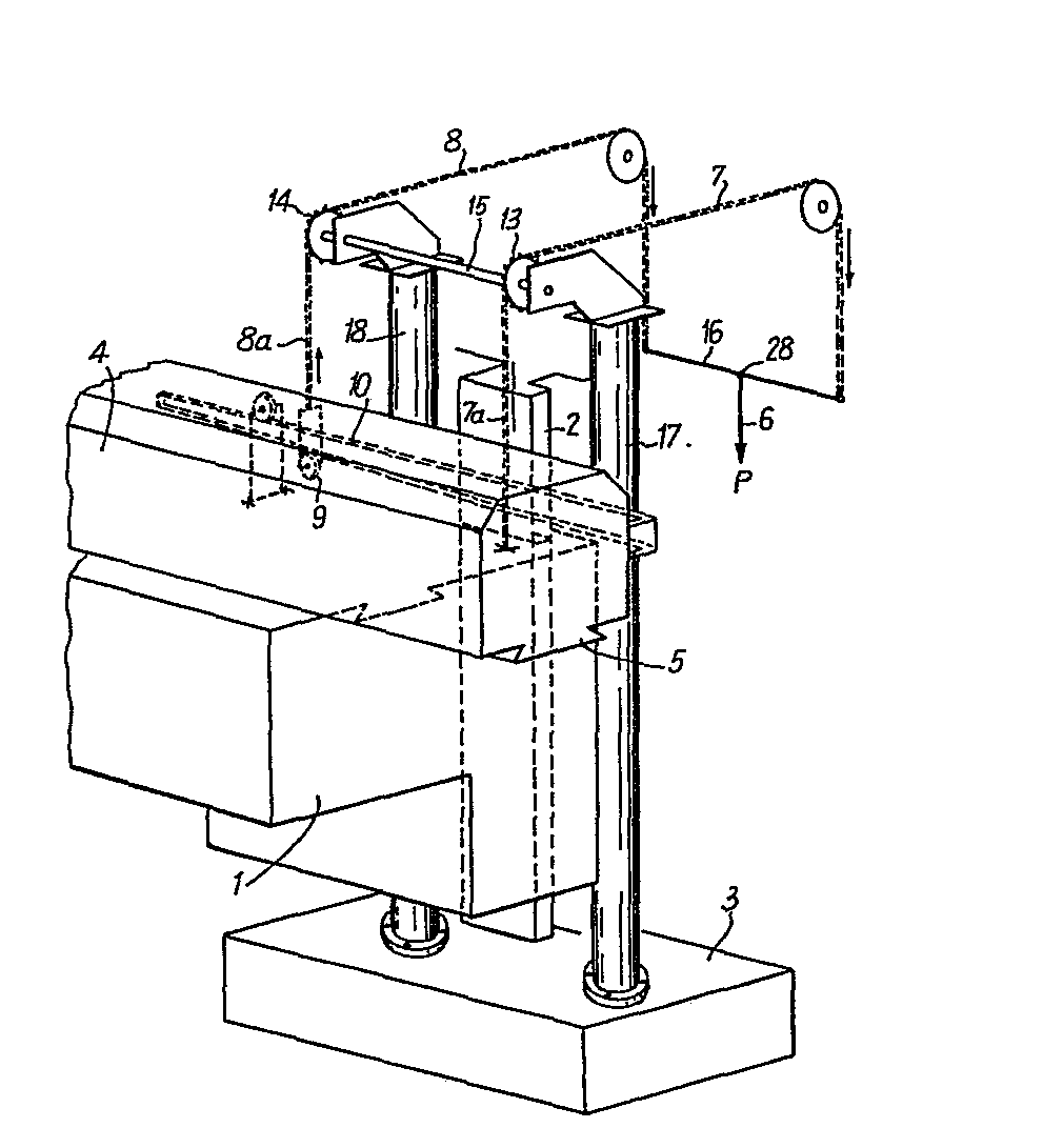
Description
Dans de nombreuses machines, notamment les machines outils, il existe un ou plusieurs organes coulissants, susceptibles de se déplacer avec un guidage par glissière, sur un support qui peut lui-même être coulissant comme c'est le cas, par exemple pour un chariot coulissant horizontalement sur une console elle-même coulissant verticalement.In many machines, in particular machine tools, there are one or more sliding members, capable of moving with sliding guide, on a support which can itself be sliding as is the case, for example for a carriage sliding horizontally on a console itself sliding vertically.
Il est connu de diminuer ou d'annuler l'action de la pesanteur sur le dispositif de mise en position d'un tel organe par contrepoids, vérin, ressort, etc.It is known to reduce or cancel the action of gravity on the device for positioning such a member by counterweight, jack, spring, etc.
Les actions des forces exercées par ces moyens sur l'ensemble à équilibrer admettent une résultante dont le point d'application est généralement fixe.The actions of the forces exerted by these means on the assembly to be balanced admit a result whose application point is generally fixed.
Dans le cas de machines comportant un chariot supportant un deuxième chariot, mobile sur le premier selon une direction quelconque autre que verticale, le centre de gravité de l'ensemble se déplace ; il en résulte une distance variable entre le point d'application de la résultante des forces d'équilibrage et le centre de gravité de l'ensemble des chariots qui crée un couple de forces dont le moment provoque la déformation des guidages, le déplacement incontrôlé des chariots dans le jeu de fonctionnement de leurs glissières ainsi que des efforts antagonistes dans le dispositif de mise en position.In the case of machines comprising a carriage supporting a second carriage, movable on the first in any direction other than vertical, the center of gravity of the assembly moves; this results in a variable distance between the point of application of the result of the balancing forces and the center of gravity of the set of carriages which creates a couple of forces whose moment causes the deformation of the guides, the uncontrolled movement of the carriages in the operating clearance of their slides as well as opposing forces in the positioning device.
Différentes solutions ont déjà été proposées pour remédier à ce problème dont l'acuité est accrue par le développement des machines à commande numérique. En effet, sur de telles machines, la mise en place des organes est automatique et il faut donc éviter ou corriger automatiquement les déformations, déplacements incontrôlés, ou jeux, qui, auparavant, pouvaient être corrigés par un réglage manuel.Various solutions have already been proposed to remedy this problem, the acuity of which is increased by the development of numerically controlled machines. Indeed, on such machines, the positioning of the members is automatic and it is therefore necessary to automatically avoid or correct deformations, uncontrolled displacements, or clearances, which previously could be corrected by manual adjustment.
Selon l'une de ces solutions, décrite au brevet français n° 72.32413 (n° de publication 2.153.990), on emploie un contrepoids dont la position du centre de gravité peut être modifiée par raccourcissement ou allongement de l'une de ses chaînes de suspension, lesquelles supportent ce contrepoids en des points distincts et distants,According to one of these solutions, described in French patent n ° 72.32413 (publication n ° 2.153.990), a counterweight is used, the position of the center of gravity of which can be modified by shortening or lengthening one of its chains of suspension, which support this counterweight at distinct and distant points,
Cependant, les modifications ainsi obtenues sont de faible amplitude-et ne peuvent être valablement utilisées que si l'organe mobile selon une direction horizontale est d'un poids restreint, de telle sorte que le déplacement du centre de gravité soit peu important,However, the modifications thus obtained are of small amplitude and can only be validly used if the moving member in a horizontal direction is of a limited weight, so that the displacement of the center of gravity is not significant,
La présente invention a pour objet un dispositif d'équilibrage d'un ensemble formé par un premier chariot de machine supportant un second chariot mobile sur le premier selon une direction autre que verticale, par le moyen d'un contrepoids relié au premier chariot par des chaînes, caractérisé en ce que cette transmission comprend au moins deux chaînes reliées audit premier chariot par l'intermédiaire de poulies de renvoi entraînéespar lesdites chaînes et agissant sur un arbre de torsion, la longueur relative des brins de chaîne reliant les poulies audit premier chariot étant variable en fonction du déplacement du second chariot.The present invention relates to a device for balancing an assembly formed by a first machine carriage supporting a second carriage movable on the first in a direction other than vertical, by means of a counterweight connected to the first carriage by chains, characterized in that this transmission comprises at least two chains connected to said first carriage by means of return pulleys driven by said chains and acting on a torsion shaft, the relative length of the chain strands connecting the pulleys to said first carriage being variable depending on the movement of the second carriage.
Par ce moyen, à l'effort appliqué par le contrepoids sur chacune des attaches reliant les chaînes au premier chariot vient s'ajouter un moment de torsion faisant varier l'intensité relative de ces efforts selon la fonction adoptée et par conséquent de nature à compenser le couple résultat du déplacement du centre de gravité du second chariot,By this means, to the force applied by the counterweight on each of the fasteners connecting the chains to the first carriage is added a torsional moment varying the relative intensity of these forces according to the function adopted and therefore likely to compensate the couple result of displacement of the center of gravity of the second carriage,
L'invention vise également les dispositions ci-après :
- a) La variation de longueur relative des brins de chaîne est fonction linéaire du déplacement du second chariot.
- b) La variation de longueur relative des brins de chaîne reliant les poulies au premier chariot est obtenue par au moins un organe mobile dont le mouvement est commandé par les déplacements du second chariot, ledit mouvement faisant varier la distance au premier chariot de l'extrémité de la chaîne correspondante.
- c) Ledit organe est une rampe solidaire du second chariot et sur laquelle roule un galet lié à l'extrémité d'une chaîne, l'effort appliqué par cette chaîne étant transmis au premier chariot par l'intermédiaire du second.
- d) Ledit organe est une pièce mécanique mobile portée par le premier chariot dont les déplacements sont commandés par l'organe commandant les déplacements du second chariot et sur laquelle est fixée l'extrémité d'une chaîne.
- e) La variation de longueur relative des brins de chaîne est obtenue par au moins un écrou, porté par le premier chariot, mis en mouvement par les déplacements du second chariot ou par l'organe commandant ces déplacements et agissant sur une vis portée par l'extrémité d'une chaîne.
- f) Le contrepoids est porté par les chaînes par l'intermédiaire d'un palonnier relié avec articulation en un seul point du contrepoids.
- a) The variation in relative length of the chain strands is a linear function of the movement of the second carriage.
- b) The variation in relative length of the chain strands connecting the pulleys to the first carriage is obtained by at least one movable member whose movement is controlled by the movements of the second carriage, said movement varying the distance to the first carriage from the end of the corresponding string.
- c) Said member is a ramp integral with the second carriage and on which rolls a roller linked to the end of a chain, the force applied by this chain being transmitted to the first carriage via the second.
- d) Said member is a movable mechanical part carried by the first carriage whose movements are controlled by the member controlling the movements of the second carriage and on which the end of a chain is fixed.
- e) The variation in relative length of the chain strands is obtained by at least one nut, carried by the first carriage, set in motion by the movements of the second carriage or by the member controlling these movements and acting on a screw carried by the end of a chain.
- f) The counterweight is carried by the chains by means of a lifting beam connected with articulation at a single point of the counterweight.
Cette disposition a pour but que les variations de longueur de chaîne n'entraînent pas de déplacements latéraux du contrepoids.The purpose of this arrangement is that variations in chain length do not cause lateral movements of the counterweight.
g) L'équipage portant les poulies et l'arbre de torsion est dépourvu de liaison mécanique rigide avec les chariots et leur bâti support.g) The crew carrying the pulleys and the torsion shaft has no rigid mechanical connection with the carriages and their support frame.
h) L'équipage portant les poulies et l'arbre de torsion repose sur des pièces d'appui telles que des colonnes transmettant les efforts sur le socle ou la fondation, sur lequel est fixé le bâti de la machine sans liaison mécanique avec les chariots et le bâti.h) The crew carrying the pulleys and the torsion shaft rests on support parts such as columns transmitting the forces on the base or the foundation, on which is fixed the frame of the machine without mechanical connection with the carriages and the frame.
i) La variation de longueur relative des brins de chaîne est établie de telle sorte que la résultante des forces d'équilibrage reste en permanence contenue dans un plan vertical contenant le centre de gravité de l'ensemble des chariots et perpendiculaire au plan de guidage du second chariot.i) The variation in relative length of the chain strands is established so that the result of the balancing forces remains permanently contained in a vertical plane containing the center of gravity of all of the carriages and perpendicular to the guide plane of the second cart.
L'invention est décrite plus amplement avec référence au dessin annexé sur lequel :
- La figure est une vue schématique perspective montrant le principe de l'invention ;
- La figure 2 est une vue de côté d'un exemple de réalisation ;
- La figure 3 est une vue de face de la machine de la figure 2 ;
- La figure 4 est une vue de dessus de la machine de la figure 2 ;
- La figure 5 est une vue schématique latérale partielle d'une variante de réalisation de la figure 2 ;
- La figure 6 est une vue schématique partielle de dessus de la même variante.
- The figure is a schematic perspective view showing the principle of the invention;
- Figure 2 is a side view of an exemplary embodiment;
- Figure 3 is a front view of the machine of Figure 2;
- Figure 4 is a top view of the machine of Figure 2;
- Figure 5 is a partial schematic side view of an alternative embodiment of Figure 2;
- Figure 6 is a partial schematic view from above of the same variant.
Les exemples représentés se rapportent au cas d'une machine outil comportant une console 1 (premier chariot) coulissant verticalement sur les glissières 2 d'un bâti 3 et supportent un bélier ou analogue 4 (second chariot) coulissant horizontalement sur la console 1 par la glissière 5.The examples shown relate to the case of a machine tool comprising a console 1 (first carriage) sliding vertically on the
Mais l'invention n'est pas limitée à cet exemple, ni au cas de coulissement horizontal du second chariot.However, the invention is not limited to this example, nor to the case of horizontal sliding of the second carriage.
Conformément à l'invention, la console 1 est reliée à un contrepoids 6 (poids P) par deux chaînes ou ensembles de chaînes 7 et 8.According to the invention, the console 1 is connected to a counterweight 6 (weight P) by two chains or sets of
Dans l'exemple représenté, l'une de ces chaînes, en l'espèce la chaîne 7 est reliée directement à la console 1 par l'attache 24, de préférence réglable en hauteur, la chaîne 8 se terminant par un galet 9 qui roule sur une rampe-10 liée au bélier 4. La transmission de l'effort exercé par la chaîne 8 à la console 1 se fait soit directement soit par l'intermédiaire du ou des galets 11 roulant sur la partie supérieure de la rampe 10 et relié en 12 à la console 1.In the example shown, one of these chains, in this case the chain 7 is connected directly to the console 1 by the
La transmission des efforts exercés par le contrepoids 6 sur la console 1 par les chaînes 7 et 8 est effectuée par les poulies 13 et 14 qui sont entraînées par les chaînes 7 et 8 (les poulies 22, 23 étant simplement des poulies de renvoi). Par exemple les chaînes 7 et 8 seront des chaînes à galets et les poulies 13 et 14 auront la forme de pignons dentés -toute autre disposition à la portée de l'homme de l'art pour assurer l'entraînement des poulies 13 et 14 par les chaînes 7 et 8 pourra être adoptée.The forces exerted by the
Les poulies 7 et 8 sont solidaires de l'arbre de torsion 15.The
La rampe 10 est dessinée de façon à ce que les déplacements du bélier 4 provoquent une variation de longueur du brin de la chaîne 8a qui sépare la poulie 14 de la console 1 par rapport à la longueur du brin de la chaîne 7a qui sépare la poulie 13 de la console 1.The
Cette variation relative provoque une torsion de l'arbre 15 qui se traduit par un moment M donnant sur le diamètre extérieur des poulies 13 et 14 un effort tangentiel T. Ainsi, si P est le poids du contrepoids 6, les efforts appliqués sur la console 1 par les brins de chaîne 7 et 8 auront pour valeurs respectives :
Le déplacement du bélier 4 provoque un déplacement du centre de gravité de l'ensemble formé par la console 1 et le bélier 4, qui se traduit en un couple exercé sur la glissière 2, et la rampe 10 sera de préférence conformée de façon à ce que la différence de tension sur les chaînes donne un couple égal et de sens inverse ; en d'autres termes, la rampe 10 sera établie pour que la résultante des efforts exercés par les brins 7a et 8a reste constamment dans le plan vertical contenant le centre de gravité de l'ensemble bélier + console, et perpendiculaire au plan de guidage du bélier 4.The displacement of the
Conformément à une disposition de l'invention, le contrepoids 6 est suspendu aux chaînes 7 et 8 par le palonnier 16 relié au contrepoids 6 par l'articulation 28 ; il en résulte que les variations de longueur relative des chaînes n'ont pas d'effet sur la position latérale du centre de gravité du contrepoids 6.In accordance with an arrangement of the invention, the
Dans l'exemple représenté les pièces d'appui 17, 18 sont des colonnes qui traversent le bâti 3 de la machine sans liaison mécanique, à travers de simples guidages 25, 26 et renvoient les efforts sur le socle 19 de la machine ou sur la fondation.In the example shown the
En variante de la rampe 10, on peut utiliser d'autres moyens de variations de la longueur relative des brins des chaînes 7 et 8 séparant les poulies 13 et 14 de la console 1.As an alternative to the
Par exemple, l'extrémité de la chaîne 8 peut être reliée à la console 1 par l'intermédiaire d'une crémaillère d'un bras tournant ou d'une came dont la rotation est commandée par l'organe de commande des déplacements du bélier 4.For example, the end of the
Ou encore, cette extrémité peut porter une vis coagissant avec un écrou entraîné en rotation par ledit organe de commande des déplacements du bélier 4, ou directement par ce dernier, au cours de ses déplacements.Or, this end can carry a screw coagulating with a nut driven in rotation by said member for controlling the movements of the
Cette dernière variante est représentée schématiquement sur les figures 5 et 6.This latter variant is shown diagrammatically in FIGS. 5 and 6.
La chaîne 8 porte à son extrémité une vis 101 s'engageant dans un écrou 102 (par exemple un écrou à billes) solidaires d'une poulie 103. L'écrou et la poulie sont emprisonnés dans une chape 104 liée à la console, Un câble ou un ruban 105 s'enroule d'un côté sur la poulie 103 et est attaché de l'autre au support 106 lié au bélier 4.The
Lorsque le bélier 4 se déplace, il entraîne le câble 106 qui fait tourner la poulie 103 donc l'écrou 102, ce qui provoque le mouvement axial de la vis 101, et une variation de longueur de la chaîne 8. L'ensemble vis-écrou à billes étant parfaitement réversible, la traction sur la chaîne 8 se traduit par un couple sur la poulie 102, ce qui assure une tension permanente sur le ruban ou câble 105.When the
Dans l'exemple des figures 2, 3 et 4 les colonnes 17 et 18 supportent un châssis 27 portant les paliers des poulies 13 et 14 l'arbre de torsion 15 et les poulies de renvoi 22, 23. Ce châssis 27 est relié au bâti 3 par un point d'attache 28 qui n'est pas une attache rigide et vient seulement compléter les guidages 25 et 26.In the example of FIGS. 2, 3 and 4 the
L'invention n'est pas limitée à l'exemple décrit mais peut être réalisée de façons diverses selon les caractéristiques propres des machines auxquelles elle est appliquée,The invention is not limited to the example described but can be carried out in various ways depending on the specific characteristics of the machines to which it is applied,
Claims (10)
Priority Applications (1)
| Application Number | Priority Date | Filing Date | Title |
|---|---|---|---|
| AT82400504T ATE23814T1 (en) | 1981-04-17 | 1982-03-19 | DEVICE FOR BALANCING A MOVABLE MACHINE SLIDE. |
Applications Claiming Priority (2)
| Application Number | Priority Date | Filing Date | Title |
|---|---|---|---|
| FR8107794 | 1981-04-17 | ||
| FR8107794A FR2504046A1 (en) | 1981-04-17 | 1981-04-17 | DEVICE FOR BALANCING MOBILE TROLLEY OF MACHINES |
Publications (3)
| Publication Number | Publication Date |
|---|---|
| EP0063967A2 true EP0063967A2 (en) | 1982-11-03 |
| EP0063967A3 EP0063967A3 (en) | 1984-12-27 |
| EP0063967B1 EP0063967B1 (en) | 1986-11-26 |
Family
ID=9257551
Family Applications (1)
| Application Number | Title | Priority Date | Filing Date |
|---|---|---|---|
| EP82400504A Expired EP0063967B1 (en) | 1981-04-17 | 1982-03-19 | Saddle balancing arrangement for machines |
Country Status (7)
| Country | Link |
|---|---|
| US (1) | US4470572A (en) |
| EP (1) | EP0063967B1 (en) |
| JP (1) | JPS5874933A (en) |
| AT (1) | ATE23814T1 (en) |
| DE (1) | DE3274431D1 (en) |
| ES (1) | ES510912A0 (en) |
| FR (1) | FR2504046A1 (en) |
Cited By (2)
| Publication number | Priority date | Publication date | Assignee | Title |
|---|---|---|---|---|
| EP0113389A1 (en) * | 1982-12-10 | 1984-07-18 | MDC Max Dätwyler Bleienbach AG | Device for relieving the guideway for parts substantially movable in a vertical direction, particularly of machine tool parts |
| CN109681579B (en) * | 2019-01-14 | 2020-07-28 | 上海交大临港智能制造创新科技有限公司 | Counterweight mechanism |
Families Citing this family (6)
| Publication number | Priority date | Publication date | Assignee | Title |
|---|---|---|---|---|
| CN100408235C (en) * | 2006-10-13 | 2008-08-06 | 赵联 | Vertical numerical controlled lathe Z shaft counterweight mechanism |
| CN102126137A (en) * | 2011-03-25 | 2011-07-20 | 林淑芬 | Gantry machine tool structure |
| CN102837195A (en) * | 2011-09-19 | 2012-12-26 | 湖北汇科数控组合机电装备有限公司 | Vertical slide platform |
| CN103991000B (en) * | 2014-01-20 | 2016-06-22 | 宁波川田精密机械有限公司 | One gantry pommel horse seat supports mechanism |
| CN105499649B (en) * | 2015-10-28 | 2017-09-12 | 镇江裕久智能装备股份有限公司 | A kind of drilling machine custombuilt power unit answering system |
| US20250073912A1 (en) * | 2023-09-02 | 2025-03-06 | Khalifa University of Science and Technology | Multi-stage hole machining end-effector for cobot systems |
Family Cites Families (8)
| Publication number | Priority date | Publication date | Assignee | Title |
|---|---|---|---|---|
| US1669915A (en) * | 1922-12-02 | 1928-05-15 | Pratt & Whitney Co | Counterbalancing means for multiple drills |
| GB1239421A (en) * | 1968-06-25 | 1971-07-14 | ||
| DE2147985A1 (en) * | 1971-09-25 | 1973-03-29 | Scharmann & Co | HORIZONTAL DRILLING AND MILLING MILL WITH A SPINDLE CASE MOVED UP AND DOWN ON GUIDES |
| DE2328404A1 (en) * | 1973-06-04 | 1974-12-19 | Schiess Ag | STAND SLIDE OF A MACHINE TOOL |
| US4019442A (en) * | 1975-03-06 | 1977-04-26 | Roll-O-Matic Chain Company | Bulkhead assembly and counterbalance mechanism therefor |
| US4043529A (en) * | 1976-10-20 | 1977-08-23 | Ferro Manufacturing Corporation | Seat adjusting mechanism |
| CS201349B1 (en) * | 1978-10-09 | 1980-10-31 | Vaclav Smrha | Facility for decreasing the deformation of the stands and frames of machines |
| US4277044A (en) * | 1979-09-07 | 1981-07-07 | American Optical Corporation | Mechanical counterbalance |
-
1981
- 1981-04-17 FR FR8107794A patent/FR2504046A1/en active Granted
-
1982
- 1982-03-19 AT AT82400504T patent/ATE23814T1/en not_active IP Right Cessation
- 1982-03-19 EP EP82400504A patent/EP0063967B1/en not_active Expired
- 1982-03-19 DE DE8282400504T patent/DE3274431D1/en not_active Expired
- 1982-03-23 US US06/361,060 patent/US4470572A/en not_active Expired - Lifetime
- 1982-03-29 ES ES510912A patent/ES510912A0/en active Granted
- 1982-04-07 JP JP57056812A patent/JPS5874933A/en active Granted
Cited By (2)
| Publication number | Priority date | Publication date | Assignee | Title |
|---|---|---|---|---|
| EP0113389A1 (en) * | 1982-12-10 | 1984-07-18 | MDC Max Dätwyler Bleienbach AG | Device for relieving the guideway for parts substantially movable in a vertical direction, particularly of machine tool parts |
| CN109681579B (en) * | 2019-01-14 | 2020-07-28 | 上海交大临港智能制造创新科技有限公司 | Counterweight mechanism |
Also Published As
| Publication number | Publication date |
|---|---|
| JPS5874933A (en) | 1983-05-06 |
| DE3274431D1 (en) | 1987-01-15 |
| ES8302513A1 (en) | 1983-02-01 |
| JPS6252173B2 (en) | 1987-11-04 |
| FR2504046A1 (en) | 1982-10-22 |
| EP0063967A3 (en) | 1984-12-27 |
| EP0063967B1 (en) | 1986-11-26 |
| US4470572A (en) | 1984-09-11 |
| ES510912A0 (en) | 1983-02-01 |
| ATE23814T1 (en) | 1986-12-15 |
| FR2504046B1 (en) | 1984-09-28 |
Similar Documents
| Publication | Publication Date | Title |
|---|---|---|
| FR2472426A1 (en) | ||
| EP0063967B1 (en) | Saddle balancing arrangement for machines | |
| FR2535244A1 (en) | PRESS TO PUNCH | |
| FR2545456A1 (en) | CARRIER OF WORKPIECES OR WORK HOLDERS, ESPECIALLY FOR MOUNTING MACHINE | |
| FR2596319A1 (en) | BENDING APPARATUS FOR BENDER | |
| FR2719794A1 (en) | Wire transfer apparatus. | |
| FR2835034A1 (en) | EFFORTS DISCHARGE DEVICE FOR CABLE CARRIER CHAINS | |
| FR2532924A1 (en) | DRIVE SYSTEM FOR METAL CABLE LIFT APPARATUSES | |
| EP0542610B1 (en) | Workpiece-supporting device for a bending machine | |
| EP0070221B1 (en) | Pressure dividing apparatus for a machine tool carriage on its track | |
| FR2498093A1 (en) | Wire coiler with stretch and coiling units - has drive shafts with spring rollers and wire grooves for straight fast movement avoiding plastic deformation in coiling | |
| FR2593729A1 (en) | PLATE PROCESSING MACHINE, ESPECIALLY PUNCHING MACHINE | |
| EP0015215B1 (en) | Workpiece loader or extractor | |
| FR2550773A1 (en) | METHOD AND DEVICE FOR SEPARATING GROUPS OF DISK-SHAPED OBJECTS FROM A CELL ARRIVING IN A CURRENT | |
| EP1319922B1 (en) | Column for measuring longitudinal dimensions | |
| EP0469212A1 (en) | Device for vertically moving a bed in a supporting structure | |
| EP0053062B1 (en) | Apparatus for balancing a headstock movable on an arm supported by a single column | |
| FR2604138A1 (en) | Device for holding overhead cables driven in advancement in line at a pylon, and overhead cable transportation installation comprising such a device | |
| FR2767707A1 (en) | WEIGHT MACHINE | |
| CH361393A (en) | Debarking device for logs or logs | |
| EP0708319A1 (en) | Device for measuring tension load on a winch cable | |
| CH617407A5 (en) | Device for regulating the pay-out tension of a flexible body wound on a support | |
| EP1364904A1 (en) | Device for moving an elevator car | |
| FR2542251A1 (en) | Crawler link extraction device | |
| CH333112A (en) | Vibrator roller |
Legal Events
| Date | Code | Title | Description |
|---|---|---|---|
| PUAI | Public reference made under article 153(3) epc to a published international application that has entered the european phase |
Free format text: ORIGINAL CODE: 0009012 |
|
| AK | Designated contracting states |
Designated state(s): AT BE CH DE GB IT LU NL SE |
|
| 17P | Request for examination filed |
Effective date: 19830124 |
|
| PUAL | Search report despatched |
Free format text: ORIGINAL CODE: 0009013 |
|
| AK | Designated contracting states |
Designated state(s): AT BE CH DE GB IT LI LU NL SE |
|
| GRAA | (expected) grant |
Free format text: ORIGINAL CODE: 0009210 |
|
| AK | Designated contracting states |
Kind code of ref document: B1 Designated state(s): AT BE CH DE GB IT LI LU NL SE |
|
| PG25 | Lapsed in a contracting state [announced via postgrant information from national office to epo] |
Ref country code: NL Effective date: 19861126 Ref country code: AT Effective date: 19861126 |
|
| REF | Corresponds to: |
Ref document number: 23814 Country of ref document: AT Date of ref document: 19861215 Kind code of ref document: T |
|
| PG25 | Lapsed in a contracting state [announced via postgrant information from national office to epo] |
Ref country code: SE Effective date: 19861130 |
|
| REF | Corresponds to: |
Ref document number: 3274431 Country of ref document: DE Date of ref document: 19870115 |
|
| ITF | It: translation for a ep patent filed | ||
| PG25 | Lapsed in a contracting state [announced via postgrant information from national office to epo] |
Ref country code: LU Free format text: LAPSE BECAUSE OF NON-PAYMENT OF DUE FEES Effective date: 19870331 |
|
| NLV1 | Nl: lapsed or annulled due to failure to fulfill the requirements of art. 29p and 29m of the patents act | ||
| PLBE | No opposition filed within time limit |
Free format text: ORIGINAL CODE: 0009261 |
|
| STAA | Information on the status of an ep patent application or granted ep patent |
Free format text: STATUS: NO OPPOSITION FILED WITHIN TIME LIMIT |
|
| BERE | Be: lapsed |
Owner name: CENTRE D'ETUDES DU FRAISAGE (C.E.F.) Effective date: 19870331 |
|
| 26N | No opposition filed | ||
| PG25 | Lapsed in a contracting state [announced via postgrant information from national office to epo] |
Ref country code: BE Effective date: 19890331 |
|
| ITTA | It: last paid annual fee | ||
| PGFP | Annual fee paid to national office [announced via postgrant information from national office to epo] |
Ref country code: GB Payment date: 19980313 Year of fee payment: 17 |
|
| PGFP | Annual fee paid to national office [announced via postgrant information from national office to epo] |
Ref country code: DE Payment date: 19980319 Year of fee payment: 17 |
|
| PGFP | Annual fee paid to national office [announced via postgrant information from national office to epo] |
Ref country code: CH Payment date: 19980324 Year of fee payment: 17 |
|
| PG25 | Lapsed in a contracting state [announced via postgrant information from national office to epo] |
Ref country code: GB Free format text: LAPSE BECAUSE OF NON-PAYMENT OF DUE FEES Effective date: 19990319 |
|
| PG25 | Lapsed in a contracting state [announced via postgrant information from national office to epo] |
Ref country code: LI Free format text: LAPSE BECAUSE OF NON-PAYMENT OF DUE FEES Effective date: 19990331 Ref country code: CH Free format text: LAPSE BECAUSE OF NON-PAYMENT OF DUE FEES Effective date: 19990331 |
|
| GBPC | Gb: european patent ceased through non-payment of renewal fee |
Effective date: 19990319 |
|
| REG | Reference to a national code |
Ref country code: CH Ref legal event code: PL |
|
| PG25 | Lapsed in a contracting state [announced via postgrant information from national office to epo] |
Ref country code: DE Free format text: LAPSE BECAUSE OF NON-PAYMENT OF DUE FEES Effective date: 20000101 |