EP0063981A1 - Verfahren zur Herstellung von dünnen Elektroden, insbesondere Gaselektroden, für elektrochemische Anlagen und durch dieses Verfahren erhaltene dünne Elektroden, wobei die Elektroden mit Stromkollektoren versehen sein können - Google Patents
Verfahren zur Herstellung von dünnen Elektroden, insbesondere Gaselektroden, für elektrochemische Anlagen und durch dieses Verfahren erhaltene dünne Elektroden, wobei die Elektroden mit Stromkollektoren versehen sein können Download PDFInfo
- Publication number
- EP0063981A1 EP0063981A1 EP82400638A EP82400638A EP0063981A1 EP 0063981 A1 EP0063981 A1 EP 0063981A1 EP 82400638 A EP82400638 A EP 82400638A EP 82400638 A EP82400638 A EP 82400638A EP 0063981 A1 EP0063981 A1 EP 0063981A1
- Authority
- EP
- European Patent Office
- Prior art keywords
- electrode
- mixture
- lubricant
- electrodes
- particles
- Prior art date
- Legal status (The legal status is an assumption and is not a legal conclusion. Google has not performed a legal analysis and makes no representation as to the accuracy of the status listed.)
- Granted
Links
- 238000000034 method Methods 0.000 title claims abstract description 44
- 238000004519 manufacturing process Methods 0.000 title claims abstract description 11
- 239000000203 mixture Substances 0.000 claims abstract description 41
- 239000004810 polytetrafluoroethylene Substances 0.000 claims abstract description 37
- 229920001343 polytetrafluoroethylene Polymers 0.000 claims abstract description 37
- PXHVJJICTQNCMI-UHFFFAOYSA-N Nickel Chemical compound [Ni] PXHVJJICTQNCMI-UHFFFAOYSA-N 0.000 claims abstract description 30
- 239000000314 lubricant Substances 0.000 claims abstract description 27
- -1 polytetrafluoroethylene Polymers 0.000 claims abstract description 20
- 239000002245 particle Substances 0.000 claims abstract description 19
- 150000001875 compounds Chemical class 0.000 claims abstract description 18
- 229910052759 nickel Inorganic materials 0.000 claims abstract description 15
- 239000000835 fiber Substances 0.000 claims abstract description 14
- 239000004094 surface-active agent Substances 0.000 claims abstract description 7
- 239000008240 homogeneous mixture Substances 0.000 claims abstract description 6
- 230000001464 adherent effect Effects 0.000 claims abstract description 5
- RYGMFSIKBFXOCR-UHFFFAOYSA-N Copper Chemical compound [Cu] RYGMFSIKBFXOCR-UHFFFAOYSA-N 0.000 claims abstract description 4
- 229910052802 copper Inorganic materials 0.000 claims abstract description 4
- 239000010949 copper Substances 0.000 claims abstract description 4
- 230000000694 effects Effects 0.000 claims abstract description 4
- 238000009713 electroplating Methods 0.000 claims abstract description 4
- 230000006835 compression Effects 0.000 claims description 19
- 238000007906 compression Methods 0.000 claims description 18
- OKTJSMMVPCPJKN-UHFFFAOYSA-N Carbon Chemical compound [C] OKTJSMMVPCPJKN-UHFFFAOYSA-N 0.000 claims description 14
- 239000007924 injection Substances 0.000 claims description 10
- 238000012546 transfer Methods 0.000 claims description 10
- 238000002347 injection Methods 0.000 claims description 9
- 239000010439 graphite Substances 0.000 claims description 8
- 229910002804 graphite Inorganic materials 0.000 claims description 8
- 230000015271 coagulation Effects 0.000 claims description 7
- 238000005345 coagulation Methods 0.000 claims description 7
- 229910052799 carbon Inorganic materials 0.000 claims description 6
- 239000000839 emulsion Substances 0.000 claims description 5
- 238000002156 mixing Methods 0.000 claims description 5
- 230000008021 deposition Effects 0.000 claims description 4
- 230000035699 permeability Effects 0.000 claims description 4
- 239000006229 carbon black Substances 0.000 claims description 3
- 239000011148 porous material Substances 0.000 claims description 3
- 238000007493 shaping process Methods 0.000 claims description 3
- 239000004215 Carbon black (E152) Substances 0.000 claims description 2
- 230000003197 catalytic effect Effects 0.000 claims description 2
- 229930195733 hydrocarbon Natural products 0.000 claims description 2
- 150000002430 hydrocarbons Chemical class 0.000 claims description 2
- 239000007788 liquid Substances 0.000 claims description 2
- 238000002360 preparation method Methods 0.000 abstract description 4
- 238000005868 electrolysis reaction Methods 0.000 description 11
- 235000011837 pasties Nutrition 0.000 description 11
- 239000007789 gas Substances 0.000 description 9
- 239000000126 substance Substances 0.000 description 9
- BQCADISMDOOEFD-UHFFFAOYSA-N Silver Chemical compound [Ag] BQCADISMDOOEFD-UHFFFAOYSA-N 0.000 description 8
- 239000010408 film Substances 0.000 description 7
- NUJOXMJBOLGQSY-UHFFFAOYSA-N manganese dioxide Chemical compound O=[Mn]=O NUJOXMJBOLGQSY-UHFFFAOYSA-N 0.000 description 6
- 229910052751 metal Inorganic materials 0.000 description 6
- 239000002184 metal Substances 0.000 description 6
- BASFCYQUMIYNBI-UHFFFAOYSA-N platinum Chemical compound [Pt] BASFCYQUMIYNBI-UHFFFAOYSA-N 0.000 description 6
- 239000004020 conductor Substances 0.000 description 5
- 239000005871 repellent Substances 0.000 description 5
- 229910052709 silver Inorganic materials 0.000 description 5
- 239000004332 silver Substances 0.000 description 5
- XEEYBQQBJWHFJM-UHFFFAOYSA-N Iron Chemical compound [Fe] XEEYBQQBJWHFJM-UHFFFAOYSA-N 0.000 description 4
- 238000003490 calendering Methods 0.000 description 4
- 238000000151 deposition Methods 0.000 description 4
- 239000003350 kerosene Substances 0.000 description 4
- RTAQQCXQSZGOHL-UHFFFAOYSA-N Titanium Chemical compound [Ti] RTAQQCXQSZGOHL-UHFFFAOYSA-N 0.000 description 3
- 240000008042 Zea mays Species 0.000 description 3
- 239000002270 dispersing agent Substances 0.000 description 3
- 238000001704 evaporation Methods 0.000 description 3
- 230000008020 evaporation Effects 0.000 description 3
- 239000004816 latex Substances 0.000 description 3
- 229920000126 latex Polymers 0.000 description 3
- 239000000463 material Substances 0.000 description 3
- 239000003921 oil Substances 0.000 description 3
- 229910052697 platinum Inorganic materials 0.000 description 3
- 239000000243 solution Substances 0.000 description 3
- 239000002904 solvent Substances 0.000 description 3
- 239000010936 titanium Substances 0.000 description 3
- 229910052719 titanium Inorganic materials 0.000 description 3
- WYMDDFRYORANCC-UHFFFAOYSA-N 2-[[3-[bis(carboxymethyl)amino]-2-hydroxypropyl]-(carboxymethyl)amino]acetic acid Chemical compound OC(=O)CN(CC(O)=O)CC(O)CN(CC(O)=O)CC(O)=O WYMDDFRYORANCC-UHFFFAOYSA-N 0.000 description 2
- 101100493705 Caenorhabditis elegans bath-36 gene Proteins 0.000 description 2
- PWHULOQIROXLJO-UHFFFAOYSA-N Manganese Chemical compound [Mn] PWHULOQIROXLJO-UHFFFAOYSA-N 0.000 description 2
- 229910000792 Monel Inorganic materials 0.000 description 2
- VYPSYNLAJGMNEJ-UHFFFAOYSA-N Silicium dioxide Chemical compound O=[Si]=O VYPSYNLAJGMNEJ-UHFFFAOYSA-N 0.000 description 2
- CDBYLPFSWZWCQE-UHFFFAOYSA-L Sodium Carbonate Chemical compound [Na+].[Na+].[O-]C([O-])=O CDBYLPFSWZWCQE-UHFFFAOYSA-L 0.000 description 2
- QAOWNCQODCNURD-UHFFFAOYSA-N Sulfuric acid Chemical compound OS(O)(=O)=O QAOWNCQODCNURD-UHFFFAOYSA-N 0.000 description 2
- 239000004480 active ingredient Substances 0.000 description 2
- 229910045601 alloy Inorganic materials 0.000 description 2
- 239000000956 alloy Substances 0.000 description 2
- 230000000712 assembly Effects 0.000 description 2
- 238000000429 assembly Methods 0.000 description 2
- 239000011324 bead Substances 0.000 description 2
- 235000008429 bread Nutrition 0.000 description 2
- 239000003795 chemical substances by application Substances 0.000 description 2
- 238000001246 colloidal dispersion Methods 0.000 description 2
- 238000010276 construction Methods 0.000 description 2
- 239000010432 diamond Substances 0.000 description 2
- 238000009792 diffusion process Methods 0.000 description 2
- 239000000446 fuel Substances 0.000 description 2
- PCHJSUWPFVWCPO-UHFFFAOYSA-N gold Chemical compound [Au] PCHJSUWPFVWCPO-UHFFFAOYSA-N 0.000 description 2
- 229910052737 gold Inorganic materials 0.000 description 2
- 239000010931 gold Substances 0.000 description 2
- 229910052742 iron Inorganic materials 0.000 description 2
- 238000005096 rolling process Methods 0.000 description 2
- 101100493713 Caenorhabditis elegans bath-45 gene Proteins 0.000 description 1
- XZMCDFZZKTWFGF-UHFFFAOYSA-N Cyanamide Chemical compound NC#N XZMCDFZZKTWFGF-UHFFFAOYSA-N 0.000 description 1
- 230000006978 adaptation Effects 0.000 description 1
- 150000001298 alcohols Chemical class 0.000 description 1
- PNEYBMLMFCGWSK-UHFFFAOYSA-N aluminium oxide Inorganic materials [O-2].[O-2].[O-2].[Al+3].[Al+3] PNEYBMLMFCGWSK-UHFFFAOYSA-N 0.000 description 1
- 239000007864 aqueous solution Substances 0.000 description 1
- 239000007900 aqueous suspension Substances 0.000 description 1
- KGBXLFKZBHKPEV-UHFFFAOYSA-N boric acid Chemical compound OB(O)O KGBXLFKZBHKPEV-UHFFFAOYSA-N 0.000 description 1
- 239000004327 boric acid Substances 0.000 description 1
- 239000002775 capsule Substances 0.000 description 1
- 239000003054 catalyst Substances 0.000 description 1
- KXZJHVJKXJLBKO-UHFFFAOYSA-N chembl1408157 Chemical compound N=1C2=CC=CC=C2C(C(=O)O)=CC=1C1=CC=C(O)C=C1 KXZJHVJKXJLBKO-UHFFFAOYSA-N 0.000 description 1
- 238000000748 compression moulding Methods 0.000 description 1
- 238000007796 conventional method Methods 0.000 description 1
- ARUVKPQLZAKDPS-UHFFFAOYSA-L copper(II) sulfate Chemical compound [Cu+2].[O-][S+2]([O-])([O-])[O-] ARUVKPQLZAKDPS-UHFFFAOYSA-L 0.000 description 1
- 238000006073 displacement reaction Methods 0.000 description 1
- 238000007580 dry-mixing Methods 0.000 description 1
- 238000001035 drying Methods 0.000 description 1
- 238000010410 dusting Methods 0.000 description 1
- 239000007772 electrode material Substances 0.000 description 1
- 238000004070 electrodeposition Methods 0.000 description 1
- 230000008030 elimination Effects 0.000 description 1
- 238000003379 elimination reaction Methods 0.000 description 1
- 238000010101 extrusion blow moulding Methods 0.000 description 1
- 230000002349 favourable effect Effects 0.000 description 1
- 230000002209 hydrophobic effect Effects 0.000 description 1
- 238000010102 injection blow moulding Methods 0.000 description 1
- 238000009434 installation Methods 0.000 description 1
- 150000002576 ketones Chemical class 0.000 description 1
- VNWKTOKETHGBQD-UHFFFAOYSA-N methane Chemical compound C VNWKTOKETHGBQD-UHFFFAOYSA-N 0.000 description 1
- 239000002480 mineral oil Substances 0.000 description 1
- 235000010446 mineral oil Nutrition 0.000 description 1
- VLKZOEOYAKHREP-UHFFFAOYSA-N n-Hexane Chemical compound CCCCCC VLKZOEOYAKHREP-UHFFFAOYSA-N 0.000 description 1
- 150000002815 nickel Chemical class 0.000 description 1
- 230000002093 peripheral effect Effects 0.000 description 1
- IEQIEDJGQAUEQZ-UHFFFAOYSA-N phthalocyanine Chemical compound N1C(N=C2C3=CC=CC=C3C(N=C3C4=CC=CC=C4C(=N4)N3)=N2)=C(C=CC=C2)C2=C1N=C1C2=CC=CC=C2C4=N1 IEQIEDJGQAUEQZ-UHFFFAOYSA-N 0.000 description 1
- 239000004033 plastic Substances 0.000 description 1
- 239000000843 powder Substances 0.000 description 1
- 238000003825 pressing Methods 0.000 description 1
- 230000001737 promoting effect Effects 0.000 description 1
- 230000002940 repellent Effects 0.000 description 1
- 238000007789 sealing Methods 0.000 description 1
- 239000000377 silicon dioxide Substances 0.000 description 1
- LFAGQMCIGQNPJG-UHFFFAOYSA-N silver cyanide Chemical compound [Ag+].N#[C-] LFAGQMCIGQNPJG-UHFFFAOYSA-N 0.000 description 1
- 229940098221 silver cyanide Drugs 0.000 description 1
- 229910000029 sodium carbonate Inorganic materials 0.000 description 1
- 241000894007 species Species 0.000 description 1
- 238000003860 storage Methods 0.000 description 1
- BDHFUVZGWQCTTF-UHFFFAOYSA-M sulfonate Chemical compound [O-]S(=O)=O BDHFUVZGWQCTTF-UHFFFAOYSA-M 0.000 description 1
- 239000000725 suspension Substances 0.000 description 1
- 239000010409 thin film Substances 0.000 description 1
- 238000005406 washing Methods 0.000 description 1
- XLYOFNOQVPJJNP-UHFFFAOYSA-N water Substances O XLYOFNOQVPJJNP-UHFFFAOYSA-N 0.000 description 1
- 239000000080 wetting agent Substances 0.000 description 1
Images

Classifications
-
- H—ELECTRICITY
- H01—ELECTRIC ELEMENTS
- H01M—PROCESSES OR MEANS, e.g. BATTERIES, FOR THE DIRECT CONVERSION OF CHEMICAL ENERGY INTO ELECTRICAL ENERGY
- H01M4/00—Electrodes
- H01M4/86—Inert electrodes with catalytic activity, e.g. for fuel cells
- H01M4/8605—Porous electrodes
- H01M4/8626—Porous electrodes characterised by the form
-
- H—ELECTRICITY
- H01—ELECTRIC ELEMENTS
- H01M—PROCESSES OR MEANS, e.g. BATTERIES, FOR THE DIRECT CONVERSION OF CHEMICAL ENERGY INTO ELECTRICAL ENERGY
- H01M4/00—Electrodes
- H01M4/86—Inert electrodes with catalytic activity, e.g. for fuel cells
- H01M4/8663—Selection of inactive substances as ingredients for catalytic active masses, e.g. binders, fillers
- H01M4/8668—Binders
-
- H—ELECTRICITY
- H01—ELECTRIC ELEMENTS
- H01M—PROCESSES OR MEANS, e.g. BATTERIES, FOR THE DIRECT CONVERSION OF CHEMICAL ENERGY INTO ELECTRICAL ENERGY
- H01M4/00—Electrodes
- H01M4/86—Inert electrodes with catalytic activity, e.g. for fuel cells
- H01M4/8663—Selection of inactive substances as ingredients for catalytic active masses, e.g. binders, fillers
- H01M4/8673—Electrically conductive fillers
-
- H—ELECTRICITY
- H01—ELECTRIC ELEMENTS
- H01M—PROCESSES OR MEANS, e.g. BATTERIES, FOR THE DIRECT CONVERSION OF CHEMICAL ENERGY INTO ELECTRICAL ENERGY
- H01M4/00—Electrodes
- H01M4/86—Inert electrodes with catalytic activity, e.g. for fuel cells
- H01M4/88—Processes of manufacture
- H01M4/8875—Methods for shaping the electrode into free-standing bodies, like sheets, films or grids, e.g. moulding, hot-pressing, casting without support, extrusion without support
-
- H—ELECTRICITY
- H01—ELECTRIC ELEMENTS
- H01M—PROCESSES OR MEANS, e.g. BATTERIES, FOR THE DIRECT CONVERSION OF CHEMICAL ENERGY INTO ELECTRICAL ENERGY
- H01M4/00—Electrodes
- H01M4/86—Inert electrodes with catalytic activity, e.g. for fuel cells
- H01M4/90—Selection of catalytic material
- H01M4/92—Metals of platinum group
- H01M4/925—Metals of platinum group supported on carriers, e.g. powder carriers
- H01M4/926—Metals of platinum group supported on carriers, e.g. powder carriers on carbon or graphite
-
- H—ELECTRICITY
- H01—ELECTRIC ELEMENTS
- H01M—PROCESSES OR MEANS, e.g. BATTERIES, FOR THE DIRECT CONVERSION OF CHEMICAL ENERGY INTO ELECTRICAL ENERGY
- H01M8/00—Fuel cells; Manufacture thereof
- H01M8/02—Details
- H01M8/0202—Collectors; Separators, e.g. bipolar separators; Interconnectors
- H01M8/0204—Non-porous and characterised by the material
- H01M8/0206—Metals or alloys
-
- Y—GENERAL TAGGING OF NEW TECHNOLOGICAL DEVELOPMENTS; GENERAL TAGGING OF CROSS-SECTIONAL TECHNOLOGIES SPANNING OVER SEVERAL SECTIONS OF THE IPC; TECHNICAL SUBJECTS COVERED BY FORMER USPC CROSS-REFERENCE ART COLLECTIONS [XRACs] AND DIGESTS
- Y02—TECHNOLOGIES OR APPLICATIONS FOR MITIGATION OR ADAPTATION AGAINST CLIMATE CHANGE
- Y02E—REDUCTION OF GREENHOUSE GAS [GHG] EMISSIONS, RELATED TO ENERGY GENERATION, TRANSMISSION OR DISTRIBUTION
- Y02E60/00—Enabling technologies; Technologies with a potential or indirect contribution to GHG emissions mitigation
- Y02E60/30—Hydrogen technology
- Y02E60/50—Fuel cells
-
- Y—GENERAL TAGGING OF NEW TECHNOLOGICAL DEVELOPMENTS; GENERAL TAGGING OF CROSS-SECTIONAL TECHNOLOGIES SPANNING OVER SEVERAL SECTIONS OF THE IPC; TECHNICAL SUBJECTS COVERED BY FORMER USPC CROSS-REFERENCE ART COLLECTIONS [XRACs] AND DIGESTS
- Y02—TECHNOLOGIES OR APPLICATIONS FOR MITIGATION OR ADAPTATION AGAINST CLIMATE CHANGE
- Y02P—CLIMATE CHANGE MITIGATION TECHNOLOGIES IN THE PRODUCTION OR PROCESSING OF GOODS
- Y02P70/00—Climate change mitigation technologies in the production process for final industrial or consumer products
- Y02P70/50—Manufacturing or production processes characterised by the final manufactured product
Definitions
- the invention relates to thin electrodes for electrochemical devices (batteries and accumulators). It relates more particularly to thin gas electrodes.
- It relates to a process for the preparation of such electrodes making it possible to obtain thin electrodes of any desired shape, and the thin electrodes, of any shape, obtained by this process.
- United States Patent No. 3,419,900 to Elmore and Tanner describes a thin, flat gas electrode for a fuel cell obtained by preparing a pasty mixture which contains a metallic electrocatalytic powder and a water-repellent substance, preferably consisting of a colloidal dispersion of polytetrafluoroethylene, and by applying this pasty mixture on a grid, for example in silver or platinum; then the grid covered with the pasty mixture is dried and then heated to remove the soap-type dispersing agent.
- French Patent No. 1,522,224 from the American Cyanamid Company, which recommends making a gas electrode for a fuel cell from a pasty mixture containing a metal catalyst in the form of an aqueous solution, a substance water repellent, constituted for example by a polyfluorethylene latex, and, where appropriate, a lubricant, such as a mineral oil, and a dispersing agent, such as silica or granular or colloidal alumina: in accordance with patent No. 1.522.
- said mixture is applied to a metal grid, then the grid, thus coated and covered on each side with a sheet of material plastic, is calendered or laminated between rotary cylinders, the calendering or rolling operation being repeated several times; then the thin plane electrode thus obtained is washed with a solvent to remove the lubricant and the dispersing agent when the mixture contains it.
- French Patent No. 2,143,593 of the Compagnie i d'Electricéclairage describes a process for manufacturing multilayer planar electrodes, in which a mixture of a conductive material and a gum or latex of a hydrophobic product is prepared, such as polytetrafluoroethylene; the mixture is dried and laminated, in particular placed on a support such as a grid or a metallic spread, or a porous sheet, for example made of polytetrafluoroethylene; a layer is thus obtained, several layers are stacked and the stack thus produced is compressed to obtain a multi-layer planar electrode.
- a mixture of a conductive material and a gum or latex of a hydrophobic product is prepared, such as polytetrafluoroethylene; the mixture is dried and laminated, in particular placed on a support such as a grid or a metallic spread, or a porous sheet, for example made of polytetrafluoroethylene; a layer is thus obtained, several layers are stacked and the stack thus produced
- the invention allows it to produce electrodes of any desired shape.
- a PTFE in fiber particles of average size of the order of 0.5 mm, obtained by coagulation of a PTFE emulsion, is used as water-repellent substance.
- the pasty mixture containing the active products, the lubricant and this particular PTFE is put into any desired form, in particular by compression in a mold, injection or transfer.
- An electrode of any desired shape is thus obtained, for example in the form of a hollow cylinder, a hollow truncated cone, a thermowell, a hollow prism, this enumeration being in no way limiting.
- the invention therefore firstly relates to a method for manufacturing electrodes, in particular gas electrodes, thin, of any non-planar shape, characterized in that a homogeneous mixture of dry particles of active compounds is prepared. , consisting of at least one compound with electrocatalytic activity and optionally by at least one compound having electronic conductivity, and dry polytetrafluoroethylene fibers, a lubricant and optionally a surfactant are added, in order to coat the particles of the mixing with the lubricant, and the lubricated particles of the mixture are shaped.
- the compound with catalytic activity can consist of carbon catalyzed by silver, manganese dioxide, a phthalocyanine,
- the electronic conductive compound which is generally also present, can consist of carbon black, graphite.
- the lubricant can consist of at least one liquid hydrocarbon (white spirit, kerosene, naphtha solvent) or at least one oil (Rissela oil).
- the surface tension of the lubricant is too high to allow good wettability of the particles of the mixture of active compounds and of PTFE, it is advantageous to add a surface-active agent, such as alcohols or ketones, to lower the surface tension.
- a surface-active agent such as alcohols or ketones
- the dry mixing can advantageously be carried out in a mixer driven in rotation at high speed.
- shaping operation it should first of all be noted that this can be preceded by compression of the homogeneous mixture before or after the addition of the lubricant and optionally the surfactant. -active.
- the forming operation and bringing the lubricated mixture to the forming operation should preferably be carried out without changing the direction of the flow of lubricated mixture in order to maintain the orientation of the PTFE fibers such that these fibers remain parallel to each other, since this increases the resistance of the electrode obtained.
- the forming operation can be carried out by compression, by injection, by transfer.
- the invention also relates to the electrodes, in particular the gas electrodes, thin of any desired shape obtained by the implementation of the abovementioned method.
- the invention is particularly applicable, but not exclusively for the production of positive electrodes or cathodes for electrochemical generators.
- the present invention also relates to the preparation of current collectors for electrochemical devices (batteries and accumulators) and more specifically of current electrode-collector unit assemblies.
- the process for preparing current collectors for electrochemical devices consists in depositing the collector on the electrode in the form of a thin conductive film, inseparable (unless it causes damage) to this electrode.
- the film is more particularly a porous metallic film, adhering to the surface of the electrode. It follows the shape of the electrode, which can be arbitrary.
- This method is particularly suitable for depositing a collector on an electrode of any non-planar shape.
- the invention therefore also relates to a process for the preparation of a current collector for an electrode of an electrochemical device, characterized in that a porous thin metallic film is deposited on at least part of the surface of this electrode, adherent on the electrode.
- This deposit can advantageously be carried out by electroplating.
- the deposit is preferably made of nickel; it can also be made of copper, silver, gold, platinum, "Monel” alloy, titanium, iron.
- Its thickness is generally between 0.01 'mm and 5 mm; it is preferably of the order of 0.05 mm.
- the pore diameter of the deposit is less than 0.5 mm, with a permeability greater than 100 cm / h.
- the subject of the invention is also a unitary electrode-current collector assembly obtained by the method defined above, the current collector being constituted by an adherent porous thin metallic film, deposited on an electrode.
- the invention it is possible to deposit a current collector on an electrode of any shape, the collector very closely matching the surface of the electrode, whatever its shape, even if it is very complex. You can make a very thin film, although securely attached to the electrode. As a result, a very light collector can be produced, which makes it possible to reduce the mass of the electrode-collector assembly and therefore of the electrochemical generator (battery or accumulator) which comprises it. Finally, the porosity of the collector is favorable to gas diffusion through the electrode.
- the invention therefore ultimately makes it possible to produce a porous and light electrode-collector assembly, the collector adhering strongly to the electrode.
- the mixing is carried out by operating for thirty minutes in a rotary mixer, namely a pot rotating around a horizontal axis at a peripheral speed of 20 meters / minute.
- a dough is thus obtained which is introduced either in bulk, by uniform dusting, or as a preform, after pre-compression of the dough into a "loaf", in a mold having the shape which corresponds to that which is desired. give to the electrode, mold previously heated to 50 ° C.
- the shaping is carried out by compression of the dough in the mold by means of a piston cooperating with the mold, by applying a relative displacement between the mold and the piston (fixed mold and movable piston, mold and movable piston or finally piston fixed and movable mold), the compression pressure being for example of the order of one ton per cm 2 , but of course depending on the plasticity of the mixture subjected to compression.
- the compression is carried out at a fixed volume, a nozzle or vents allowing the evacuation of the excess dough from the mold.
- the electrode formed is ejected from the mold and the lubricant is removed, for example by washing with a solvent.
- the electrode can be provided with a current collector either in a conventional manner, or preferably as described below.
- the mixing is carried out in a “concrete mixer” type mixer.
- the pasty mixture thus produced is introduced, through a dosing feed hopper, into an injection press.
- a hydraulic piston pushes the homogeneous dough with a regular movement into a chamber or an injection pot maintained at around 50 ° C; the paste then passes through a nozzle to enter a mold, preferably also brought to 50 ° C., having the shape which corresponds to that which it is desired to give to the electrode.
- the paste takes the desired shape in the electrode.
- the mold is then opened and the electrode ejected.
- the electrode thus obtained is provided with a current collector as indicated for example 1 and the lubricant is removed, for example by evaporation.
- the pasty mixture thus obtained is injected at a continuous rate through an appropriate nozzle which delivers a hollow tube of dough.
- the solvent is removed by passing through a shaper operating either by pressure or by suction.
- the tube is cut into sections of desired length to form electrodes which are provided with a current collector, as indicated above.
- Example 4 First of all a pasty mixture having the composition and obtained by the process of Example 1 (Example 4) or having the composition and obtained by the process of Example 2 (Example 5) is prepared.
- the dough thus obtained is preformed by precompression under a pressure of 20 to 80 kg / cm 2 and at a speed of 5 to 10 cm / minute, preferably under vacuum, to constitute a "loaf" or preform which is introduced into the pot of a transfer machine.
- a hydraulic piston transfers a given quantity of this paste from the compression chamber into the mold which has the shape corresponding to that which it is desired to give to the electrode.
- the pressure on the bread depends on the reduced reduction ratio; it is for example from 100 to 200 kg / cm 2 for a reduction ratio of 20 and from 600 to 800 kg / cm 2 for a reduction ratio of 180.
- the pot, the compression chamber and the mold are kept at a temperature of about 50 ° C.
- the various aforementioned elements of the transfer machine are arranged so as to ensure a path without changing the direction of the dough in order to keep the PTFE fibers parallel to each other.
- the installation is carried out of the collector and elimination of the lubricant from the electrode obtained by compression in the mold, after ejection from the mold.
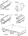
- Figures 1 to 9 attached show that it is possible to produce electrodes of any desired shape. It is indeed always possible to pass the paste having the composition according to the invention through the nozzle of a die having the desired shape and thus to obtain, for example, the desired electrode profile.
- the thicknesses and shapes of the electrode are of course suitable for the desired qualities, such as mechanical resistance, ease of diffusion of the gases, electroactivity, sealing, etc.
- the thicknesses of the electrodes are between approximately 0.05 and approximately 5 mm, preferably in the vicinity of 0.5 mm.
- the electrode can have a variable thickness, as illustrated for example in FIG. 8.
- the average diameter of the residual pores does not exceed 10 microns, the permeability being of the order of a hundred cm / h.
- a nozzle comprising a central core and an annular opening and to spin the dough in the form of a tube.
- tubular electrodes open at both ends (FIGS. 1, 5, 6, 8) or else open at one end and closed at the other end, that is to say a thermowell (FIG. 2) , or even closed at both ends.
- Their thickness can be variable (Figure 8).
- the frustoconical shape ( Figures 3 and 4) can be obtained by several methods, for example by compression, injection or extrusion blow molding in a conical mold. Tapered surfaces can be either open at both ends (Figure 3), or open at one end and closed at the other end ( Figure 4), or even closed at both ends. They may be of revolution or not of revolution and they may have either a uniform thickness or a non-uniform thickness.
- Conical or cylindrical electrodes when closed at one end (shaped like a thermowell Figures 2 and 4) can be closed by a hemispherical surface having a shape continuity with the cylindrical or conical surface.
- the current collector may consist of a metal grid, a strip of expanded metal, ribbons or filaments, a capsule.
- the captive core is placed in the mold, preferably against the walls; the captive core is preferably fixed, for example by pinching, to the mold prior to the introduction under pressure of the dough into the mold, the latter coming to surround the collector by incorporating it into its mass.
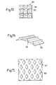
- Figures 13, 14 and 15 show three collector structures obtained by the method according to the invention, respectively honeycomb, rib and weft, these figures being partial representations in plan ( Figures 13 and 15) or in perspective ( Figure 14) of a collector portion.
- This paste is calendered between cylinders heated to 50 ° C to obtain a thick strip of 0.5 mm.
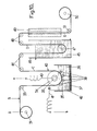
- a roller A of this strip is mounted on a mandrel 31; the unrolled strip B passes over a deflection roller 33 then over a conductive cylinder 34 disposed in an electroplating tank 35, filled with an electrolysis bath 36 containing a solution of a soluble nickel salt; a soluble nickel anode, constituted for example by nickel balls 37, is disposed in the electrolysis bath 36.
- Pressure rollers 38 apply the strip B against the conductive cylinder 34; the electric electrolysis voltage is applied between the terminals a and b respectively connected to the axis 39 of the conductive cylinder 34 by the conductor 40 and to the soluble anode, constituted by the balls 37, by a conductor 41 and a conductive plate 42 in contact with these balls.
- the electrolysis bath contains 80 g of nickel, in the form of nickel sulfonate and 30 g of boric acid, per liter of solution.
- the density of the electrodeposition current is 100 amperes / dm 2 of submerged electrode and the speed of travel of the strip B is such that each portion of electrode remains in the electrolysis bath for a period of time included between 30 seconds and several minutes, depending on the thickness of the desired nickel deposit, this deposit having to constitute the current collector. It is the face 43 of the strip B opposite the face in contact with the conductive cylinder 34 which receives the nickel deposit which will constitute the current collector.
- the strip C comprising on its face 43 the nickel deposit which constitutes the current collector, after having passed over return rollers 44, passes through a rinsing bath 45 placed in a tank 46, passing over a pulley 47.
- the cleaned strip D arrives, after passing over the return rollers 48, in a drying oven 49 in which it is dried and finally the dry electrode E is wound on a drum 50 after passing over a idler roller 51.
- This strip is then cut into portions of desired shape and dimension and it is even possible then to give it the configuration in the desired space, namely for example by compression, injection or transfer.
- This paste is injected into a mold heated to around 50 ° C, then ejected therefrom in the desired form.
- an electrode in the shape of a frustoconical glove finger is taken out of the mold (trunk of cone of re evolution, the lower part of which is closed by a hemispherical cap).
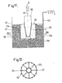
- Such an electrode is illustrated at F in FIG. 11.
- This electrode F is placed, as illustrated in FIG. 11, on a mandrel 52 which plunges into an electrolysis bath 53 having the same composition as that indicated in example I and which is placed in a tank 54.
- the assembly of the mandrel 52 of the electrode F rests on the ribs 55 of an electrode holder 56 whose periphery 57 is pierced with holes 57a to allow the passage of the electrolysis solution.
- the ribs 55 are intended to apply the electrode F against the mandrel 52, in order to improve the electrical contact between this mandrel, which is conductive, and the electrode. This is particularly visible in FIG. 12 which is a section through XII-XII in FIG. 11.
- the nickel balls 58 are arranged in the space between the tank 54 and the electrode holder 56, these balls being placed in the electrolysis bath 53 and being in electrical contact with a conductive part 59, for example made of titanium, connected by a conductor 60 at one of the electrical power supply terminals a, the other terminal b of which is connected to the mandrel 62 by a conductor 61.
- the current density applied is 100 amperes / dm 2 of submerged electrode.
- the power-up, and therefore the application of deposition, lasts between 30 seconds and 2 minutes.
- the electrode coated with the electrodeposited nickel layer is dried and then freed from the lubricant, for example by evaporation.
- the electrode which has thus just been prepared can be used very advantageously to constitute the cathode of an electrochemical generator (cell or accumulator) by associating with it an anode mass and separa. rators.
- it can be used to make generators of the type described in another patent application filed by the applicant on the same day, with the same inventor, and entitled "Electro generator chemical including a thin gas electrode ".
- the current collector a honeycomb structure (collector ⁇ 62 illustrated in part in Figure 13, on which we see ribs 63 in excess thickness intersecting at right angles by defining "boxes” 64), a ribbed structure (as visible in FIG. 14, which illustrates a portion of such a curved collector 65 comprising ribs 66 in excess thickness), in a weft (as illustrated in FIG. 15, which represents an electrode 67 comprising extra thicknesses 68 in the form of diamonds), in lattice or with tabs for example.
- Such structures make it possible to produce electrode-collector assemblies capable of better withstanding mechanical forces in a certain direction or certain directions, or of promoting conductivity in one or more directions, while not disturbing the general permeability of the electrode. thanks to the reduced thickness of the deposit in the main part of the deposit (for example between the ribs or between the diamonds).
- Non-uniform deposits in particular those according to examples III (FIG. 13), IV (FIG. 14) and V (FIG. 15) can be obtained by means of masks applied to the electrode during the electrolytic deposition, these masks being for example similar to the ribs 55 illustrated in FIGS. 11 and 12.
- the electrolysis bath indicated in these examples is replaced in Examples I and II by the following bath: 220 g / 1 of copper sulphate and 30 g / 1 of sulfuric acid, the soluble anode consisting of an electrolytic copper plate, in place of the nickel beads.
- the current density used is then several tens of amps / dm 2 .
- the electrolysis bath of Examples I and II is replaced by the following electrolysis bath: 30 g / l of silver cyanide, 70 g / l of sodium cyanide and 45 g / l of sodium carbonate, soluble anode consisting of a silver foil, instead of nickel beads; the current density used is then several tens of amps / dm 2 .
- the method according to the invention is very advantageous, because it is particularly simple, it adapts to apply a connector to an electrode of any shape, the quantity of metal deposited can be adjusted as desired and it is easily automated.
- This process produces a current collector consisting of a metallic film deposited on an electrode of any shape, the film being porous, perfectly adherent on the electrode, whatever its shape, and perfectly adapted to the conductivity. desired and the desired mechanical strength.
Landscapes
- Chemical & Material Sciences (AREA)
- Chemical Kinetics & Catalysis (AREA)
- Electrochemistry (AREA)
- General Chemical & Material Sciences (AREA)
- Engineering & Computer Science (AREA)
- Materials Engineering (AREA)
- Manufacturing & Machinery (AREA)
- Inert Electrodes (AREA)
Priority Applications (1)
| Application Number | Priority Date | Filing Date | Title |
|---|---|---|---|
| AT82400638T ATE30812T1 (de) | 1981-04-13 | 1982-04-07 | Verfahren zur herstellung von duennen elektroden, insbesondere gaselektroden, fuer elektrochemische anlagen und durch dieses verfahren erhaltene duenne elektroden, wobei die elektroden mit stromkollektoren versehen sein koennen. |
Applications Claiming Priority (4)
| Application Number | Priority Date | Filing Date | Title |
|---|---|---|---|
| FR8107408 | 1981-04-13 | ||
| FR8107407 | 1981-04-13 | ||
| FR8107407A FR2503937A1 (fr) | 1981-04-13 | 1981-04-13 | Procede de fabrication d'electrodes minces, notamment d'electrodes a gaz, pour dispositifs electrochimiques et electrodes minces obtenues par ce procede |
| FR8107408A FR2503936B1 (fr) | 1981-04-13 | 1981-04-13 | Procede de preparation de collecteurs de courant pour dispositifs electrochimiques, par depot sur des electrodes pour de tels dispositifs, et ensembles unitaires electrodes-collecteurs obtenus par ce procede |
Publications (2)
| Publication Number | Publication Date |
|---|---|
| EP0063981A1 true EP0063981A1 (de) | 1982-11-03 |
| EP0063981B1 EP0063981B1 (de) | 1987-11-11 |
Family
ID=26222329
Family Applications (1)
| Application Number | Title | Priority Date | Filing Date |
|---|---|---|---|
| EP82400638A Expired EP0063981B1 (de) | 1981-04-13 | 1982-04-07 | Verfahren zur Herstellung von dünnen Elektroden, insbesondere Gaselektroden, für elektrochemische Anlagen und durch dieses Verfahren erhaltene dünne Elektroden, wobei die Elektroden mit Stromkollektoren versehen sein können |
Country Status (6)
| Country | Link |
|---|---|
| US (1) | US4440835A (de) |
| EP (1) | EP0063981B1 (de) |
| CA (1) | CA1167518A (de) |
| DE (1) | DE3277667D1 (de) |
| MA (1) | MA19441A1 (de) |
| OA (1) | OA07073A (de) |
Families Citing this family (60)
| Publication number | Priority date | Publication date | Assignee | Title |
|---|---|---|---|---|
| DE3532286A1 (de) * | 1985-09-11 | 1987-04-16 | Dobos Karoly Dr | Anordnung von gasdiffusionselektroden und verfahren fuer die herstellung von gasdiffusionselektroden |
| WO1999058282A1 (fr) * | 1998-05-13 | 1999-11-18 | Mitsubishi Denki Kabushiki Kaisha | Electrode de briquette verte pour traitement de surface par decharge, procede de production de cette electrode, procede de traitement de surface par decharge, dispositif permettant d'appliquer ce procede et procede de recyclage de l'electrode en briquette verte pour traitement de surface par decharge |
| US6599408B1 (en) * | 1998-09-17 | 2003-07-29 | E. I. Du Pont De Nemours And Company | Thick film conductor composition for use in biosensors |
| WO2000060685A1 (en) * | 1999-03-31 | 2000-10-12 | Koninklijke Philips Electronics N.V. | Method of applying an electrically conducting current collector on a self-supporting electrode and assembly of electrode and current collector |
| US6368365B1 (en) | 2000-03-23 | 2002-04-09 | The Gillette Company | Method of making a battery |
| US7238448B1 (en) * | 2000-04-26 | 2007-07-03 | The Gillette Company | Cathode for air assisted battery |
| US6627252B1 (en) | 2000-05-12 | 2003-09-30 | Maxwell Electronic Components, Inc. | Electrochemical double layer capacitor having carbon powder electrodes |
| US6631074B2 (en) * | 2000-05-12 | 2003-10-07 | Maxwell Technologies, Inc. | Electrochemical double layer capacitor having carbon powder electrodes |
| US6643119B2 (en) * | 2001-11-02 | 2003-11-04 | Maxwell Technologies, Inc. | Electrochemical double layer capacitor having carbon powder electrodes |
| US20040048146A1 (en) * | 2002-09-06 | 2004-03-11 | David Adamson | Electrochemical cells and systems |
| US7332238B2 (en) * | 2002-09-06 | 2008-02-19 | The Gillette Company | Electrochemical cells and systems |
| US7352558B2 (en) | 2003-07-09 | 2008-04-01 | Maxwell Technologies, Inc. | Dry particle based capacitor and methods of making same |
| US20060147712A1 (en) * | 2003-07-09 | 2006-07-06 | Maxwell Technologies, Inc. | Dry particle based adhesive electrode and methods of making same |
| US7791860B2 (en) * | 2003-07-09 | 2010-09-07 | Maxwell Technologies, Inc. | Particle based electrodes and methods of making same |
| US20110165318A9 (en) * | 2004-04-02 | 2011-07-07 | Maxwell Technologies, Inc. | Electrode formation by lamination of particles onto a current collector |
| US20070122698A1 (en) * | 2004-04-02 | 2007-05-31 | Maxwell Technologies, Inc. | Dry-particle based adhesive and dry film and methods of making same |
| US7920371B2 (en) * | 2003-09-12 | 2011-04-05 | Maxwell Technologies, Inc. | Electrical energy storage devices with separator between electrodes and methods for fabricating the devices |
| RU2336603C2 (ru) * | 2003-12-04 | 2008-10-20 | Мицуи Майнинг Энд Смелтинг Ко., Лтд. | Электрод для использования во вторичной батарее, способ его изготовления и вторичная батарея |
| US7090946B2 (en) | 2004-02-19 | 2006-08-15 | Maxwell Technologies, Inc. | Composite electrode and method for fabricating same |
| US20060029530A1 (en) * | 2004-08-09 | 2006-02-09 | Gloria Gremillion | Perfect tooth brush sterilize |
| US7440258B2 (en) * | 2005-03-14 | 2008-10-21 | Maxwell Technologies, Inc. | Thermal interconnects for coupling energy storage devices |
| USD540881S1 (en) * | 2005-09-26 | 2007-04-17 | Waugh Adrian M | Perspiration-absorbing sleeve for video game controller |
| EP1826849A1 (de) * | 2006-02-24 | 2007-08-29 | Auto-Juntas, S.A. Unipersonal | Membran-Elektroden-Einheit mit verstärkter Dichtungsstruktur |
| PL1900948T3 (pl) * | 2006-09-14 | 2017-09-29 | Federal-Mogul Deva Gmbh | Łożysko przegubowe z pierścieniem zewnętrznym z tworzywa sztucznego i sposób jego wytwarzania |
| USD645889S1 (en) * | 2008-02-29 | 2011-09-27 | Ngk Insulators, Ltd. | Shaft portion of an apparatus for holding and heating semiconductor wafers or the like |
| USD623961S1 (en) * | 2009-10-09 | 2010-09-21 | Maccario Susan C | Container |
| USD684253S1 (en) * | 2011-02-24 | 2013-06-11 | Moldex-Metric, Inc. | Cylinder earplug |
| USD742209S1 (en) * | 2013-08-24 | 2015-11-03 | Richard Humm | Welded fencing straight connector |
| USD781975S1 (en) * | 2014-10-11 | 2017-03-21 | Evgenii Kurov | Hockey stick protector |
| USD740382S1 (en) * | 2014-10-22 | 2015-10-06 | Jason Bonque Koo | Golf club ferrule |
| US10054392B2 (en) | 2015-04-25 | 2018-08-21 | Samuel P. Maroney | Grip sleeve for firearm |
| USD813339S1 (en) * | 2016-04-25 | 2018-03-20 | Samuel P. Maroney | Firearm grip sleeve |
| US10847780B2 (en) * | 2016-09-16 | 2020-11-24 | Pacesetter, Inc. | Battery electrode and methods of making |
| USD833105S1 (en) * | 2016-12-13 | 2018-11-13 | Mars, Incorporated | Food product |
| USD864387S1 (en) | 2017-05-02 | 2019-10-22 | Affera, Inc. | Catheter tip with openings |
| USD831141S1 (en) * | 2017-08-14 | 2018-10-16 | H. Stetser Murphy, Jr. | Racket handle |
| USD835360S1 (en) * | 2017-09-29 | 2018-12-04 | Vuff Llc | Leash handle sleeve |
| USD831142S1 (en) * | 2017-11-27 | 2018-10-16 | H. Stetser Murphy, Jr. | Racket handle |
| US10183442B1 (en) | 2018-03-02 | 2019-01-22 | Additive Device, Inc. | Medical devices and methods for producing the same |
| USD902420S1 (en) * | 2019-02-26 | 2020-11-17 | Sweet Tech, As | Medical sheath |
| US10889053B1 (en) | 2019-03-25 | 2021-01-12 | Restor3D, Inc. | Custom surgical devices and method for manufacturing the same |
| US11844704B2 (en) | 2019-09-18 | 2023-12-19 | Restor3D, Inc. | Instruments and method for ankle replacement surgery |
| US10772732B1 (en) | 2020-01-08 | 2020-09-15 | Restor3D, Inc. | Sheet based triply periodic minimal surface implants for promoting osseointegration and methods for producing same |
| USD920515S1 (en) | 2020-01-08 | 2021-05-25 | Restor3D, Inc. | Spinal implant |
| USD920517S1 (en) | 2020-01-08 | 2021-05-25 | Restor3D, Inc. | Osteotomy wedge |
| USD920516S1 (en) | 2020-01-08 | 2021-05-25 | Restor3D, Inc. | Osteotomy wedge |
| US11554908B2 (en) | 2021-03-10 | 2023-01-17 | Susan C. Maccario | Combination dispensing and side disposal container and method |
| US11850144B1 (en) | 2022-09-28 | 2023-12-26 | Restor3D, Inc. | Ligament docking implants and processes for making and using same |
| US11806028B1 (en) | 2022-10-04 | 2023-11-07 | Restor3D, Inc. | Surgical guides and processes for producing and using the same |
| USD1051384S1 (en) | 2023-03-24 | 2024-11-12 | Restor3D, Inc. | Bone fixation pin |
| USD1053353S1 (en) | 2023-03-24 | 2024-12-03 | Restor3D, Inc. | Orthopedic screw |
| USD1118931S1 (en) | 2023-03-31 | 2026-03-17 | Restor3D, Inc. | Orthopedic implant |
| USD1130740S1 (en) | 2023-05-08 | 2026-06-16 | Restor3D, Inc. | Osteotomy guide |
| USD1124342S1 (en) | 2023-05-10 | 2026-04-28 | Restor3D, Inc. | Talus implant |
| USD1122446S1 (en) | 2023-05-10 | 2026-04-14 | Restor3D, Inc. | Talus implant |
| USD1052732S1 (en) | 2023-05-25 | 2024-11-26 | Restor3D, Inc. | Subtalar wedge |
| US12690986B1 (en) | 2023-08-08 | 2026-07-28 | Restor3D, Inc. | Total ankle replacement system and processes for making and using the same |
| US11960266B1 (en) | 2023-08-23 | 2024-04-16 | Restor3D, Inc. | Patient-specific medical devices and additive manufacturing processes for producing the same |
| US12591216B1 (en) | 2024-02-02 | 2026-03-31 | Restor3D, Inc. | Patient-specific medical devices based on bone density and processes for producing the same |
| US12605251B1 (en) | 2025-03-28 | 2026-04-21 | Restor3D, Inc. | Patient-specific shoulder implants and processes for producing and using the same |
Citations (13)
| Publication number | Priority date | Publication date | Assignee | Title |
|---|---|---|---|---|
| FR1321359A (fr) * | 1961-05-10 | 1963-03-15 | Shell Res Ltd | Perfectionnements aux électrodes |
| FR1455261A (fr) * | 1965-07-28 | 1966-04-01 | Du Pont | Pile à combustible |
| FR1457130A (fr) * | 1964-12-08 | 1966-07-08 | Shell Int Research | Piles à combustible et électrodes utilisables dans ces piles |
| US3329530A (en) * | 1964-03-25 | 1967-07-04 | Daikin Ind Ltd | Sintered fuel cell electrode comprising fluorine-containing monomer |
| FR1491996A (fr) * | 1966-09-12 | 1967-08-11 | Exxon Research Engineering Co | électrode destinée à être utilisée dans des piles électrochimiques |
| FR1522224A (fr) * | 1964-10-20 | 1968-04-26 | American Cyanamid Co | Réalisation d'électrodes pour piles à combustible |
| US3553032A (en) * | 1969-01-21 | 1971-01-05 | Sony Corp | Method of making a fuel cell electrode by thermal decomposition of silver carbonate |
| DE2111095A1 (de) * | 1971-03-09 | 1972-09-14 | Bundesrep Deutschland | Verfahren zur Herstellung einer Gasdiffusionselektrode |
| US3762957A (en) * | 1970-06-08 | 1973-10-02 | United Aircraft Corp | Method of fabricating lightweight electrodes |
| FR2224881A1 (en) * | 1973-04-05 | 1974-10-31 | Wonder | Gas diffusion electrode mfr - by moulding conductive powder with polyhaloethylene |
| US3943006A (en) * | 1973-12-27 | 1976-03-09 | Energy Research Corporation | Method of making a fuel cell electrode |
| US4205432A (en) * | 1975-11-26 | 1980-06-03 | Prazska Akumulatorka, Narodni Podnik | Method of manufacturing plastic bonded battery plates having controlled porosity |
| US4248682A (en) * | 1979-09-27 | 1981-02-03 | Prototech Company | Carbon-cloth-based electrocatalytic gas diffusion electrodes, assembly and electrochemical cells comprising the same |
Family Cites Families (18)
| Publication number | Priority date | Publication date | Assignee | Title |
|---|---|---|---|---|
| US3125468A (en) * | 1964-03-17 | figures | ||
| FR1258760A (fr) * | 1959-06-10 | 1961-04-14 | Shell Res Ltd | électrodes pour piles à électrodes combustibles |
| GB931959A (en) * | 1960-03-04 | 1963-07-24 | Kettering Found Charles F | A fuel cell |
| NL291215A (de) * | 1961-04-06 | |||
| US3235473A (en) * | 1961-12-26 | 1966-02-15 | Pullman Inc | Method of producing fuel cell electrodes |
| US3423246A (en) * | 1964-01-06 | 1969-01-21 | Exxon Research Engineering Co | Leakproof electrode |
| FR1440054A (fr) * | 1965-04-13 | 1966-05-27 | Wonder Piles | Perfectionnements apportés aux procédés de fabrication des électrodes pour pilesou accumulateurs |
| US3347708A (en) * | 1965-06-15 | 1967-10-17 | Union Carbide Corp | Fuel cell battery containing metal coated carbon electrodes |
| GB1213647A (en) * | 1967-06-27 | 1970-11-25 | Qualcast Ltd | Metal/air cells |
| GB1140635A (en) * | 1967-11-03 | 1969-01-22 | Shell Int Research | Magnesium/air electric cell |
| US3935029A (en) * | 1971-11-18 | 1976-01-27 | Energy Research Corporation | Method of fabricating a carbon - polytetrafluoroethylene electrode - support |
| US4043933A (en) * | 1976-06-15 | 1977-08-23 | United Technologies Corporation | Method of fabricating a fuel cell electrode |
| JPS53142630A (en) * | 1977-05-18 | 1978-12-12 | Sanyo Electric Co | Method of manufacturing cadmium electrode for alkaline battery |
| GB1573727A (en) * | 1978-05-19 | 1980-08-28 | Colgate Palmolive Co | Dentifrices |
| US4177159A (en) * | 1978-06-28 | 1979-12-04 | United Technologies Corporation | Catalytic dry powder material for fuel cell electrodes comprising fluorocarbon polymer and precatalyzed carbon |
| US4339325A (en) * | 1980-10-31 | 1982-07-13 | Diamond Shamrock Corporation | One pass process for forming electrode backing sheet |
| CA1208168A (en) * | 1980-10-31 | 1986-07-22 | Eltech Systems Corporation | Producing electrode active layer from active carbon particles and fibrillated polytetrafluoroethylene |
| EP0056725A3 (de) * | 1981-01-19 | 1982-08-11 | MPD Technology Corporation | Polymer-Elektrode |
-
1982
- 1982-04-07 EP EP82400638A patent/EP0063981B1/de not_active Expired
- 1982-04-07 DE DE8282400638T patent/DE3277667D1/de not_active Expired
- 1982-04-13 OA OA57661A patent/OA07073A/xx unknown
- 1982-04-13 CA CA000400874A patent/CA1167518A/en not_active Expired
- 1982-04-13 MA MA19646A patent/MA19441A1/fr unknown
- 1982-04-13 US US06/367,993 patent/US4440835A/en not_active Expired - Fee Related
Patent Citations (13)
| Publication number | Priority date | Publication date | Assignee | Title |
|---|---|---|---|---|
| FR1321359A (fr) * | 1961-05-10 | 1963-03-15 | Shell Res Ltd | Perfectionnements aux électrodes |
| US3329530A (en) * | 1964-03-25 | 1967-07-04 | Daikin Ind Ltd | Sintered fuel cell electrode comprising fluorine-containing monomer |
| FR1522224A (fr) * | 1964-10-20 | 1968-04-26 | American Cyanamid Co | Réalisation d'électrodes pour piles à combustible |
| FR1457130A (fr) * | 1964-12-08 | 1966-07-08 | Shell Int Research | Piles à combustible et électrodes utilisables dans ces piles |
| FR1455261A (fr) * | 1965-07-28 | 1966-04-01 | Du Pont | Pile à combustible |
| FR1491996A (fr) * | 1966-09-12 | 1967-08-11 | Exxon Research Engineering Co | électrode destinée à être utilisée dans des piles électrochimiques |
| US3553032A (en) * | 1969-01-21 | 1971-01-05 | Sony Corp | Method of making a fuel cell electrode by thermal decomposition of silver carbonate |
| US3762957A (en) * | 1970-06-08 | 1973-10-02 | United Aircraft Corp | Method of fabricating lightweight electrodes |
| DE2111095A1 (de) * | 1971-03-09 | 1972-09-14 | Bundesrep Deutschland | Verfahren zur Herstellung einer Gasdiffusionselektrode |
| FR2224881A1 (en) * | 1973-04-05 | 1974-10-31 | Wonder | Gas diffusion electrode mfr - by moulding conductive powder with polyhaloethylene |
| US3943006A (en) * | 1973-12-27 | 1976-03-09 | Energy Research Corporation | Method of making a fuel cell electrode |
| US4205432A (en) * | 1975-11-26 | 1980-06-03 | Prazska Akumulatorka, Narodni Podnik | Method of manufacturing plastic bonded battery plates having controlled porosity |
| US4248682A (en) * | 1979-09-27 | 1981-02-03 | Prototech Company | Carbon-cloth-based electrocatalytic gas diffusion electrodes, assembly and electrochemical cells comprising the same |
Also Published As
| Publication number | Publication date |
|---|---|
| CA1167518A (en) | 1984-05-15 |
| EP0063981B1 (de) | 1987-11-11 |
| DE3277667D1 (en) | 1987-12-17 |
| OA07073A (fr) | 1984-01-31 |
| MA19441A1 (fr) | 1982-12-31 |
| US4440835A (en) | 1984-04-03 |
Similar Documents
| Publication | Publication Date | Title |
|---|---|---|
| EP0063981B1 (de) | Verfahren zur Herstellung von dünnen Elektroden, insbesondere Gaselektroden, für elektrochemische Anlagen und durch dieses Verfahren erhaltene dünne Elektroden, wobei die Elektroden mit Stromkollektoren versehen sein können | |
| EP0063982B1 (de) | Elektrochemischer Generator mit einer dünnen Gaselektrode | |
| KR20220128947A (ko) | 광전자기 에너지 조사를 이용한 리튬 금속 전지용 애노드 전극 제조 방법 및 리튬 금속 전지용 애노드 전극 | |
| CN102666937A (zh) | 用于制造铝结构体的方法和铝结构体 | |
| US20120295169A1 (en) | Air battery and electrode | |
| FR2931298A1 (fr) | Accumulateur fer-air a mediateur lithium | |
| CH632871A5 (fr) | Electrode de zinc pour generateur electrochimique de courant. | |
| US6465133B1 (en) | Metallic porous body and method of manufacturing the same and battery current collector having the same | |
| CN103597126A (zh) | 金属多孔体、以及均包括该金属多孔体的电极材料和电池 | |
| CA2596681C (fr) | Dispositif de recombinaison catalytique des gaz pour accumulateurs alcalins a anode de zinc | |
| CH631748A5 (fr) | Procede et dispositif pour fabriquer un ruban revetu d'un metal actif. | |
| FR2602612A1 (fr) | Structure d'electrode a base d'hydroxyde de nickel, dopee au cobalt pour generateur electrochimique | |
| FR2503937A1 (fr) | Procede de fabrication d'electrodes minces, notamment d'electrodes a gaz, pour dispositifs electrochimiques et electrodes minces obtenues par ce procede | |
| FR2503936A1 (fr) | Procede de preparation de collecteurs de courant pour dispositifs electrochimiques, par depot sur des electrodes pour de tels dispositifs, et ensembles unitaires electrodes-collecteurs obtenus par ce procede | |
| KR20250044179A (ko) | 리튬-코팅된 애노드 입자 및 그의 제조 방법 | |
| CN111629847B (zh) | 具有有孔壳活性颗粒的可充电锌-空气电池 | |
| EP0538154B1 (de) | Bipolare Elektroden für Bleiakkumulator | |
| Montero-Rama et al. | Nanoporous anodic alumina-based gas diffusion layers for the electroreduction of CO2 | |
| JP5488994B2 (ja) | アルミニウム構造体の製造方法およびアルミニウム構造体 | |
| FR2858464A1 (fr) | Dispositif de recombinaison catalytique des gaz pour accumulateurs alcalins a anode de zinc | |
| CH621210A5 (en) | Assembly for electrochemical device including a plate and a support, and use of this assembly | |
| JP2012255187A (ja) | アルミニウム多孔体の製造方法及び製造装置 | |
| JP2015137373A (ja) | アルミニウム膜の製造方法及び製造装置 | |
| BE492447A (de) | ||
| FR2576454A1 (fr) | Accumulateur au plomb |
Legal Events
| Date | Code | Title | Description |
|---|---|---|---|
| PUAI | Public reference made under article 153(3) epc to a published international application that has entered the european phase |
Free format text: ORIGINAL CODE: 0009012 |
|
| AK | Designated contracting states |
Designated state(s): AT BE CH DE GB IT NL SE |
|
| 17P | Request for examination filed |
Effective date: 19830420 |
|
| RAP1 | Party data changed (applicant data changed or rights of an application transferred) |
Owner name: SOCIETE LES PILES WONDER |
|
| GRAA | (expected) grant |
Free format text: ORIGINAL CODE: 0009210 |
|
| AK | Designated contracting states |
Kind code of ref document: B1 Designated state(s): AT BE CH DE GB IT LI NL SE |
|
| REF | Corresponds to: |
Ref document number: 30812 Country of ref document: AT Date of ref document: 19871115 Kind code of ref document: T |
|
| REF | Corresponds to: |
Ref document number: 3277667 Country of ref document: DE Date of ref document: 19871217 |
|
| GBT | Gb: translation of ep patent filed (gb section 77(6)(a)/1977) | ||
| ITF | It: translation for a ep patent filed | ||
| PLBE | No opposition filed within time limit |
Free format text: ORIGINAL CODE: 0009261 |
|
| STAA | Information on the status of an ep patent application or granted ep patent |
Free format text: STATUS: NO OPPOSITION FILED WITHIN TIME LIMIT |
|
| 26N | No opposition filed | ||
| PGFP | Annual fee paid to national office [announced via postgrant information from national office to epo] |
Ref country code: SE Payment date: 19900112 Year of fee payment: 9 |
|
| PGFP | Annual fee paid to national office [announced via postgrant information from national office to epo] |
Ref country code: CH Payment date: 19900115 Year of fee payment: 9 |
|
| PGFP | Annual fee paid to national office [announced via postgrant information from national office to epo] |
Ref country code: BE Payment date: 19900208 Year of fee payment: 9 |
|
| PGFP | Annual fee paid to national office [announced via postgrant information from national office to epo] |
Ref country code: DE Payment date: 19900222 Year of fee payment: 9 |
|
| PGFP | Annual fee paid to national office [announced via postgrant information from national office to epo] |
Ref country code: GB Payment date: 19900228 Year of fee payment: 9 |
|
| PGFP | Annual fee paid to national office [announced via postgrant information from national office to epo] |
Ref country code: AT Payment date: 19900417 Year of fee payment: 9 |
|
| PGFP | Annual fee paid to national office [announced via postgrant information from national office to epo] |
Ref country code: NL Payment date: 19900430 Year of fee payment: 9 |
|
| PG25 | Lapsed in a contracting state [announced via postgrant information from national office to epo] |
Ref country code: GB Effective date: 19910407 Ref country code: AT Effective date: 19910407 |
|
| PG25 | Lapsed in a contracting state [announced via postgrant information from national office to epo] |
Ref country code: SE Effective date: 19910408 |
|
| PG25 | Lapsed in a contracting state [announced via postgrant information from national office to epo] |
Ref country code: LI Effective date: 19910430 Ref country code: CH Effective date: 19910430 Ref country code: BE Effective date: 19910430 |
|
| REG | Reference to a national code |
Ref country code: CH Ref legal event code: PUE Owner name: CIPEL Ref country code: CH Ref legal event code: PFA Free format text: WONDER |
|
| BERE | Be: lapsed |
Owner name: SOC. LES PILES WONDER Effective date: 19910430 |
|
| PG25 | Lapsed in a contracting state [announced via postgrant information from national office to epo] |
Ref country code: NL Effective date: 19911101 |
|
| GBPC | Gb: european patent ceased through non-payment of renewal fee | ||
| NLV4 | Nl: lapsed or anulled due to non-payment of the annual fee | ||
| REG | Reference to a national code |
Ref country code: CH Ref legal event code: PL |
|
| PG25 | Lapsed in a contracting state [announced via postgrant information from national office to epo] |
Ref country code: DE Effective date: 19920201 |
|
| ITTA | It: last paid annual fee | ||
| EUG | Se: european patent has lapsed |
Ref document number: 82400638.1 Effective date: 19911108 |