EP0064028A2 - Pulpit for a screen apparatus - Google Patents
Pulpit for a screen apparatus Download PDFInfo
- Publication number
- EP0064028A2 EP0064028A2 EP82810165A EP82810165A EP0064028A2 EP 0064028 A2 EP0064028 A2 EP 0064028A2 EP 82810165 A EP82810165 A EP 82810165A EP 82810165 A EP82810165 A EP 82810165A EP 0064028 A2 EP0064028 A2 EP 0064028A2
- Authority
- EP
- European Patent Office
- Prior art keywords
- housing
- bearing plate
- adjustable
- plate
- pivot
- Prior art date
- Legal status (The legal status is an assumption and is not a legal conclusion. Google has not performed a legal analysis and makes no representation as to the accuracy of the status listed.)
- Withdrawn
Links
Images


Classifications
-
- F—MECHANICAL ENGINEERING; LIGHTING; HEATING; WEAPONS; BLASTING
- F16—ENGINEERING ELEMENTS AND UNITS; GENERAL MEASURES FOR PRODUCING AND MAINTAINING EFFECTIVE FUNCTIONING OF MACHINES OR INSTALLATIONS; THERMAL INSULATION IN GENERAL
- F16M—FRAMES, CASINGS OR BEDS OF ENGINES, MACHINES OR APPARATUS, NOT SPECIFIC TO ENGINES, MACHINES OR APPARATUS PROVIDED FOR ELSEWHERE; STANDS; SUPPORTS
- F16M11/00—Stands or trestles as supports for apparatus or articles placed thereon ; Stands for scientific apparatus such as gravitational force meters
- F16M11/20—Undercarriages with or without wheels
- F16M11/2085—Undercarriages with or without wheels comprising means allowing sideward adjustment, i.e. left-right translation of the head relatively to the undercarriage
-
- A—HUMAN NECESSITIES
- A47—FURNITURE; DOMESTIC ARTICLES OR APPLIANCES; COFFEE MILLS; SPICE MILLS; SUCTION CLEANERS IN GENERAL
- A47B—TABLES; DESKS; OFFICE FURNITURE; CABINETS; DRAWERS; GENERAL DETAILS OF FURNITURE
- A47B21/00—Tables or desks for office equipment, e.g. typewriters, keyboards
- A47B21/04—Tables or desks for office equipment, e.g. typewriters, keyboards characterised by means for holding or fastening typewriters or computer equipment
- A47B21/045—Fastening means for paper sheet; Paper trays; Accessories for typists, e.g. line indicators
-
- F—MECHANICAL ENGINEERING; LIGHTING; HEATING; WEAPONS; BLASTING
- F16—ENGINEERING ELEMENTS AND UNITS; GENERAL MEASURES FOR PRODUCING AND MAINTAINING EFFECTIVE FUNCTIONING OF MACHINES OR INSTALLATIONS; THERMAL INSULATION IN GENERAL
- F16M—FRAMES, CASINGS OR BEDS OF ENGINES, MACHINES OR APPARATUS, NOT SPECIFIC TO ENGINES, MACHINES OR APPARATUS PROVIDED FOR ELSEWHERE; STANDS; SUPPORTS
- F16M11/00—Stands or trestles as supports for apparatus or articles placed thereon ; Stands for scientific apparatus such as gravitational force meters
- F16M11/02—Heads
- F16M11/04—Means for attachment of apparatus; Means allowing adjustment of the apparatus relatively to the stand
- F16M11/06—Means for attachment of apparatus; Means allowing adjustment of the apparatus relatively to the stand allowing pivoting
- F16M11/08—Means for attachment of apparatus; Means allowing adjustment of the apparatus relatively to the stand allowing pivoting around a vertical axis, e.g. panoramic heads
-
- F—MECHANICAL ENGINEERING; LIGHTING; HEATING; WEAPONS; BLASTING
- F16—ENGINEERING ELEMENTS AND UNITS; GENERAL MEASURES FOR PRODUCING AND MAINTAINING EFFECTIVE FUNCTIONING OF MACHINES OR INSTALLATIONS; THERMAL INSULATION IN GENERAL
- F16M—FRAMES, CASINGS OR BEDS OF ENGINES, MACHINES OR APPARATUS, NOT SPECIFIC TO ENGINES, MACHINES OR APPARATUS PROVIDED FOR ELSEWHERE; STANDS; SUPPORTS
- F16M11/00—Stands or trestles as supports for apparatus or articles placed thereon ; Stands for scientific apparatus such as gravitational force meters
- F16M11/20—Undercarriages with or without wheels
- F16M11/2007—Undercarriages with or without wheels comprising means allowing pivoting adjustment
- F16M11/2035—Undercarriages with or without wheels comprising means allowing pivoting adjustment in more than one direction
- F16M11/2064—Undercarriages with or without wheels comprising means allowing pivoting adjustment in more than one direction for tilting and panning
-
- A—HUMAN NECESSITIES
- A47—FURNITURE; DOMESTIC ARTICLES OR APPLIANCES; COFFEE MILLS; SPICE MILLS; SUCTION CLEANERS IN GENERAL
- A47B—TABLES; DESKS; OFFICE FURNITURE; CABINETS; DRAWERS; GENERAL DETAILS OF FURNITURE
- A47B2200/00—General construction of tables or desks
- A47B2200/0084—Accessories for tables or desks
- A47B2200/0094—Copyholder for VDU screen
Definitions
- the invention relates to a device for placing manuscripts, documents and other templates in the correct viewing distance and viewing height for ergonomically correct work on EDP and word processing systems.
- the device is attached directly to the screen device housing, clamped to or by it, or is located directly in the area of this housing.
- Devices for placing documents are known in various designs and are set up in the vicinity of data input devices in order to present the documents to the operator at a suitable viewing height and viewing distance. These devices are usually set up to the side of the terminal, supported directly on a table top, or clamped to a desk edge and carried by an articulated arm. These known devices have the disadvantage that they require space on the table or, in the case of an articulated arm, the pivot point of the storage plate is located too far back on the edge of the desk and so the manuscript cannot always be presented at the viewing angle which is most favorable for the eye, especially if it is to be partially positioned in front of the screen. These constructions are also not sufficiently stably fastened, and without additionally holding the storage plate, e.g. not written or stamped on the manuscripts by hand, what z. Part of the practice requires, especially when short information from numerous manuscripts or templates is entered into the data device, e.g. in payment transactions in banking institutions.
- the invention is based on the object of designing a device of the type described above design that no storage space is required on the workstation for the manuscript or its holder, that the storage plate of the manuscript holder is sufficiently fixed so that notes can be affixed freehand on the manuscript, and that the manuscript easily in the individual optimal position for ergonomically correct Work can be brought.
- the requirement for the manuscript holder to take up little space on data terminals is met in such a way that the manuscript holder is clamped laterally, for example directly on the terminal housing, by adjustable support arms and its pivot bearing plate is supported on the top of the housing.
- the shelf can be positioned along the sides of the housing and also does not require any usable space.
- parts of the manuscript holder can be weighed down by the dead weight of the terminal, in that these parts are designed as feet, floor brackets etc. and are pushed under the terminal.
- the pivot point of the pivot arm can be attached to a telescopic frame and this can be anchored in the desk or on a desk edge.
- the requirement for the manuscript to be positioned at the optimum viewing angle for ergonomically correct work is met, for example, by the height-adjustable storage plate being connected to a rotating arm with a slot guide by a joint that can be moved on all sides, which moves with larger or smaller radii in a circle around the front of the terminal and can be locked in any position.
- the pivot point of the rotating arm can also be shifted laterally, for example in a slot guide, so that there is great flexibility in the positioning of the manuscript.
- the requirement of sufficient fixation of the Manuskri D t-plate was met by the rotating arm on a second point is locked in the fulcrum bearing plate, in a second fastening slot guide parallel to the fulcrum slot guide with a movable fastening point or in individual pivot or fastening bearing points.
- the axis of rotation of the manuscript plate is also locked at a second point, for example in a circular groove running centrally to the plate axis with a bolt and nut.
- the manuscript itself is placed on the edge of the shelf and fixed with a clip, for example.
- the storage plate does not necessarily have to be flat, a roller can also be used, which gives the manuscript sheet a curved shape, thus requires less space and is even more suitable for placement in front of a data device.
- Figures 1 + 2 show a monitor housing (1) without keyboard in front view and floor plan.
- a pivot bearing plate (2) with longitudinal guides (3) in which the displaceable support arms (4) are adjusted to the respective housing width is placed on the housing (1) and can be clamped to the slotted longitudinal guides (3) using locking screws (5), for example. It can be fixed to the housing using set screws (6) and rubber buffers (7) or similar elements.
- the fulcrum bearing plate (2) has two grooves (8) which serve as a guide for the laterally displaceable pivot and fastening pins with nuts (9) of the pivot arm (10).
- the rotating arm (10) has, for example, a slot (11) for changing its turning radius.
- the rotary arm (10) can be subdivided, for example connected by a joint (12) which can be moved on all sides, as a result of which the angle of inclination of the storage plate (13) can be changed and, after the positioning has been carried out, it can still be finely aligned.
- the holder (14) of the storage plate (13) has a pivot point (15) and a circular groove (16). The plate (13) can thus be rotated around the pivot point (15) for the purpose of adjustment and locked in the circular groove (16) with a bolt and nut (17, 18).
- the height of the plate (13) can, for example, be leveled in the slot guide (19) of the holder (14).
- Figure 3 shows the device in side view in the version with floor bracket.
- This variant is independent of the width of the housing (1) and therefore requires no support arms, but a length and height adjustable bracket device (20), which serves as a connection between the pivot plate (2) and the floor bracket (21). If you do not want to equip the device with a floor bracket or extended bracket, you can e.g. like a dotted line, a clamp (22) will take its place. If the bracket device (20) is sufficiently stable, the fulcrum bearing plate (2) can also be located above the terminal housing (1) without any contact with the terminal housing.
- FIG. 4 shows a front view of the device with terminal housing (1) in a further variant, in that the bracket device (23) is guided laterally under the housing (1).
- Figure 5 shows the attachment of the support arm (4) on the terminal housing (1) with sloping side surfaces (25).
- the support point for the set screw (26) is e.g. a rubber buffer (27) glued to the side surface.
Landscapes
- Engineering & Computer Science (AREA)
- General Engineering & Computer Science (AREA)
- Mechanical Engineering (AREA)
- Computer Hardware Design (AREA)
- Facsimile Scanning Arrangements (AREA)
- Facsimiles In General (AREA)
- Holders For Sensitive Materials And Originals (AREA)
- Casings For Electric Apparatus (AREA)
Abstract
Die Drehpunktlagerplatte (2) des Manuskripthalters wird auf das Terminalgehäuse (1) aufgelegt, durch einstellbare Tragarme (4) und Arretierschrauben (5) auf die Gehäusebreite abgestimmt und mit Stellschrauben (6) und Gummipuffern (7) angeklemmt. Durch den einstellbaren Dreharm (10) und unter Berücksichtigung des günstigsten Abstandes A des Drehzentrums (9) von der Bildröhre (28) kann die Ablageplatte (13) mit passendem Radius kreisförmig um die Bildröhre oder durch Drehpunktverschiebung in den Nuten (8) geradlinig entlang der Bildröhre (28) verschoben werden. Die höhenverstellbare Ablageplatte (13) ist arretierbar mittels Kreisnut (16), Mutter und Bolzen (17,18) und der Dreharm (10) mit den beiden Befestigungszapfen (9). Ein allseitig bewegliches Gelenk (12) ermöglicht die Feineinstellung nach der Positionierung in der ergonomisch korrekten Leselage.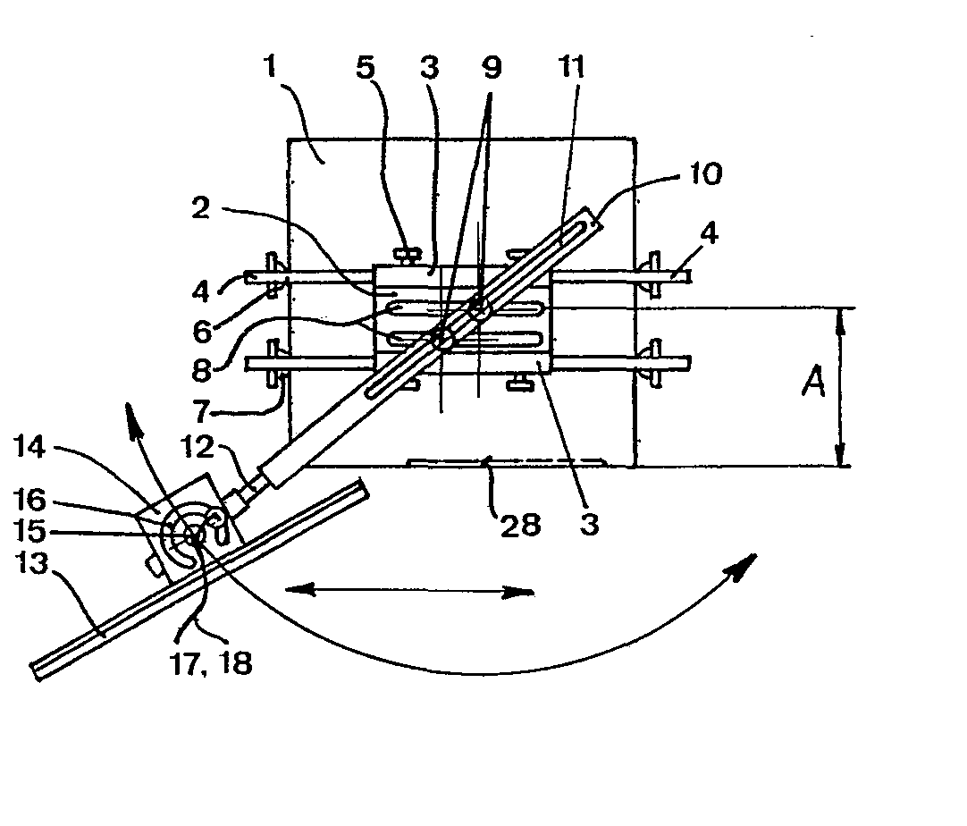
Description
Die Erfindung betrifft eine Vorrichtung zum Auflegen von Manuskripten, Dokumenten und sonstigen Vorlagen in richtiger Sichtdistanz und Sichthöhe für ergonomisch korrektes Arbeiten an EDV- und Textverarbeitungssystemen. Die Vorrichtung wird dabei direkt am Bildschirmgerätegehäuse angebracht, an oder durch dieses festgeklemmt, oder befindet sich unmittelbar im Bereich dieses Gehäuses.The invention relates to a device for placing manuscripts, documents and other templates in the correct viewing distance and viewing height for ergonomically correct work on EDP and word processing systems. The device is attached directly to the screen device housing, clamped to or by it, or is located directly in the area of this housing.
Vorrichtungen zum Auflegen von Dokumenten sind in verschiedenen Ausführungen bekannt und werden in der Nähe von Dateneingabegeräten aufgestellt um der Bedienungsperson die Dokumente in geeigneter Sichthöhe und Sichtdistanz darzubieten. Diese Vorrichtungen sind meist seitlich des Terminals aufgestellt, direkt auf eine Tischplatte abgestützt, oder an eine Pultkante geklemmt und durch einen Gelenkarm getragen. Diese bekannten Vorrichtungen haben den Nachteil, dass sie Platz auf dem Tisch benötigen oder im Falle eines Gelenkarmes sich der Drehpunkt der Ablageplatte zu weit hinten an der Pultkante befindet und so das Manuskript nicht in jedem Fall in dem für das Auge günstigsten Sichtwinkel präsentiert werden kann, speziell wenn es partiell vor dem Bildschirm positioniert werden soll. Auch sind diese Konstruktionen nicht genügend stabil befestigt, und ohne die Ablageplatte zusätzlich zu halten, kann z.B. auf den Manuskripten nicht freihändig geschrieben oder gestempelt werden, was z. Teil die Praxis verlangt, speziell wenn kurze Informationen von zahlreichen Manuskripten oder Vorlagen in das Datengerät eingegeben werden, wie z.B. beim Zahlungsverkehr in Bankinstituten.Devices for placing documents are known in various designs and are set up in the vicinity of data input devices in order to present the documents to the operator at a suitable viewing height and viewing distance. These devices are usually set up to the side of the terminal, supported directly on a table top, or clamped to a desk edge and carried by an articulated arm. These known devices have the disadvantage that they require space on the table or, in the case of an articulated arm, the pivot point of the storage plate is located too far back on the edge of the desk and so the manuscript cannot always be presented at the viewing angle which is most favorable for the eye, especially if it is to be partially positioned in front of the screen. These constructions are also not sufficiently stably fastened, and without additionally holding the storage plate, e.g. not written or stamped on the manuscripts by hand, what z. Part of the practice requires, especially when short information from numerous manuscripts or templates is entered into the data device, e.g. in payment transactions in banking institutions.
Der Erfindung liegt nun die Aufgabe zugrunde, eine Vorrichtung der eingangs beschriebenen Art so auszugestalten, dass kein Ablageraum auf dem Arbeitsplatz für das Manuskript bzw. dessen Halter benötigt wird, dass die Ablageplatte des Manuskripthalters genügend fixiert ist, damit auf dem Manuskript freihändig Vermerke angebracht werden können, und dass das Manuskript leicht in die individuelle optimale Lage für ergonomisch korrektes Arbeiten gebracht werden kann. Der Forderung nach geringer Platzbeanspruchung des Manuskripthalters an Datenterminals wird so entsprochen, dass der Manuskripthalter z.B. direkt am Terminalgehäuse durch einstellbare Trägerarme seitlich angeklemmt und dessen Drehpunktlagerplatte oben auf das Gehäuse abgestützt wird. Bei Nichtgebrauch kann die Ablageplatte längs der Gehäuseseiten stationiert werden und benötigt ebenfalls keinen nutzbaren Raum. Auch ist es möglich, dass Teile des Manuskripthalters durch das Eigengewicht des Terminals beschwert werden, indem diese Teile als Füsse, Bodenhalterung usw. ausgebildet werden und unter das Terminal geschoben werden. Oder es kann die Drehpunktlagerplatte des Dreharmes an ein Teleskopbügelgestell befestigt und dieses im Pult oder an einer Pultkante verankert werden. Der Forderung nach der Positionierung des Manuskriptes im optimalen Sichtwinkel für ergonomisch korrektes Arbeiten wird z.B. dadurch erfüllt, dass die höhenverstellbare Ablageplatte durch ein allseitig bewegliches Gelenk mit einem Dreharm mit Schlitzführung verbunden ist, welcher mit grösseren oder kleineren Radien kreisförmig um die Vorderseite des Terminals bewegt und in beliebiger Lage arretiert werden kann. Zudem kann der Drehpunkt des Dreharmes seitlich ebenfalls z.B. in einer Schlitzführung verschoben werden, sodass sich eine grosse Beweglichkeit in der Positionierung des Manuskriptes ergibt.The invention is based on the object of designing a device of the type described above design that no storage space is required on the workstation for the manuscript or its holder, that the storage plate of the manuscript holder is sufficiently fixed so that notes can be affixed freehand on the manuscript, and that the manuscript easily in the individual optimal position for ergonomically correct Work can be brought. The requirement for the manuscript holder to take up little space on data terminals is met in such a way that the manuscript holder is clamped laterally, for example directly on the terminal housing, by adjustable support arms and its pivot bearing plate is supported on the top of the housing. When not in use, the shelf can be positioned along the sides of the housing and also does not require any usable space. It is also possible for parts of the manuscript holder to be weighed down by the dead weight of the terminal, in that these parts are designed as feet, floor brackets etc. and are pushed under the terminal. Or the pivot point of the pivot arm can be attached to a telescopic frame and this can be anchored in the desk or on a desk edge. The requirement for the manuscript to be positioned at the optimum viewing angle for ergonomically correct work is met, for example, by the height-adjustable storage plate being connected to a rotating arm with a slot guide by a joint that can be moved on all sides, which moves with larger or smaller radii in a circle around the front of the terminal and can be locked in any position. In addition, the pivot point of the rotating arm can also be shifted laterally, for example in a slot guide, so that there is great flexibility in the positioning of the manuscript.
Der Forderung nach genügender Fixierung der ManuskriDt-platte wurde entsprochen, indem der Dreharm an einem zweiten Punkt in der Drehpunktlagerplatte arretiert wird, in einer zur Drehpunktschlitzführung parallelen zweiten Befestigungsschlitzführung mit beweglichem Befestigungspunkt oder in einzelnen Dreh- bzw. Befestigungslagerstellen. Zudem wird die Drehachse der Manuskriptplatte ebenfalls an einem zweiten Punkt arretiert, dies z.B. in einer zentrisch zur Plattenachse verlaufenden Kreisnut mit Bolzen und Mutter. Das Manuskript selbst wird dabei auf den Rand der Ablageplatte gelegt und z.B. mit einer Klammer fixiert.The requirement of sufficient fixation of the Manuskri D t-plate was met by the rotating arm on a second point is locked in the fulcrum bearing plate, in a second fastening slot guide parallel to the fulcrum slot guide with a movable fastening point or in individual pivot or fastening bearing points. In addition, the axis of rotation of the manuscript plate is also locked at a second point, for example in a circular groove running centrally to the plate axis with a bolt and nut. The manuscript itself is placed on the edge of the shelf and fixed with a clip, for example.
Die Ablageplatte muss nicht zwangsweise eben sein, es kann auch eine Walze verwendet werden, wodurch das Manuskriptblatt eine gebogene Form erhält, somit weniger Raum benötigt und noch besser für eine Plazierung vor der Frontseite eines Datengerätes geeignet ist.The storage plate does not necessarily have to be flat, a roller can also be used, which gives the manuscript sheet a curved shape, thus requires less space and is even more suitable for placement in front of a data device.
Die Erfindung ist in den Zeichnungen zusammen mit den Datenterminalgehäusen, ohne Tastatur wie folgt gezeigt:
Figur 1 in der Vorderansicht mit seitlicher Klemmbefestigung am Gehäuse.Figur 2 im Grundriss mit Klemmbefestigung am Gehäuse.Figur 3 in der Seitenansicht als Ausführung mit Bügelgestänge und Bodenhalterung.Figur 4 in der Vorderansicht als weitere Variante mit Bodenhalterung.Figur 5 in der Vorderansicht als Detail einer Befestigung an einem Gehäuse mit schrägen Seitenflächen.
- Figure 1 in a front view with lateral clamp on the housing.
- Figure 2 in plan with clamp on the housing.
- Figure 3 in side view as a version with bar linkage and floor bracket.
- Figure 4 in the front view as a further variant with floor bracket.
- Figure 5 in front view as a detail of an attachment to a housing with sloping side surfaces.
Die Figuren 1 + 2 zeigen ein Bildschirmgehäuse (1) ohne Tastatur in Frontansicht und Grundriss. Auf das Gehäuse (1) aufgesetzt ist eine Drehpunktlagerplatte (2) mit Längsführungen (3) in welchen die verschiebbaren Tragarme (4) auf die jeweilige Gehäusebreite eingestellt und z.B. mittels Arretierschrauben (5) an die geschlitzten Längsführungen (3) geklemmt werden. Die Fixierung an das Gehäuse kann z.B. mit Stellschrauben (6) und Gummipuffern (7) oder ähnlichen Elementen erfolgen. Die Drehpunktlagerplatte (2) weist zwei Nuten (8) auf, welche als Führung für die seitlich verschiebbaren Dreh- und Befestigungszapfen mit Muttern (9) des Dreharmes (10) dienen. Der Dreharm (10) weist zur Veränderung seines Drehradius' z.B. einen Schlitz (11) auf. Der Dreharm (10) kann unterteilt sein, verbunden z.B. durch ein allseitig bewegliches Gelenk (12) wodurch der Neigungswinkel der Ablageplatte (13) verändert und diese nach erfolgter Positionierung noch fein ausgerichtet werden kann. Der Halter (14) der Ablageplatte (13) weist einen Drehpunkt (15) und eine Kreisnut (16) auf. Die Platte (13) kann so um den Drehpunkt (15) zwecks Einstellung gedreht, und in der Kreisnut (16) mit Bolzen und Mutter (17,18) arretiert werden. Die Höhenlage der Platte (13) kann z.B. in der Schlitzführung (19) des Halters (14) nivelliert werden.Figures 1 + 2 show a monitor housing (1) without keyboard in front view and floor plan. A pivot bearing plate (2) with longitudinal guides (3) in which the displaceable support arms (4) are adjusted to the respective housing width is placed on the housing (1) and can be clamped to the slotted longitudinal guides (3) using locking screws (5), for example. It can be fixed to the housing using set screws (6) and rubber buffers (7) or similar elements. The fulcrum bearing plate (2) has two grooves (8) which serve as a guide for the laterally displaceable pivot and fastening pins with nuts (9) of the pivot arm (10). The rotating arm (10) has, for example, a slot (11) for changing its turning radius. The rotary arm (10) can be subdivided, for example connected by a joint (12) which can be moved on all sides, as a result of which the angle of inclination of the storage plate (13) can be changed and, after the positioning has been carried out, it can still be finely aligned. The holder (14) of the storage plate (13) has a pivot point (15) and a circular groove (16). The plate (13) can thus be rotated around the pivot point (15) for the purpose of adjustment and locked in the circular groove (16) with a bolt and nut (17, 18). The height of the plate (13) can, for example, be leveled in the slot guide (19) of the holder (14).
Die Figur 3 zeigt die Vorrichtung in Seitenansicht in der Ausführung mit Bodenhalterung. Diese Variante ist von der Breite des Gehäuses (1) unabhängig und benötigt deshalb keine Tragarme, jedoch eine längen- und höhenverstellbare Bügeleinrichtung (20), welche als Verbindung zwischen der Drehlagerplatte (2) und der Bodenhalterung (21) dient. Will man die Vorrichtung nicht mit einer Bodenhalterung bzw. verlängerter Bügeleinrichtung ausrüsten, so kann z.B. wie punktiert gezeichnet eine Klemmzwinge (22) an ihre Stelle treten. Bei genügend stabiler Ausführung der Bügeleinrichtung (20) kann die Drehpunktlagerplatte (2) auch überhalb des Terminalgehäuses (1), ohne Berührungskontakt mit demselben lokalisiert sein.Figure 3 shows the device in side view in the version with floor bracket. This variant is independent of the width of the housing (1) and therefore requires no support arms, but a length and height adjustable bracket device (20), which serves as a connection between the pivot plate (2) and the floor bracket (21). If you do not want to equip the device with a floor bracket or extended bracket, you can e.g. like a dotted line, a clamp (22) will take its place. If the bracket device (20) is sufficiently stable, the fulcrum bearing plate (2) can also be located above the terminal housing (1) without any contact with the terminal housing.
Figur 4 zeigt eine Vorderansicht der Vorrichtung mit Terminalgehäuse (1) in einer weiteren Variante, indem die Bügeleinrichtung (23) seitlich unter das Gehäuse (1) geführt wird.FIG. 4 shows a front view of the device with terminal housing (1) in a further variant, in that the bracket device (23) is guided laterally under the housing (1).
Figur 5 zeigt die Befestigung des Tragarmes (4) am Terminalgehäuse (1) mit schrägen Seitenflächen (25). Als Auflagestelle für die Stellschraube (26) dient z.B. ein an die Seitenfläche geklebter Gummipuffer (27).Figure 5 shows the attachment of the support arm (4) on the terminal housing (1) with sloping side surfaces (25). The support point for the set screw (26) is e.g. a rubber buffer (27) glued to the side surface.
Claims (10)
Applications Claiming Priority (4)
| Application Number | Priority Date | Filing Date | Title |
|---|---|---|---|
| CH2678/81 | 1981-04-24 | ||
| CH267881 | 1981-04-24 | ||
| CH5737/81 | 1981-09-07 | ||
| CH573781 | 1981-09-07 |
Publications (2)
| Publication Number | Publication Date |
|---|---|
| EP0064028A2 true EP0064028A2 (en) | 1982-11-03 |
| EP0064028A3 EP0064028A3 (en) | 1983-08-10 |
Family
ID=25691124
Family Applications (1)
| Application Number | Title | Priority Date | Filing Date |
|---|---|---|---|
| EP82810165A Withdrawn EP0064028A3 (en) | 1981-04-24 | 1982-04-21 | Pulpit for a screen apparatus |
Country Status (1)
| Country | Link |
|---|---|
| EP (1) | EP0064028A3 (en) |
Cited By (11)
| Publication number | Priority date | Publication date | Assignee | Title |
|---|---|---|---|---|
| WO1994029123A1 (en) * | 1993-06-10 | 1994-12-22 | Caderas Jean Francois | Paper tray support unit |
| WO1996011808A1 (en) * | 1994-10-18 | 1996-04-25 | Minnesota Mining And Manufacturing Company | Adjustable paper holder |
| WO1997021954A1 (en) * | 1995-12-12 | 1997-06-19 | David Payne | Support apparatus |
| GB2314499A (en) * | 1996-06-28 | 1998-01-07 | Audio And Vision Furniture Ltd | Support bracket for a loudspeaker |
| DE10337818B4 (en) * | 2003-08-18 | 2005-05-19 | Cherkasky, Yakiv, Dipl.-Ing. | Paper holder for a computer with free-standing monitor |
| DE102008013025A1 (en) | 2008-03-07 | 2009-09-24 | Cherkasky, Yakiv, Dipl.-Ing. | Paper holder for computer, has transverse projections symmetrically placed with respect to axis of symmetry of rail, where each pair of projections comprises elevation of axis, and supporting arm has double fold for adjustment of keyboard |
| DE102008039501A1 (en) | 2008-08-23 | 2010-02-25 | Cherkasky, Yakiv, Dipl.-Ing. | Monitor i.e. flat screen, for computer, has paper holder provided with moving carrier arm, bookrest and line indicator, where moving carrier arm provides round and translation movement of holder at lock tab of monitor |
| DE102011014802A1 (en) | 2011-03-23 | 2013-02-14 | Yakiv Cherkasky | Supporting stand for notebook or monitor, comprises support for its positioning with details for elevation of its rear side, where surface of support has holes for passage of air for cooling notebook |
| EP2168779A3 (en) * | 2008-09-30 | 2014-01-01 | Bakker Elkhuizen Innovations B.V. | Document holder |
| AT520132A1 (en) * | 2017-07-07 | 2019-01-15 | Norman Gaenser | Holder for smartphones |
| CN112797271A (en) * | 2021-01-11 | 2021-05-14 | 江西服装学院 | New media-based projection device of interest-swimming-river system |
Family Cites Families (4)
| Publication number | Priority date | Publication date | Assignee | Title |
|---|---|---|---|---|
| FR462673A (en) * | 1913-09-08 | 1914-02-02 | Alois Lamer | Reading desk |
| FR648104A (en) * | 1928-02-02 | 1928-12-05 | Copy holder for typewriters | |
| GB481675A (en) * | 1936-09-17 | 1938-03-16 | Thomas Lewis Coppock | Copy-holder for use with typewriters, and calculating machines |
| CH306660A (en) * | 1953-04-04 | 1955-04-30 | Balmer Victor | Manuscript holder for typewriters or typesetting machines. |
-
1982
- 1982-04-21 EP EP82810165A patent/EP0064028A3/en not_active Withdrawn
Cited By (16)
| Publication number | Priority date | Publication date | Assignee | Title |
|---|---|---|---|---|
| WO1994029123A1 (en) * | 1993-06-10 | 1994-12-22 | Caderas Jean Francois | Paper tray support unit |
| FR2706361A1 (en) * | 1993-06-10 | 1994-12-23 | Caderas Jean Francois | Metal structure adaptable to computer and office equipment, and intended to receive mail baskets. |
| WO1996011808A1 (en) * | 1994-10-18 | 1996-04-25 | Minnesota Mining And Manufacturing Company | Adjustable paper holder |
| US5620162A (en) * | 1994-10-18 | 1997-04-15 | Minnesota Mining And Manufacturing Company | Adjustable paper holder |
| WO1997021954A1 (en) * | 1995-12-12 | 1997-06-19 | David Payne | Support apparatus |
| GB2314499A (en) * | 1996-06-28 | 1998-01-07 | Audio And Vision Furniture Ltd | Support bracket for a loudspeaker |
| GB2314499B (en) * | 1996-06-28 | 1999-12-29 | Audio And Vision Furniture Ltd | Supporting assembly |
| DE10337818B4 (en) * | 2003-08-18 | 2005-05-19 | Cherkasky, Yakiv, Dipl.-Ing. | Paper holder for a computer with free-standing monitor |
| DE102008013025A1 (en) | 2008-03-07 | 2009-09-24 | Cherkasky, Yakiv, Dipl.-Ing. | Paper holder for computer, has transverse projections symmetrically placed with respect to axis of symmetry of rail, where each pair of projections comprises elevation of axis, and supporting arm has double fold for adjustment of keyboard |
| DE102008039501A1 (en) | 2008-08-23 | 2010-02-25 | Cherkasky, Yakiv, Dipl.-Ing. | Monitor i.e. flat screen, for computer, has paper holder provided with moving carrier arm, bookrest and line indicator, where moving carrier arm provides round and translation movement of holder at lock tab of monitor |
| EP2168779A3 (en) * | 2008-09-30 | 2014-01-01 | Bakker Elkhuizen Innovations B.V. | Document holder |
| DE102011014802A1 (en) | 2011-03-23 | 2013-02-14 | Yakiv Cherkasky | Supporting stand for notebook or monitor, comprises support for its positioning with details for elevation of its rear side, where surface of support has holes for passage of air for cooling notebook |
| AT520132A1 (en) * | 2017-07-07 | 2019-01-15 | Norman Gaenser | Holder for smartphones |
| AT520132B1 (en) * | 2017-07-07 | 2019-05-15 | Norman Gaenser | Holder for smartphones |
| CN112797271A (en) * | 2021-01-11 | 2021-05-14 | 江西服装学院 | New media-based projection device of interest-swimming-river system |
| CN112797271B (en) * | 2021-01-11 | 2022-10-18 | 江西服装学院 | New media-based projection device of interest-swimming-river system |
Also Published As
| Publication number | Publication date |
|---|---|
| EP0064028A3 (en) | 1983-08-10 |
Similar Documents
| Publication | Publication Date | Title |
|---|---|---|
| EP3193315B1 (en) | Checkout system with pivoting arms | |
| DE3036852A1 (en) | DEVICE FOR SETTING UP A VIEWING DEVICE ON A WORKTOP | |
| WO2003030683A1 (en) | Pivotable board provided with legs | |
| EP0064028A2 (en) | Pulpit for a screen apparatus | |
| EP0298221A2 (en) | Apparatus for milling grooves | |
| DE68926348T2 (en) | DESIGN / COPY HOLDER | |
| EP0332762A1 (en) | Apparatus support | |
| DE20009691U1 (en) | Holder for data display devices, in particular for flat screens | |
| EP0467383A1 (en) | Grinding device | |
| DE2606397C3 (en) | Support frames for the transport of panels, in particular glass panels | |
| DE3742547A1 (en) | Invalid chair with pivotable perforated plate in separate attachment frame | |
| EP0017222A1 (en) | Writing-table | |
| EP0019243B1 (en) | Stand for projection screens | |
| DE3444795A1 (en) | Stand for receiving a portable angular cutting-off machine | |
| DE3826534A1 (en) | Reading device for books | |
| EP0319656B1 (en) | Supporting and carrying handle for video displey sets | |
| DE4217823A1 (en) | Template for angled cutting of guttering for dormer windows - consists of baseplate with second plate hinged along one edge to it to form adjustable angle between two plates | |
| DE19818424C2 (en) | Holder for books | |
| EP0226869A1 (en) | Device for supporting instruments on a work surface | |
| EP0263999B1 (en) | Keyboard-supporting console | |
| DE3145942A1 (en) | Work table with table frame and worktop | |
| WO1999040838A1 (en) | Ophthalmological examination unit | |
| DE8010161U1 (en) | SCREEN WORK TABLE | |
| DE344828C (en) | Drawing board for one-armed people | |
| DE2539713A1 (en) | Adjustable drawing office table - has support frame with lockable scissor and parallelogram guide linkages |
Legal Events
| Date | Code | Title | Description |
|---|---|---|---|
| PUAI | Public reference made under article 153(3) epc to a published international application that has entered the european phase |
Free format text: ORIGINAL CODE: 0009012 |
|
| AK | Designated contracting states |
Designated state(s): AT BE CH DE FR GB IT NL SE |
|
| PUAL | Search report despatched |
Free format text: ORIGINAL CODE: 0009013 |
|
| AK | Designated contracting states |
Designated state(s): AT BE CH DE FR GB IT LI NL SE |
|
| STAA | Information on the status of an ep patent application or granted ep patent |
Free format text: STATUS: THE APPLICATION IS DEEMED TO BE WITHDRAWN |
|
| 18D | Application deemed to be withdrawn |
Effective date: 19840718 |