EP0064038A1 - Procédé et dispositif pour amortir des ondes compressives - Google Patents
Procédé et dispositif pour amortir des ondes compressives Download PDFInfo
- Publication number
- EP0064038A1 EP0064038A1 EP82850060A EP82850060A EP0064038A1 EP 0064038 A1 EP0064038 A1 EP 0064038A1 EP 82850060 A EP82850060 A EP 82850060A EP 82850060 A EP82850060 A EP 82850060A EP 0064038 A1 EP0064038 A1 EP 0064038A1
- Authority
- EP
- European Patent Office
- Prior art keywords
- compressive stress
- chamber
- stress waves
- waves
- dampening
- Prior art date
- Legal status (The legal status is an assumption and is not a legal conclusion. Google has not performed a legal analysis and makes no representation as to the accuracy of the status listed.)
- Withdrawn
Links
Images
Classifications
-
- F—MECHANICAL ENGINEERING; LIGHTING; HEATING; WEAPONS; BLASTING
- F01—MACHINES OR ENGINES IN GENERAL; ENGINE PLANTS IN GENERAL; STEAM ENGINES
- F01B—MACHINES OR ENGINES, IN GENERAL OR OF POSITIVE-DISPLACEMENT TYPE, e.g. STEAM ENGINES
- F01B11/00—Reciprocating-piston machines or engines without rotary main shaft, e.g. of free-piston type
- F01B11/02—Equalising or cushioning devices
-
- B—PERFORMING OPERATIONS; TRANSPORTING
- B25—HAND TOOLS; PORTABLE POWER-DRIVEN TOOLS; MANIPULATORS
- B25D—PERCUSSIVE TOOLS
- B25D17/00—Details of, or accessories for, portable power-driven percussive tools
- B25D17/24—Damping the reaction force
-
- F—MECHANICAL ENGINEERING; LIGHTING; HEATING; WEAPONS; BLASTING
- F01—MACHINES OR ENGINES IN GENERAL; ENGINE PLANTS IN GENERAL; STEAM ENGINES
- F01B—MACHINES OR ENGINES, IN GENERAL OR OF POSITIVE-DISPLACEMENT TYPE, e.g. STEAM ENGINES
- F01B11/00—Reciprocating-piston machines or engines without rotary main shaft, e.g. of free-piston type
- F01B11/04—Engines combined with reciprocatory driven devices, e.g. hammers
-
- F—MECHANICAL ENGINEERING; LIGHTING; HEATING; WEAPONS; BLASTING
- F16—ENGINEERING ELEMENTS AND UNITS; GENERAL MEASURES FOR PRODUCING AND MAINTAINING EFFECTIVE FUNCTIONING OF MACHINES OR INSTALLATIONS; THERMAL INSULATION IN GENERAL
- F16F—SPRINGS; SHOCK-ABSORBERS; MEANS FOR DAMPING VIBRATION
- F16F7/00—Vibration-dampers; Shock-absorbers
- F16F7/01—Vibration-dampers; Shock-absorbers using friction between loose particles, e.g. sand
- F16F7/015—Vibration-dampers; Shock-absorbers using friction between loose particles, e.g. sand the particles being spherical, cylindrical or the like
Definitions
- This invention relates to a method and a device of dampening compressive stress waves that propagate through an elongate element, for example a drill stem for rock drilling as a result of frequent impacts from a power operated hammer.
- the output energy should preferably also be checked. Sometimes, it is also desirable to check the output energy at the worksite.
- the testing is carried out in a bench for the percussion tool. A work tool with a flat front surface is used which takes support against an oil chamber. The compressive stress waves that propagate through the work tool are reflected at the end of the work tool so that a considerable part of the impact energy is given back to the impact piston of the percussion tool and makes the impact piston bounce back from its anvil. This differs from normal working conditions and reduces the validity of the testing.
- an object of the invention to make it possible to dampen compressive stress waves more effectively and an ancillary object is to make it possible to test and check an impact device for example a percussive rock drill or jack hammer under conditions that are similar to normal working conditions.
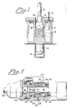
- thermometer 19 When either the output power or the impact energy per blow of a percussive rock drill is to be checked, the normal drill bit is removed and a similar bit 20 without inserts is mounted on the end of the drill rod 21 of the rock drill.
- the housing 11 is inserted in the rock as shown in Fig 1 and the feed force is applied to the rock drill. The rock drill is then operated for a predetermined period of time and the temperature rise in the liquid is noted.
- the housing 11 can be solid and a thermoelement can he attached directly to the housing 11 and permit for remote reading of the temperature rise.
- the compression related to the stress wave is usually 1-2 mm for an ordinary rock drill and when a compressive stress wave reaches the plate 16, the plate is forced forwardly the corresponding length e.g. 1.5 mm at a speed of about half the piston impact velocity i.e. normally at a speed of 4-5 m/s.
- the steel balls just beyond the plate 16 are forced downwardly 1.5 mm, whereas the balls at the bottom cannot move.
- the movement results in elastic deformation of the balls and frictional movement between the outer balls and the envelop wall. Some frictional movements between the balls take also place.
- the compressive stress wave When,the compressive stress wave is over, the balls force the plate 16 back to its initial position and frictional movements occur also during this return phase.
- the plate 16 For a normal impact frequency of about 50 Hz, the plate 16 is well back in its initial position before the next compressive stress wave reaches the plate Since the normal impact frequency for a rock drill or jack hammer is 10-100 Hz, the useful length of a compressive stress wave is usually about 1 m or less, and the waves move at about 5000 m/s, there is a relatively long time between the waves.
- the areas of the drill bit 20, the plate 16 and the chamber 18 can be chosen so that almost the entire energy of the compressive stress wave is absorbed by the damping chamber 17 and transformed into thermal energy.
- a thermoresistent liquid is preferable since it will transmit the thermal energy better and thereby increase the life of the balls. Still, the liquid will transmit the stress wave energy only to a negligible degree and it will therefore almost not affect the damping characterististics of the chamber. Silicone oil or mineral oil can be used.
- the stiffness of the chamber 17 will vary and a variable part of the compressive stress wave will be reflected as a tensile stress wave. It is necessary that the balls are in firm contact with one another and with the walls of the chamber so that they will maintain their relative positions.
- the damping chamber 17 By varying the areas of the drill bit 20 and the chamber 17 and varying the material of the balls, it is possible to have a desired stiffness of the damping chamber 17. It might be desirable to test a rock drill also in a comparatively stiff chamber that reflects the compressive stress waves to a predetermined degree as compressive stress waves and in a comparatively weak chamber that reflects the compressive stress waves to a predetermined degree as tensile stress waves. This will simulate different working conditions. The easiest way of altering the stiffness of the damping chamber 17 is to replace balls with another Young's modulus for the balls in the chamber. The size of the chamber need not be altered.
- the balls can for example be made of mild steel, high quality steel, or so called hard metal (carbides).
- the output power of the rock drill can be determined from the temperature rise and a diagram.
- the impact energy per blow can be calculated by dividing the output power with the number of impacts.
- the diagram must be made with the aid of rock drills with known output energy. There will be friction between the rotating bit and the plate 16 due to the rotation but this energy is rather constant and small as compared to the percussive energy.
- the output power of hydraulic rock drills is usually in the range of 5 kw to 20 kw and up to 90 % or more of this output can be transformed to thermal energy in the chamber 17.
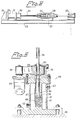
- a bench for testing rock drills comprises a beam 25, a damping device 26, which is also shown in Fig 3, a cradle 27 for a percussive rock drill 28 and a hydraulic feeding cylinder 29 coupled to the rock drill.
- the damping device 26 comprises a bracKet 30, a housing 31 screwed to the bracket 30 and a drill steel holder 32 screwed to the housing 31.
- the drill steel holder 32 comprises a rotatably journalled bushing 33 that has a hexagonal hole adapted to receive the hexagonal drill steel 34 which is cut off so that its front end is flat.
- the bushing 33 is coupled to a hydraulic rotary motor 35 by means of a belt 36.
- the housing 31 is made of steel and it has a cylinderical blind bore 37 partly filled with steel balls.
- a head 38 of a rod 39 closes a damping chamber 40 that is completely filled with steel bans.-Arcund the bore 37 there is an annular chamber 41 which has an inlet 42 and an outlet 43 for water or other coolant.
- the test bench shown in Figs 2 and 3 can be used both at the factory before delivery of the rock drills and at work shops and service centers.
- the hydraulic or pneumatic rock drill 28 that is to be tested is mounted on the cradle 27 and the drill steel 34 is inserted into the drill steel holder 32 as shown in Fig 2.
- the hammer piston 44 of the rock drill is schematically indicated in Fig 2 whereas the rotation motor of the rock drill is not illustrated.
- the hydraulic cylinder 29 is operated to apply a feed force on the rock drill 28 which is slidable along the beam 25, and the rock drill 28 is then operated to rotate the drill steel 34 and to impact upon the rear end of the drill steel.
- the hydraulic motor 35 is used to brake the rotation of the drill steel 34 and it is used for indication of the torque of the rotation motor of the rock drill.
- the heat generated by the friction between the drill steel 34 and the rod 39 is small as compared to the impact energy and comparatively corstant.
- Fig 4 shows, partly in a longitudinal section, a rock drill with a damping device for the stress waves reflected from the rock.
- the rock drill comprises a housing 50 in which a hammer piston 51 is reciprocally driven by a pressure fluid e.g. hydraulic fluid or compressed air.
- the piston 51 is arranged to periodically impact upon the rear end face 52 of a drill stem adapter 53 which has an enlarged portion 54 of non-circular ctoss section in engagement with a bushing 55 of a rotatably journalled rotation chuck 56 so that the adapter 53 can be rotated by a hydraulic or pneumatic rotary motor 57 which is coupled to the chuck 56.
- the rear end surface 58 of the enlarged portion 54 of the adapter 53 takes support against a sleeve 59.
- the sleeve 59 abuts agairst another sleeve 60 that together with a sleeve 61 forms a cylindrical annular chamber 62 that is filled with steel balls.
- a roller bearing 63 is inserted between the housing and the sleeve 61 as a thrust bearing.
- the parts 55, 56, 59, 60, 61, 62 are rotatable as a unit.
- the rock drill can be mounted on the feed beam of a rock drilling rig and the feed force applied to the rock drill by a feed motor of the feed beam or by any other means is thus transmitted from the housing 50 to the adapter 53 via the thrust bearing 63 and the ball filled chamber 62.
- the size of the balls must be sma!ler than' the width of the chambers and preferably smaller than half the width. This ensures wedging actions which would not occur if the balls were in straight lines.
- the balls can advantageously be of even size.
- Steel balls intended for ball bearings are advantageous.
- Other hard non-plastic particles can also be used.
- Steel sand intended for shot blasting can be used but it has disadvantages as compared to steel balls.
- the particles are not of even size and they have a'scale. The bulk of particles is compressed during the first,hours of use and the descaling that occurs causes dust.
Landscapes
- Engineering & Computer Science (AREA)
- Mechanical Engineering (AREA)
- General Engineering & Computer Science (AREA)
- Earth Drilling (AREA)
- Vibration Dampers (AREA)
Applications Claiming Priority (2)
| Application Number | Priority Date | Filing Date | Title |
|---|---|---|---|
| SE8102430A SE8102430L (sv) | 1981-04-15 | 1981-04-15 | Forfarande och anordning for att dempa stotvagor |
| SE8102430 | 1981-04-15 |
Publications (1)
| Publication Number | Publication Date |
|---|---|
| EP0064038A1 true EP0064038A1 (fr) | 1982-11-03 |
Family
ID=20343607
Family Applications (1)
| Application Number | Title | Priority Date | Filing Date |
|---|---|---|---|
| EP82850060A Withdrawn EP0064038A1 (fr) | 1981-04-15 | 1982-03-24 | Procédé et dispositif pour amortir des ondes compressives |
Country Status (7)
| Country | Link |
|---|---|
| EP (1) | EP0064038A1 (fr) |
| JP (1) | JPS57184739A (fr) |
| AU (1) | AU8263682A (fr) |
| FI (1) | FI821236L (fr) |
| NO (1) | NO821024L (fr) |
| SE (1) | SE8102430L (fr) |
| ZA (1) | ZA821976B (fr) |
Cited By (2)
| Publication number | Priority date | Publication date | Assignee | Title |
|---|---|---|---|---|
| EP0156387A3 (en) * | 1984-03-30 | 1987-05-20 | Makoto Minamidate | Vibration-proof grip device |
| EP2199031A4 (fr) * | 2007-09-13 | 2011-11-30 | Makita Corp | Outil d'impact |
Families Citing this family (3)
| Publication number | Priority date | Publication date | Assignee | Title |
|---|---|---|---|---|
| JPH0550192U (ja) * | 1991-12-09 | 1993-07-02 | 株式会社コガネイ | ショックアブソーバ |
| JP4897512B2 (ja) * | 2007-02-23 | 2012-03-14 | 富士夫 堀 | 粉粒体混合ガス生成機 |
| CN108443325B (zh) * | 2018-04-02 | 2019-06-11 | 江苏理工学院 | 用于高速旋转机械的碰撞阻尼器 |
Citations (1)
| Publication number | Priority date | Publication date | Assignee | Title |
|---|---|---|---|---|
| DE2456090A1 (de) * | 1973-12-01 | 1975-06-05 | Af Hydraulics | Hydraulisch betaetigtes schlaggeraet |
-
1981
- 1981-04-15 SE SE8102430A patent/SE8102430L/ not_active Application Discontinuation
-
1982
- 1982-03-24 ZA ZA821976A patent/ZA821976B/xx unknown
- 1982-03-24 EP EP82850060A patent/EP0064038A1/fr not_active Withdrawn
- 1982-03-26 NO NO821024A patent/NO821024L/no unknown
- 1982-04-07 FI FI821236A patent/FI821236L/fi not_active Application Discontinuation
- 1982-04-13 JP JP57060440A patent/JPS57184739A/ja active Pending
- 1982-04-15 AU AU82636/82A patent/AU8263682A/en not_active Abandoned
Patent Citations (1)
| Publication number | Priority date | Publication date | Assignee | Title |
|---|---|---|---|---|
| DE2456090A1 (de) * | 1973-12-01 | 1975-06-05 | Af Hydraulics | Hydraulisch betaetigtes schlaggeraet |
Cited By (2)
| Publication number | Priority date | Publication date | Assignee | Title |
|---|---|---|---|---|
| EP0156387A3 (en) * | 1984-03-30 | 1987-05-20 | Makoto Minamidate | Vibration-proof grip device |
| EP2199031A4 (fr) * | 2007-09-13 | 2011-11-30 | Makita Corp | Outil d'impact |
Also Published As
| Publication number | Publication date |
|---|---|
| FI821236A7 (fi) | 1982-10-16 |
| FI821236L (fi) | 1982-10-16 |
| JPS57184739A (en) | 1982-11-13 |
| ZA821976B (en) | 1983-03-30 |
| SE8102430L (sv) | 1982-10-16 |
| FI821236A0 (fi) | 1982-04-07 |
| AU8263682A (en) | 1982-10-21 |
| NO821024L (no) | 1982-10-18 |
Similar Documents
| Publication | Publication Date | Title |
|---|---|---|
| Franca | A bit–rock interaction model for rotary–percussive drilling | |
| AU702744B2 (en) | Device for transmitting impulse-like blows to a continuously rotatable tool bit | |
| US3842942A (en) | Constrained layer damper and noise suppressor for a rock drill steel | |
| JP2005505711A5 (fr) | ||
| JP4050468B2 (ja) | 削岩機の穴あけを制御する方法と装置 | |
| US8056648B2 (en) | Method and device | |
| WO1999032266A1 (fr) | Machine d'impact | |
| Zhao et al. | Effects of working angle on pneumatic down-the-hole hammer drilling | |
| US20110094765A1 (en) | Percussive augmenter of rotary drills for operating as a rotary-hammer drill | |
| US8960325B2 (en) | Free-mass and interface configurations of hammering mechanisms | |
| US4903785A (en) | Drilling and chiseling tool bit | |
| US20170144287A1 (en) | Handheld power tool | |
| US4103747A (en) | Buffer spring for an impact tool | |
| US5337842A (en) | Drill steel | |
| US3981540A (en) | Rock breaking apparatus | |
| FI67502B (fi) | Bullerdaempande slagorgan vid med slagverkan arbetande verktygoch anordningar foer mejsling hamring och liknande | |
| Bar-Cohen et al. | The ultrasonic/sonic driller/corer (USDC) as a subsurface drill, sampler, and lab-on-a-drill for planetary exploration applications | |
| US3861494A (en) | Sound absorbing device | |
| US3090450A (en) | Impact drill | |
| Beiers | A study of noise sources in pneumatic rock drills | |
| JP5273568B2 (ja) | 孔内起振源 | |
| KR20080013901A (ko) | 착암 요소, 드릴 스트링 및 충격 에너지를 탑해머유닛으로부터 드릴 비트로 전달하는 방법 | |
| SE8102430L (sv) | Forfarande och anordning for att dempa stotvagor | |
| Unger et al. | Percussive drilling with independent rotation | |
| SU1117141A1 (ru) | Дрель |
Legal Events
| Date | Code | Title | Description |
|---|---|---|---|
| PUAI | Public reference made under article 153(3) epc to a published international application that has entered the european phase |
Free format text: ORIGINAL CODE: 0009012 |
|
| AK | Designated contracting states |
Designated state(s): AT BE CH DE FR GB IT |
|
| 17P | Request for examination filed |
Effective date: 19830407 |
|
| STAA | Information on the status of an ep patent application or granted ep patent |
Free format text: STATUS: THE APPLICATION HAS BEEN WITHDRAWN |
|
| 18W | Application withdrawn |
Withdrawal date: 19840119 |
|
| RIN1 | Information on inventor provided before grant (corrected) |
Inventor name: WIJK, AXEL GUNNAR |