EP0064087B1 - Auftastsicheres Zylinderschloss - Google Patents
Auftastsicheres Zylinderschloss Download PDFInfo
- Publication number
- EP0064087B1 EP0064087B1 EP81103287A EP81103287A EP0064087B1 EP 0064087 B1 EP0064087 B1 EP 0064087B1 EP 81103287 A EP81103287 A EP 81103287A EP 81103287 A EP81103287 A EP 81103287A EP 0064087 B1 EP0064087 B1 EP 0064087B1
- Authority
- EP
- European Patent Office
- Prior art keywords
- lock
- key
- cylinder
- locking means
- ward
- Prior art date
- Legal status (The legal status is an assumption and is not a legal conclusion. Google has not performed a legal analysis and makes no representation as to the accuracy of the status listed.)
- Expired
Links
- 235000014676 Phragmites communis Nutrition 0.000 claims description 3
- 230000000717 retained effect Effects 0.000 claims description 3
- 230000000694 effects Effects 0.000 claims description 2
- 230000007246 mechanism Effects 0.000 abstract 1
- 238000004519 manufacturing process Methods 0.000 description 4
- 238000012986 modification Methods 0.000 description 2
- 230000004048 modification Effects 0.000 description 2
- 244000089486 Phragmites australis subsp australis Species 0.000 description 1
- 238000009825 accumulation Methods 0.000 description 1
- 230000000295 complement effect Effects 0.000 description 1
- 238000010276 construction Methods 0.000 description 1
- 230000007547 defect Effects 0.000 description 1
- 230000002708 enhancing effect Effects 0.000 description 1
- JEIPFZHSYJVQDO-UHFFFAOYSA-N iron(III) oxide Inorganic materials O=[Fe]O[Fe]=O JEIPFZHSYJVQDO-UHFFFAOYSA-N 0.000 description 1
- 230000013011 mating Effects 0.000 description 1
- 239000002184 metal Substances 0.000 description 1
- 238000003466 welding Methods 0.000 description 1
Images

Classifications
-
- E—FIXED CONSTRUCTIONS
- E05—LOCKS; KEYS; WINDOW OR DOOR FITTINGS; SAFES
- E05B—LOCKS; ACCESSORIES THEREFOR; HANDCUFFS
- E05B35/00—Locks for use with special keys or a plurality of keys ; keys therefor
Definitions
- the present invention concerns a cylinder lock and a key for unlocking this lock, comprising a body with a hook, and locking means to prevent the hook from being pulled out from locked position to unlocked position; a rotatable cylinder with its upper end structured so as to co-operate with the locking means to allow the hook to be pulled out when the cylinder is turned to a certain position; a bush with one of its ends forming a tortuous entrance into which the key can be screwed, said bush being fixedly secured in the body.
- conventional cylinder keys comprise substantially a planar key with an indented edge, a cylinder, and a body internally provided with a plurality of pin tumblers resiliently retained in a tunnel orienting to the keyway.
- the resilient means generally springs, which urge the pin tumblers against the notches of a key at a specific level to discriminate if the key is the correct one, are hair-spring thin. After some use accumulation of rust or dirt may lead to failure of such fine parts, thus reducing the life of the lock.
- a preferred feature of this invention is that the resilient means can be economically a thick metal reeds instead of the springs fabricated by extremely fine wire, thus enhancing the durability and reducing the cost of the manufacture thereof.
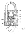
- the cylinder lock according to the invention includes a body, a cylinder, a bush and a key, generally designated by reference numerals (10), (20), (30), and (40) respectively.
- the body has a bore (11) which receives cylinder (20) and bush (30), the former being rotatable therein, whereas the latter being immovably secured in place, for example by passing a pin (15) through hole (151).
- Hook (12) has a recess (121), the dimension and the position of which allow one part of ball (13) retained within a hole (14) to enter when the hook is in locked position in blind hole (16) so that it cannot be pull up.
- Like structure may be formed at the other leg of hook (12). (See Figure 2).
- cylinder (20) At one end of cylinder (20) there are provided with two opposite recesses (26), each of which is formed by a cutout defined by two intersecting faces (261) (262).
- face (261) directly opposite to ball (13), i.e. normal to the long axis of hole (14) the clearance between the inner wall of body (10) and the upper end of cylinder is broadest and enough to allow the ball to totally leave recess (121) to free hook (12) so that the latter can be unlocked (see Figure 2).
- the non-recessed portion (27) urges ball (13) back into recess (121) to lock hook (12).
- the outer end of bush (30) is provided with a spiral entrance (31) which is structured so that only an object with spiral structure of which the pitch and lead angle substantially coincides with that of the entrance is allowed to be screwed thereinto. Further, to discriminate whether or not the key thus enters is the correct one, the lower end (21) of cylinder (20), which is nested in the upper end of bush (30), forms a plurality of slots (22) spaced apart from each other around the periphery of end (21) and extending along the length of cylinder (20).
- the end of key (40) forms an enlarged end (42) provided with a plurality of projectors (41) arranged around the periphery thereof, the dimension and position of which projections substantially coincide with the slots (22), and at the site the upper end of bush corresponding to each slot (22) there is a hole (32), through which a ward piece (33) is resiliently urged inwardly to reach one of said slots (22).
- the projections are preferably ridged extending along the length of said key.
- ward piece (33) is inseparably fixed to one end of a spring reed (34), the other end of the latter being secured to the outer wall of bush (30) by, for example, welding or by a screw (not shown).
- spiral groove (43) extending across the projections (41), which spiral groove (43) is bitten into by the helical edge (31 1 ) of spiral entrance (31), thereby allowing the key to be screwed into the bush to reach cylinder.
- the enlarged end (42) of the key looks like a gear.
- the width of each projection and the distance between any two adjacent projections may differ greatly at random, depending on the design of the slots (22). As all of the pitch and the lead angle of the spiral entrance, and the position and number of the slots may vary arbitrarily, the probability that a lock happened to be unlocked by the key of another such lock is extremely low, thus ensuring high security and reliability of this invention.
- An alternative modification of the key (40), designated by (40'), is also feasible. It has a spiral shank (43'), with a length of its front forming a plurality of projections at the outer side.
- the slots (22) of cylinder (20) and the ward pieces (33) and holes (32) of bush (30) must be arranged in a spiral trajectory instead of a circumference. This is easy to understand, and therefore not illustrated in the drawing.
- the spiral shank must be structured so that it, before reaching the slots, can be pushed inwardly a short distance in axial direction to fit its projection into mating slots.
Landscapes
- Lock And Its Accessories (AREA)
- Centrifugal Separators (AREA)
- Control And Other Processes For Unpacking Of Materials (AREA)
- Processing Of Solid Wastes (AREA)
- Refuge Islands, Traffic Blockers, Or Guard Fence (AREA)
- Gates (AREA)
Claims (12)
Priority Applications (3)
| Application Number | Priority Date | Filing Date | Title |
|---|---|---|---|
| AT81103287T ATE11317T1 (de) | 1981-04-30 | 1981-04-30 | Auftastsicheres zylinderschloss. |
| DE8181103287T DE3168256D1 (en) | 1981-04-30 | 1981-04-30 | Cylinder lock resistant to picking |
| EP81103287A EP0064087B1 (de) | 1981-04-30 | 1981-04-30 | Auftastsicheres Zylinderschloss |
Applications Claiming Priority (1)
| Application Number | Priority Date | Filing Date | Title |
|---|---|---|---|
| EP81103287A EP0064087B1 (de) | 1981-04-30 | 1981-04-30 | Auftastsicheres Zylinderschloss |
Publications (2)
| Publication Number | Publication Date |
|---|---|
| EP0064087A1 EP0064087A1 (de) | 1982-11-10 |
| EP0064087B1 true EP0064087B1 (de) | 1985-01-16 |
Family
ID=8187693
Family Applications (1)
| Application Number | Title | Priority Date | Filing Date |
|---|---|---|---|
| EP81103287A Expired EP0064087B1 (de) | 1981-04-30 | 1981-04-30 | Auftastsicheres Zylinderschloss |
Country Status (3)
| Country | Link |
|---|---|
| EP (1) | EP0064087B1 (de) |
| AT (1) | ATE11317T1 (de) |
| DE (1) | DE3168256D1 (de) |
Cited By (1)
| Publication number | Priority date | Publication date | Assignee | Title |
|---|---|---|---|---|
| EP0189147A1 (de) * | 1985-01-18 | 1986-07-30 | John F. Masoncup | Vorlegeschloss mit hörbarer und/oder nicht hörbarer Alarmvorrichtung, welche durch einen Stössel ausgelöst wird |
Families Citing this family (1)
| Publication number | Priority date | Publication date | Assignee | Title |
|---|---|---|---|---|
| WO2007030942A1 (en) * | 2005-09-15 | 2007-03-22 | Pinhead Components Inc. | Locking system with hidden keyed access |
Family Cites Families (7)
| Publication number | Priority date | Publication date | Assignee | Title |
|---|---|---|---|---|
| DE179910C (de) * | ||||
| DE593541C (de) * | 1934-02-28 | Emil Gross | Schluessel fuer Sicherheitsschloesser | |
| US1526728A (en) * | 1923-11-23 | 1925-02-17 | Wagner Julius Stanley | Lock |
| US1849070A (en) * | 1928-10-15 | 1932-03-15 | Buehner Christian | Padlock |
| US2460551A (en) * | 1945-06-16 | 1949-02-01 | Gunnar E Swanson | Unitary tumbler cylinder lock |
| US3320783A (en) * | 1966-12-09 | 1967-05-23 | Chicago Lock Co | Key for an axial tumbler type lock |
| US4138868A (en) * | 1977-08-19 | 1979-02-13 | Richards Sr Frederick F | Replaceable cylinder padlock |
-
1981
- 1981-04-30 DE DE8181103287T patent/DE3168256D1/de not_active Expired
- 1981-04-30 AT AT81103287T patent/ATE11317T1/de not_active IP Right Cessation
- 1981-04-30 EP EP81103287A patent/EP0064087B1/de not_active Expired
Cited By (1)
| Publication number | Priority date | Publication date | Assignee | Title |
|---|---|---|---|---|
| EP0189147A1 (de) * | 1985-01-18 | 1986-07-30 | John F. Masoncup | Vorlegeschloss mit hörbarer und/oder nicht hörbarer Alarmvorrichtung, welche durch einen Stössel ausgelöst wird |
Also Published As
| Publication number | Publication date |
|---|---|
| EP0064087A1 (de) | 1982-11-10 |
| DE3168256D1 (en) | 1985-02-28 |
| ATE11317T1 (de) | 1985-02-15 |
Similar Documents
| Publication | Publication Date | Title |
|---|---|---|
| US6508091B1 (en) | Cylinder lock with effraction-resistant device | |
| US4941336A (en) | Lock mechanism | |
| US4823575A (en) | Cylinder lock and key | |
| US3990282A (en) | Tumbler type lock | |
| US4393673A (en) | Cylinder lock | |
| US4672827A (en) | Disc tumbler lock with removable plug | |
| US4377940A (en) | Impression-resistant lock | |
| US4512166A (en) | Cylinder lock and key | |
| US4235086A (en) | Pin tumbler lock | |
| KR0171450B1 (ko) | 보조자물쇠 | |
| EP0202949A2 (de) | Schloss und Schlüssel | |
| US3479849A (en) | Pin tumbler side bar cylinder lock | |
| CA2097002C (en) | Pin tumbler locks and keys therefor | |
| US10570643B2 (en) | Cylinder lock core for a cylinder lock unit | |
| US4770014A (en) | Lock | |
| CA1224639A (en) | Cylinder locks | |
| US4858456A (en) | Resettable axial tumbler lock | |
| US4953373A (en) | Key removable core body | |
| EP0064087A1 (de) | Auftastsicheres Zylinderschloss | |
| US5893285A (en) | Lock cylinder | |
| US2729092A (en) | Plug and cylinder type lock mechanism | |
| US3505837A (en) | Padlock picking guard and driver spacer | |
| US20200378151A1 (en) | Lock and key therefor | |
| US4619124A (en) | Cylinder lock with anti-picking device | |
| GB2358670A (en) | Key and cylinder lock |
Legal Events
| Date | Code | Title | Description |
|---|---|---|---|
| PUAI | Public reference made under article 153(3) epc to a published international application that has entered the european phase |
Free format text: ORIGINAL CODE: 0009012 |
|
| 17P | Request for examination filed |
Effective date: 19820416 |
|
| AK | Designated contracting states |
Designated state(s): AT BE CH DE FR GB IT LU NL SE |
|
| RBV | Designated contracting states (corrected) |
Designated state(s): AT BE CH DE FR IT LI LU NL SE |
|
| ITF | It: translation for a ep patent filed | ||
| GRAA | (expected) grant |
Free format text: ORIGINAL CODE: 0009210 |
|
| AK | Designated contracting states |
Designated state(s): AT BE CH DE FR IT LI LU NL SE |
|
| REF | Corresponds to: |
Ref document number: 11317 Country of ref document: AT Date of ref document: 19850215 Kind code of ref document: T |
|
| REF | Corresponds to: |
Ref document number: 3168256 Country of ref document: DE Date of ref document: 19850228 |
|
| ET | Fr: translation filed | ||
| PG25 | Lapsed in a contracting state [announced via postgrant information from national office to epo] |
Ref country code: LU Free format text: LAPSE BECAUSE OF NON-PAYMENT OF DUE FEES Effective date: 19850430 |
|
| PLBE | No opposition filed within time limit |
Free format text: ORIGINAL CODE: 0009261 |
|
| STAA | Information on the status of an ep patent application or granted ep patent |
Free format text: STATUS: NO OPPOSITION FILED WITHIN TIME LIMIT |
|
| 26N | No opposition filed | ||
| PGFP | Annual fee paid to national office [announced via postgrant information from national office to epo] |
Ref country code: AT Payment date: 19860430 Year of fee payment: 6 |
|
| PGFP | Annual fee paid to national office [announced via postgrant information from national office to epo] |
Ref country code: NL Payment date: 19870430 Year of fee payment: 7 |
|
| PG25 | Lapsed in a contracting state [announced via postgrant information from national office to epo] |
Ref country code: LI Effective date: 19890430 Ref country code: CH Effective date: 19890430 Ref country code: BE Effective date: 19890430 Ref country code: AT Effective date: 19890430 |
|
| PG25 | Lapsed in a contracting state [announced via postgrant information from national office to epo] |
Ref country code: SE Effective date: 19890501 |
|
| BERE | Be: lapsed |
Owner name: HUANG TSAO-KENG Effective date: 19890430 |
|
| PG25 | Lapsed in a contracting state [announced via postgrant information from national office to epo] |
Ref country code: NL Effective date: 19891101 |
|
| NLV4 | Nl: lapsed or anulled due to non-payment of the annual fee | ||
| PG25 | Lapsed in a contracting state [announced via postgrant information from national office to epo] |
Ref country code: FR Free format text: LAPSE BECAUSE OF NON-PAYMENT OF DUE FEES Effective date: 19891228 |
|
| REG | Reference to a national code |
Ref country code: CH Ref legal event code: PL |
|
| PG25 | Lapsed in a contracting state [announced via postgrant information from national office to epo] |
Ref country code: DE Effective date: 19900103 |
|
| REG | Reference to a national code |
Ref country code: FR Ref legal event code: ST |
|
| EUG | Se: european patent has lapsed |
Ref document number: 81103287.9 Effective date: 19900412 |