EP0064089B1 - Dispositif pour la gazéification sous pression de poussier de charbon - Google Patents
Dispositif pour la gazéification sous pression de poussier de charbon Download PDFInfo
- Publication number
- EP0064089B1 EP0064089B1 EP81103343A EP81103343A EP0064089B1 EP 0064089 B1 EP0064089 B1 EP 0064089B1 EP 81103343 A EP81103343 A EP 81103343A EP 81103343 A EP81103343 A EP 81103343A EP 0064089 B1 EP0064089 B1 EP 0064089B1
- Authority
- EP
- European Patent Office
- Prior art keywords
- reactor
- coal dust
- gasification
- slag
- coal
- Prior art date
- Legal status (The legal status is an assumption and is not a legal conclusion. Google has not performed a legal analysis and makes no representation as to the accuracy of the status listed.)
- Expired
Links
- 239000002817 coal dust Substances 0.000 title claims abstract description 29
- 238000002309 gasification Methods 0.000 title claims abstract description 25
- 239000007788 liquid Substances 0.000 claims abstract description 6
- 239000000203 mixture Substances 0.000 claims abstract description 4
- 239000002253 acid Substances 0.000 claims abstract 3
- 239000002826 coolant Substances 0.000 claims description 4
- 238000001816 cooling Methods 0.000 claims description 3
- 238000006243 chemical reaction Methods 0.000 description 20
- 239000002893 slag Substances 0.000 description 19
- OKTJSMMVPCPJKN-UHFFFAOYSA-N Carbon Chemical compound [C] OKTJSMMVPCPJKN-UHFFFAOYSA-N 0.000 description 15
- 229910052799 carbon Inorganic materials 0.000 description 15
- 239000002245 particle Substances 0.000 description 15
- 239000007789 gas Substances 0.000 description 14
- 239000003795 chemical substances by application Substances 0.000 description 8
- QVGXLLKOCUKJST-UHFFFAOYSA-N atomic oxygen Chemical compound [O] QVGXLLKOCUKJST-UHFFFAOYSA-N 0.000 description 7
- 229910052760 oxygen Inorganic materials 0.000 description 7
- 239000001301 oxygen Substances 0.000 description 7
- 239000007787 solid Substances 0.000 description 5
- 239000007900 aqueous suspension Substances 0.000 description 4
- 239000003245 coal Substances 0.000 description 4
- 239000000725 suspension Substances 0.000 description 4
- 230000000694 effects Effects 0.000 description 3
- 238000010438 heat treatment Methods 0.000 description 3
- 238000000034 method Methods 0.000 description 3
- 229910000831 Steel Inorganic materials 0.000 description 2
- 238000000889 atomisation Methods 0.000 description 2
- 238000001035 drying Methods 0.000 description 2
- 239000010959 steel Substances 0.000 description 2
- XLYOFNOQVPJJNP-UHFFFAOYSA-N water Chemical compound O XLYOFNOQVPJJNP-UHFFFAOYSA-N 0.000 description 2
- 238000007664 blowing Methods 0.000 description 1
- POIUWJQBRNEFGX-XAMSXPGMSA-N cathelicidin Chemical compound C([C@@H](C(=O)N[C@@H](CCCNC(N)=N)C(=O)N[C@@H](CCCCN)C(=O)N[C@@H](CO)C(=O)N[C@@H](CCCCN)C(=O)N[C@@H](CCC(O)=O)C(=O)N[C@@H](CCCCN)C(=O)N[C@@H]([C@@H](C)CC)C(=O)NCC(=O)N[C@@H](CCCCN)C(=O)N[C@@H](CCC(O)=O)C(=O)N[C@@H](CC=1C=CC=CC=1)C(=O)N[C@@H](CCCCN)C(=O)N[C@@H](CCCNC(N)=N)C(=O)N[C@@H]([C@@H](C)CC)C(=O)N[C@@H](C(C)C)C(=O)N[C@@H](CCC(N)=O)C(=O)N[C@@H](CCCNC(N)=N)C(=O)N[C@@H]([C@@H](C)CC)C(=O)N[C@@H](CCCCN)C(=O)N[C@@H](CC(O)=O)C(=O)N[C@@H](CC=1C=CC=CC=1)C(=O)N[C@@H](CC(C)C)C(=O)N[C@@H](CCCNC(N)=N)C(=O)N[C@@H](CC(N)=O)C(=O)N[C@@H](CC(C)C)C(=O)N[C@@H](C(C)C)C(=O)N1[C@@H](CCC1)C(=O)N[C@@H](CCCNC(N)=N)C(=O)N[C@@H]([C@@H](C)O)C(=O)N[C@@H](CCC(O)=O)C(=O)N[C@@H](CO)C(O)=O)NC(=O)[C@H](CC=1C=CC=CC=1)NC(=O)[C@H](CC(O)=O)NC(=O)CNC(=O)[C@H](CC(C)C)NC(=O)[C@@H](N)CC(C)C)C1=CC=CC=C1 POIUWJQBRNEFGX-XAMSXPGMSA-N 0.000 description 1
- 238000002485 combustion reaction Methods 0.000 description 1
- 238000010276 construction Methods 0.000 description 1
- 239000000428 dust Substances 0.000 description 1
- 230000009970 fire resistant effect Effects 0.000 description 1
- 230000009969 flowable effect Effects 0.000 description 1
- 238000000227 grinding Methods 0.000 description 1
- 229910052500 inorganic mineral Inorganic materials 0.000 description 1
- 238000009434 installation Methods 0.000 description 1
- 239000000463 material Substances 0.000 description 1
- 239000011707 mineral Substances 0.000 description 1
- 230000000717 retained effect Effects 0.000 description 1
- 239000000126 substance Substances 0.000 description 1
- 230000007306 turnover Effects 0.000 description 1
Images
Classifications
-
- C—CHEMISTRY; METALLURGY
- C10—PETROLEUM, GAS OR COKE INDUSTRIES; TECHNICAL GASES CONTAINING CARBON MONOXIDE; FUELS; LUBRICANTS; PEAT
- C10J—PRODUCTION OF PRODUCER GAS, WATER-GAS, SYNTHESIS GAS FROM SOLID CARBONACEOUS MATERIAL, OR MIXTURES CONTAINING THESE GASES; CARBURETTING AIR OR OTHER GASES
- C10J3/00—Production of combustible gases containing carbon monoxide from solid carbonaceous fuels
- C10J3/46—Gasification of granular or pulverulent flues in suspension
- C10J3/48—Apparatus; Plants
- C10J3/485—Entrained flow gasifiers
-
- C—CHEMISTRY; METALLURGY
- C10—PETROLEUM, GAS OR COKE INDUSTRIES; TECHNICAL GASES CONTAINING CARBON MONOXIDE; FUELS; LUBRICANTS; PEAT
- C10J—PRODUCTION OF PRODUCER GAS, WATER-GAS, SYNTHESIS GAS FROM SOLID CARBONACEOUS MATERIAL, OR MIXTURES CONTAINING THESE GASES; CARBURETTING AIR OR OTHER GASES
- C10J3/00—Production of combustible gases containing carbon monoxide from solid carbonaceous fuels
- C10J3/46—Gasification of granular or pulverulent flues in suspension
- C10J3/48—Apparatus; Plants
- C10J3/52—Ash-removing devices
- C10J3/526—Ash-removing devices for entrained flow gasifiers
-
- C—CHEMISTRY; METALLURGY
- C10—PETROLEUM, GAS OR COKE INDUSTRIES; TECHNICAL GASES CONTAINING CARBON MONOXIDE; FUELS; LUBRICANTS; PEAT
- C10J—PRODUCTION OF PRODUCER GAS, WATER-GAS, SYNTHESIS GAS FROM SOLID CARBONACEOUS MATERIAL, OR MIXTURES CONTAINING THESE GASES; CARBURETTING AIR OR OTHER GASES
- C10J3/00—Production of combustible gases containing carbon monoxide from solid carbonaceous fuels
- C10J3/72—Other features
- C10J3/74—Construction of shells or jackets
-
- C—CHEMISTRY; METALLURGY
- C10—PETROLEUM, GAS OR COKE INDUSTRIES; TECHNICAL GASES CONTAINING CARBON MONOXIDE; FUELS; LUBRICANTS; PEAT
- C10J—PRODUCTION OF PRODUCER GAS, WATER-GAS, SYNTHESIS GAS FROM SOLID CARBONACEOUS MATERIAL, OR MIXTURES CONTAINING THESE GASES; CARBURETTING AIR OR OTHER GASES
- C10J3/00—Production of combustible gases containing carbon monoxide from solid carbonaceous fuels
- C10J3/72—Other features
- C10J3/74—Construction of shells or jackets
- C10J3/76—Water jackets; Steam boiler-jackets
-
- C—CHEMISTRY; METALLURGY
- C10—PETROLEUM, GAS OR COKE INDUSTRIES; TECHNICAL GASES CONTAINING CARBON MONOXIDE; FUELS; LUBRICANTS; PEAT
- C10J—PRODUCTION OF PRODUCER GAS, WATER-GAS, SYNTHESIS GAS FROM SOLID CARBONACEOUS MATERIAL, OR MIXTURES CONTAINING THESE GASES; CARBURETTING AIR OR OTHER GASES
- C10J3/00—Production of combustible gases containing carbon monoxide from solid carbonaceous fuels
- C10J3/72—Other features
- C10J3/78—High-pressure apparatus
-
- C—CHEMISTRY; METALLURGY
- C10—PETROLEUM, GAS OR COKE INDUSTRIES; TECHNICAL GASES CONTAINING CARBON MONOXIDE; FUELS; LUBRICANTS; PEAT
- C10J—PRODUCTION OF PRODUCER GAS, WATER-GAS, SYNTHESIS GAS FROM SOLID CARBONACEOUS MATERIAL, OR MIXTURES CONTAINING THESE GASES; CARBURETTING AIR OR OTHER GASES
- C10J2300/00—Details of gasification processes
- C10J2300/09—Details of the feed, e.g. feeding of spent catalyst, inert gas or halogens
- C10J2300/0913—Carbonaceous raw material
- C10J2300/093—Coal
-
- C—CHEMISTRY; METALLURGY
- C10—PETROLEUM, GAS OR COKE INDUSTRIES; TECHNICAL GASES CONTAINING CARBON MONOXIDE; FUELS; LUBRICANTS; PEAT
- C10J—PRODUCTION OF PRODUCER GAS, WATER-GAS, SYNTHESIS GAS FROM SOLID CARBONACEOUS MATERIAL, OR MIXTURES CONTAINING THESE GASES; CARBURETTING AIR OR OTHER GASES
- C10J2300/00—Details of gasification processes
- C10J2300/09—Details of the feed, e.g. feeding of spent catalyst, inert gas or halogens
- C10J2300/0953—Gasifying agents
- C10J2300/0956—Air or oxygen enriched air
-
- C—CHEMISTRY; METALLURGY
- C10—PETROLEUM, GAS OR COKE INDUSTRIES; TECHNICAL GASES CONTAINING CARBON MONOXIDE; FUELS; LUBRICANTS; PEAT
- C10J—PRODUCTION OF PRODUCER GAS, WATER-GAS, SYNTHESIS GAS FROM SOLID CARBONACEOUS MATERIAL, OR MIXTURES CONTAINING THESE GASES; CARBURETTING AIR OR OTHER GASES
- C10J2300/00—Details of gasification processes
- C10J2300/09—Details of the feed, e.g. feeding of spent catalyst, inert gas or halogens
- C10J2300/0953—Gasifying agents
- C10J2300/0959—Oxygen
-
- C—CHEMISTRY; METALLURGY
- C10—PETROLEUM, GAS OR COKE INDUSTRIES; TECHNICAL GASES CONTAINING CARBON MONOXIDE; FUELS; LUBRICANTS; PEAT
- C10J—PRODUCTION OF PRODUCER GAS, WATER-GAS, SYNTHESIS GAS FROM SOLID CARBONACEOUS MATERIAL, OR MIXTURES CONTAINING THESE GASES; CARBURETTING AIR OR OTHER GASES
- C10J2300/00—Details of gasification processes
- C10J2300/09—Details of the feed, e.g. feeding of spent catalyst, inert gas or halogens
- C10J2300/0953—Gasifying agents
- C10J2300/0973—Water
- C10J2300/0976—Water as steam
Definitions
- the invention relates to a device for coal dust pressure gasification in which the coal dust and / or a coal dust / liquid mixture is blown into a reactor and gasified in the presence of steam and oxygen to form a CO and H 2 -containing gas, and at least at the discharge end of the reactor a slag film is generated.
- Gasification in the slag bath is known.
- the coal dust with the gasification agent is blown obliquely from above onto a liquid slag melt.
- the solid particles which are specifically lighter than the slag, are deposited on the surface of the bath and float on the surface until only the molten ash portion remains.
- the slag is drawn down over an overflow of the bath. The gas leaves the reactor upwards.
- the very long residence time of the solid ensures almost complete carbon conversion. Lower degrees of fineness of the carbon carrier are sufficient for this and an exactly constant dosage is not necessary.
- the reactor temperature should be set so that the flow behavior of the slag allows turbulent movement of the slag bath.
- the simple structure of the reactor ensures trouble-free operation, but in order to achieve constant operating conditions, an absolutely constant use of coal and gasification agent is required. In order to reduce the necessary dwell time of the solid particles, very fine grinding of the coal is also imperative.
- the present invention has for its object to improve the carbon conversion in coal dust gasification while maintaining or increasing the economy.
- the invention is based on the fact that the residence time of the solid should be independent of the residence time of the gas, as is the case in the slag bath generator. At the same time, however, the simple operation of the entrained-flow gasifier should be retained as far as possible.
- a sufficient residence time is achieved without the disadvantages of DE-B-1 091 268 in that the usual routing of the coal dust / liquid / gas mixture is maintained and the reactor is provided at the discharge end with a flow control device which is table-shaped.
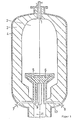
- a burner 1 turns a rotationally symmetrical reactor space 2 into a solid carbon carrier, e.g. Coal dust, supplied in dry or suspended form.
- the necessary gasification agent e.g. Oxygen and water vapor into the reactor interior 2.
- the reactor interior is surrounded by a refractory lining 3, which, as shown in FIG. 1, is only cooled by the heat given off by a steel jacket 4, or has forced cooling, not shown, within the steel jacket 4 .
- the oxygen portion of the gasification agent converts with the combustible portions of the gas atmosphere in the reactor interior 2 in a flame.
- the coal dust is brought to the reaction temperature by absorbing heat from the environment, the mean temperature of which is above the slag flow point, that is, depending on the type of coal, above approximately 1350 ° C.
- the coal dust is introduced in the form e.g. a coal-water suspension, the suspension drops produced on the burner 1 by atomization are still dried before heating to the reaction temperature.
- the temperature difference between the carbon particles and the surrounding gas atmosphere is large, so that the heat flow necessary for the gasification reactions is guaranteed.
- the temperature difference becomes smaller because the surrounding gas atmosphere changes in accordance with the heat cooling consumption of the reaction.
- the carbon conversion rates per unit of time become lower and lower the further the reaction progresses, since the partial pressure reduction in the gasification agent also has the same effect.
- a built-in flow guide device 5 has the effect that some of the coal dust particles settle directly on the surface of this flow guide device and the remaining coal dust particles are separated on the refractory lining 3 by sharp deflection of the gas flow.
- a built-in flow guide device 5 has the effect that some of the coal dust particles settle directly on the surface of this flow guide device and the remaining coal dust particles are separated on the refractory lining 3 by sharp deflection of the gas flows.
- the flow guide device 5 is designed here in the form of a round table.
- the table top consists of several spirally wound, pinned tubes 6, which are clad with a refractory mass.
- a cooling medium flows through the tubes 6, which enters at 7 and exits at 8.
- the four feed and discharge pipes 9, 10 in total also pinned and clad with a fire-resistant mass. They also serve as a supporting structure for the table top.
- the resulting slag film runs on the wall of the reactor neck 11 and arrives in a water bath (not shown), where the slag is granulated and discharged via a lock device.
- the gas generated also leaves the reactor through the reactor neck 11 and is subsequently cleaned or fed to any use.
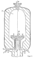
- the slag film reactor according to the invention according to FIG. 2 is particularly suitable for the gasification of coal dust which is introduced into the reactor as a coal-water suspension. This prevents the drying and heating of the coal dust particles in the area of the highest temperature within the gasification reactor, namely in the area of gas combustion with the oxygen, while the gasification reaction takes place in the coldest part of the reactor. Rather, the gasification reaction in the high temperature region of the reactor is initiated with the advantage of a particularly intensive reaction, while the drying and heating of the carbon particles takes place at low but sufficient temperatures.
- the reactor parts which are identical in FIG. 2 to FIG. 1 have the same designations.
- a pumpable coal-water suspension enters the reactor interior 2.
- the pressure of the suspension is destroyed.
- This atomization is optionally carried out by additional atomizing medium, e.g. Steam, supported.
- the suspension drops are first dried and preheated by heat transfer from the backflow of hot gas from the gasification zone before they reach the actual reaction zone at the highest temperature.
- the reaction zone is located in the lower reactor area, in which a flow control device 12 similar to the flow control device 5 is located.
- the flow guide device 12 is designed in the same way as the flow guide device 5 in the form of a round, centrally arranged table which is provided with tubes 6 and is held by the feed lines 9 and discharge lines 10.
- a line 14 for oxygen or air is passed through one of the supply lines 9.
- the line 14 is connected to an air or oxygen supply line via a connecting piece 13 and leads to a nozzle 15 at the other end.
- the nozzle 15 projects centrally through the flow guide device 12 into the reactor interior 2. It is equipped with a cap 18 to prevent clogging by slag particles protected.
- the line 14 is cooled by the cooling medium flowing into the tubes 6.
- the oxygen entering the reactor interior 2 through the nozzle 15 reacts in a flame with combustible gas formed in the reactor and with dried and preheated coal dust. This results in a particularly high and advantageous reaction temperature in the area of the flow guide device 12 in the lower reactor part.
- the remaining reaction sequences are the same as those described in the description of FIG. 1.
Landscapes
- Chemical & Material Sciences (AREA)
- Engineering & Computer Science (AREA)
- Combustion & Propulsion (AREA)
- Oil, Petroleum & Natural Gas (AREA)
- Organic Chemistry (AREA)
- Industrial Gases (AREA)
Claims (4)
Priority Applications (2)
| Application Number | Priority Date | Filing Date | Title |
|---|---|---|---|
| AT81103343T ATE10645T1 (de) | 1981-05-04 | 1981-05-04 | Vorrichtung zur kohlenstaub-druckvergasung. |
| EP81103343A EP0064089B1 (fr) | 1981-05-04 | 1981-05-04 | Dispositif pour la gazéification sous pression de poussier de charbon |
Applications Claiming Priority (1)
| Application Number | Priority Date | Filing Date | Title |
|---|---|---|---|
| EP81103343A EP0064089B1 (fr) | 1981-05-04 | 1981-05-04 | Dispositif pour la gazéification sous pression de poussier de charbon |
Publications (2)
| Publication Number | Publication Date |
|---|---|
| EP0064089A1 EP0064089A1 (fr) | 1982-11-10 |
| EP0064089B1 true EP0064089B1 (fr) | 1984-12-05 |
Family
ID=8187696
Family Applications (1)
| Application Number | Title | Priority Date | Filing Date |
|---|---|---|---|
| EP81103343A Expired EP0064089B1 (fr) | 1981-05-04 | 1981-05-04 | Dispositif pour la gazéification sous pression de poussier de charbon |
Country Status (2)
| Country | Link |
|---|---|
| EP (1) | EP0064089B1 (fr) |
| AT (1) | ATE10645T1 (fr) |
Families Citing this family (2)
| Publication number | Priority date | Publication date | Assignee | Title |
|---|---|---|---|---|
| GB8828339D0 (en) * | 1988-12-05 | 1989-01-05 | Shell Int Research | Constant volume tubular reactor |
| CN107033972A (zh) * | 2017-05-09 | 2017-08-11 | 哈尔滨工业大学 | 一种带有吹扫气保护的干煤粉气流床气化炉烧嘴 |
Family Cites Families (11)
| Publication number | Priority date | Publication date | Assignee | Title |
|---|---|---|---|---|
| DE1250046B (fr) * | 1967-09-14 | |||
| DE885766C (de) * | 1942-01-18 | 1953-08-06 | Koppers Gmbh Heinrich | Einrichtung zur Vergasung staubfoermiger oder feinkoerniger Brennstoffe |
| US2681852A (en) * | 1948-05-28 | 1954-06-22 | Texas Co | Method for partial combustion of carbonaceous materials |
| DE1091268B (de) * | 1953-09-29 | 1960-10-20 | Texaco Development Corp | Einrichtung zur Erzeugung eines Brenngases durch Vergasen eines festen feinzerteilten Brennstoffes |
| FR1207478A (fr) * | 1958-06-20 | 1960-02-17 | Sumitomo Chemical Co | Procédé de gazéification de charbon pulvérisé |
| FR1314303A (fr) * | 1962-02-09 | 1963-01-04 | Koppers Gmbh Heinrich | Procédé et dispositif pour la gazéification de poussier de charbon en suspension |
| US3607156A (en) * | 1968-12-26 | 1971-09-21 | Texaco Inc | Hydrogen and carbon monoxide from slurries of solid carboniferous fuels |
| DE2044310C3 (de) * | 1970-09-08 | 1974-01-31 | Texaco Development Corp., New York, N.Y. (V.St.A.) | Verfahren zur Herstellung von Kohlenmonoxid und Wasserstoff aus festem Brennstoff |
| DE2411086A1 (de) * | 1974-03-08 | 1975-09-18 | Koppers Gmbh Heinrich | Verfahren und vorrichtung zur verbesserung des kohlenstoff-vergasungsgrades bei der vergasung von kohlenstaub in der schwebe |
| US3988123A (en) * | 1975-08-15 | 1976-10-26 | The United States Of America As Represented By The United States Energy Research And Development Administration | Gasification of carbonaceous solids |
| FR2369502A1 (fr) * | 1976-11-01 | 1978-05-26 | Inex Resources Inc | Procede et appareil de combustion de matieres carbonees solides |
-
1981
- 1981-05-04 EP EP81103343A patent/EP0064089B1/fr not_active Expired
- 1981-05-04 AT AT81103343T patent/ATE10645T1/de not_active IP Right Cessation
Also Published As
| Publication number | Publication date |
|---|---|
| EP0064089A1 (fr) | 1982-11-10 |
| ATE10645T1 (de) | 1984-12-15 |
Similar Documents
| Publication | Publication Date | Title |
|---|---|---|
| DE102011088628B4 (de) | Verfahren und Vorrichtung zur Flugstromvergasung fester Brennstoffe unter Druck | |
| EP1027407B1 (fr) | Procede et dispositif de production de gaz de combustion, de gaz de synthese et de gaz de reduction a partir de combustibles solides | |
| EP0616023B1 (fr) | Appareil de gazéification pour la gazéification sous pression de combustibles finement divisés | |
| DE69627475T2 (de) | Brenner zur teiloxidation mit versenktem mundstück und mit einer druckgaszufuhr | |
| DE112015000112B4 (de) | Vergasungsvorrichtung für Kohlepulver mit mehrstufiger Zuführung von Vergasungsmittel und starker Verwirbelung sowie entsprechendes Vergasungsverfahren | |
| DE3019937C2 (fr) | ||
| DE19643258B4 (de) | Flugstromvergaser zur Vergasung von kohlenstoff- und aschehaltigen Brenn-, Rest- und Abfallstoffen | |
| DE102014104232B4 (de) | Brennstaub-Brenner und Flugstromvergaser für die Herstellung von Synthesegas | |
| DE2918859A1 (de) | Anlage zum entgasen und/oder vergasen von kohle | |
| US3222136A (en) | Carbon black apparatus | |
| DE3741181C2 (fr) | ||
| DE3628866A1 (de) | Reaktor zur kohlenstaubvergasung | |
| EP0937944B1 (fr) | Procédé et dispositif de combustion de combustibles contenant du vanadium | |
| DE3537758C2 (fr) | ||
| EP0533733B1 (fr) | Procede permettant la combustion partielle de liqueurs epuisees de cellulose | |
| EP0064089A1 (fr) | Dispositif pour la gazéification sous pression de poussier de charbon | |
| PL163597B1 (pl) | Palnik zgazowujacy do reaktorowych urzadzen zgazowujacych paliwa stale PL | |
| US3994244A (en) | Fluidized waste incinerator and method | |
| DE919004C (de) | Verfahren und Vorrichtung zum Vergasen koerniger Brennstoffe | |
| DE3017229A1 (de) | Kohlestaub-druckvergasung | |
| DE4202980A1 (de) | Verfahren und vorrichtung zur vergasung von brennbaren materialien | |
| DE2751911A1 (de) | Verfahren und vorrichtung fuer die vergasung von kohlenstaub | |
| DE2736493A1 (de) | Verfahren und vorrichtung zum verbrennen von kohle | |
| DE3120238A1 (de) | Reaktor zur flugstromvergasung | |
| AT219633B (de) | Verfahren und Vorrichtungen zur Verhüttung von Eisenerzen in der Wirbelschmelzkammer-Feuerung eines Dampferzeugers |
Legal Events
| Date | Code | Title | Description |
|---|---|---|---|
| PUAI | Public reference made under article 153(3) epc to a published international application that has entered the european phase |
Free format text: ORIGINAL CODE: 0009012 |
|
| 17P | Request for examination filed |
Effective date: 19811203 |
|
| AK | Designated contracting states |
Designated state(s): AT BE CH FR GB IT LU NL SE |
|
| GRAA | (expected) grant |
Free format text: ORIGINAL CODE: 0009210 |
|
| AK | Designated contracting states |
Designated state(s): AT BE CH FR GB IT LI LU NL SE |
|
| PG25 | Lapsed in a contracting state [announced via postgrant information from national office to epo] |
Ref country code: IT Free format text: LAPSE BECAUSE OF FAILURE TO SUBMIT A TRANSLATION OF THE DESCRIPTION OR TO PAY THE FEE WITHIN THE PRESCRIBED TIME-LIMIT;WARNING: LAPSES OF ITALIAN PATENTS WITH EFFECTIVE DATE BEFORE 2007 MAY HAVE OCCURRED AT ANY TIME BEFORE 2007. THE CORRECT EFFECTIVE DATE MAY BE DIFFERENT FROM THE ONE RECORDED. Effective date: 19841205 |
|
| REF | Corresponds to: |
Ref document number: 10645 Country of ref document: AT Date of ref document: 19841215 Kind code of ref document: T |
|
| ET | Fr: translation filed | ||
| PG25 | Lapsed in a contracting state [announced via postgrant information from national office to epo] |
Ref country code: LU Free format text: LAPSE BECAUSE OF NON-PAYMENT OF DUE FEES Effective date: 19850531 |
|
| PLBE | No opposition filed within time limit |
Free format text: ORIGINAL CODE: 0009261 |
|
| STAA | Information on the status of an ep patent application or granted ep patent |
Free format text: STATUS: NO OPPOSITION FILED WITHIN TIME LIMIT |
|
| 26N | No opposition filed | ||
| PGFP | Annual fee paid to national office [announced via postgrant information from national office to epo] |
Ref country code: CH Payment date: 19900328 Year of fee payment: 10 |
|
| PGFP | Annual fee paid to national office [announced via postgrant information from national office to epo] |
Ref country code: GB Payment date: 19900420 Year of fee payment: 10 |
|
| PGFP | Annual fee paid to national office [announced via postgrant information from national office to epo] |
Ref country code: LU Payment date: 19900430 Year of fee payment: 10 |
|
| PGFP | Annual fee paid to national office [announced via postgrant information from national office to epo] |
Ref country code: FR Payment date: 19900509 Year of fee payment: 10 |
|
| PGFP | Annual fee paid to national office [announced via postgrant information from national office to epo] |
Ref country code: AT Payment date: 19900522 Year of fee payment: 10 |
|
| PGFP | Annual fee paid to national office [announced via postgrant information from national office to epo] |
Ref country code: NL Payment date: 19900531 Year of fee payment: 10 |
|
| PGFP | Annual fee paid to national office [announced via postgrant information from national office to epo] |
Ref country code: BE Payment date: 19900607 Year of fee payment: 10 |
|
| PG25 | Lapsed in a contracting state [announced via postgrant information from national office to epo] |
Ref country code: GB Effective date: 19910504 Ref country code: AT Effective date: 19910504 |
|
| PG25 | Lapsed in a contracting state [announced via postgrant information from national office to epo] |
Ref country code: LI Effective date: 19910531 Ref country code: CH Effective date: 19910531 Ref country code: BE Effective date: 19910531 |
|
| BERE | Be: lapsed |
Owner name: RUHRKOHLE A.G. Effective date: 19910531 |
|
| PG25 | Lapsed in a contracting state [announced via postgrant information from national office to epo] |
Ref country code: NL Effective date: 19911201 |
|
| GBPC | Gb: european patent ceased through non-payment of renewal fee | ||
| NLV4 | Nl: lapsed or anulled due to non-payment of the annual fee | ||
| PG25 | Lapsed in a contracting state [announced via postgrant information from national office to epo] |
Ref country code: FR Effective date: 19920131 |
|
| REG | Reference to a national code |
Ref country code: CH Ref legal event code: PL |
|
| REG | Reference to a national code |
Ref country code: FR Ref legal event code: ST |
|
| EAL | Se: european patent in force in sweden |
Ref document number: 81103343.0 |
|
| PGFP | Annual fee paid to national office [announced via postgrant information from national office to epo] |
Ref country code: SE Payment date: 19950428 Year of fee payment: 15 |
|
| PG25 | Lapsed in a contracting state [announced via postgrant information from national office to epo] |
Ref country code: SE Effective date: 19960505 |
|
| EUG | Se: european patent has lapsed |
Ref document number: 81103343.0 |