EP0064090A1 - Installation pour l'équilibrage des pressions pour fours à cuve fonctionnant en surpression, en particulier pour hauts fourneaux - Google Patents
Installation pour l'équilibrage des pressions pour fours à cuve fonctionnant en surpression, en particulier pour hauts fourneaux Download PDFInfo
- Publication number
- EP0064090A1 EP0064090A1 EP81103379A EP81103379A EP0064090A1 EP 0064090 A1 EP0064090 A1 EP 0064090A1 EP 81103379 A EP81103379 A EP 81103379A EP 81103379 A EP81103379 A EP 81103379A EP 0064090 A1 EP0064090 A1 EP 0064090A1
- Authority
- EP
- European Patent Office
- Prior art keywords
- gas
- pressure
- lock
- bunker
- lock bunker
- Prior art date
- Legal status (The legal status is an assumption and is not a legal conclusion. Google has not performed a legal analysis and makes no representation as to the accuracy of the status listed.)
- Withdrawn
Links
- 239000007789 gas Substances 0.000 claims abstract description 69
- 238000011144 upstream manufacturing Methods 0.000 claims abstract description 3
- 241000273930 Brevoortia tyrannus Species 0.000 claims description 44
- 238000007789 sealing Methods 0.000 claims description 19
- 230000003584 silencer Effects 0.000 claims description 3
- 239000000463 material Substances 0.000 abstract description 14
- 239000000428 dust Substances 0.000 abstract description 9
- 238000002955 isolation Methods 0.000 abstract 1
- 238000012856 packing Methods 0.000 abstract 1
- 230000000694 effects Effects 0.000 description 4
- 201000005569 Gout Diseases 0.000 description 3
- 238000000034 method Methods 0.000 description 3
- 238000005253 cladding Methods 0.000 description 2
- 238000007599 discharging Methods 0.000 description 2
- 238000009413 insulation Methods 0.000 description 2
- 239000002184 metal Substances 0.000 description 2
- 229910052751 metal Inorganic materials 0.000 description 2
- 238000000926 separation method Methods 0.000 description 2
- XEEYBQQBJWHFJM-UHFFFAOYSA-N Iron Chemical compound [Fe] XEEYBQQBJWHFJM-UHFFFAOYSA-N 0.000 description 1
- 229910000805 Pig iron Inorganic materials 0.000 description 1
- 229910000831 Steel Inorganic materials 0.000 description 1
- 238000010521 absorption reaction Methods 0.000 description 1
- 230000009286 beneficial effect Effects 0.000 description 1
- 239000000919 ceramic Substances 0.000 description 1
- 239000000571 coke Substances 0.000 description 1
- 230000008030 elimination Effects 0.000 description 1
- 238000003379 elimination reaction Methods 0.000 description 1
- 239000000446 fuel Substances 0.000 description 1
- 230000017525 heat dissipation Effects 0.000 description 1
- 239000000289 melt material Substances 0.000 description 1
- 239000013528 metallic particle Substances 0.000 description 1
- 239000002557 mineral fiber Substances 0.000 description 1
- 239000010959 steel Substances 0.000 description 1
Images
Classifications
-
- C—CHEMISTRY; METALLURGY
- C21—METALLURGY OF IRON
- C21B—MANUFACTURE OF IRON OR STEEL
- C21B7/00—Blast furnaces
- C21B7/007—Controlling or regulating of the top pressure
Definitions
- the invention relates to a pressure compensation device for shaft furnaces operated in relation to the atmosphere in the upper pressure, in particular for large blast furnaces, with at least one lock bunker upstream of the furnace chamber, to which a charge goods inlet valve sealing against the atmosphere and a load material outlet valve sealing against the furnace chamber are assigned and with a gas pipeline connected to the lock bunker, which can be switched alternately to supplying pure gas and discharging it to the atmosphere.
- Such pressure compensation devices serve to balance the furnace pressure and atmospheric pressure, because if the gas pressure rises above atmospheric pressure in the furnace, forces which correspond to the total force from the furnace pressure corresponding to the pressurized surface would have to be applied in accordance with the pressure surface of valve flaps. The application of these forces would be uneconomical and, above all, would require special force-generating devices.
- Another reason for the use of such pressure compensation devices is the outflow of furnace gases, which would cause significant amounts of blast furnace gas, which are dusty, to flow out at high speed if there are large pressure differences. Such dust flows wear out the components they touch.
- Known pressure compensation devices relate to the problem of the costs involved in feeding semi-cleaned top gas instead of pure gas as pressure compensation gas (DE-AS 20 16 205) or the problem of the large pressure differences between the lock chambers, the sealing seats of which, at higher gas speeds, show considerable wear and tear due to the frictional effect of the raw gas contained ceramic or metallic particles are subjected (DE-AS 14 33 323).
- Another known proposal is devoted to the same problem (DE-AS 15 83 177). This proposal is directed to the elimination of the top bell in a two-bell system of a blast furnace top seal, with a further gas sealing plate taking the place of the top bell.
- the pressure equalization to open the gas sealing plate takes place vertically between the furnace chamber and the upper intermediate Möller container.
- the one built up in the upper Möller intermediate container Furnace pressure to open the additional gas sealing plate that seals against the free atmosphere is reduced to the outside via each Möllerzvrischen container separately assigned exhaust pipes and exhaust valves.
- noise from a shaft furnace loading was radiated into the neighboring neighborhood at a height of approximately 50 m. According to this, sound pressure levels of 54 to 55 dB are not permitted. A permissible maximum sound emission level is 50 dB.
- the noise emission problem was solved by sound-absorbing and sound-absorbing cladding of the noise-intensive shaft furnace loading area.
- This casing is a shield that has a galvanized trapezoidal sheet metal casing on the outside to absorb the wind forces. This concept still requires a drone-free sandwich steel sheet cover behind the trapezoidal sheet metal cladding for the necessary insulation.
- the acoustic effect could be dampened by a frequency-tuned airborne sound absorption layer made of mineral fiber. After that, noise levels of 45 dB were measured. The noise reduction corresponded to around 45 to 50% of the original noise. While, according to the prior art reproduced above, noise reduction in a large blast furnace could only be achieved by sound-absorbing measures, the present invention is based on the object of causally combating the generation of sound emissions.
- the object is achieved in that, in addition to the lock bunker, at least one further gas space container, which has at least one shut-off valve, is present and that the lock bunker and gas space container are not connected to one another by means of pressure compensation pipelines which can be switched in opposite directions.
- This solution results in the creation of lower gas pressures, so that lower gas velocities and thus lower noise levels occur when the high-pressure gases are discharged into the atmosphere.
- Another advantage is the removal of smaller amounts of dust gas, so that the environment is less exposed to dust. In this case, even the container serving as the gas space container can be combined with a special dust separation device.
- a smaller amount of clean gas is required for the pressure equalization of the lock bunker than previously. The invention thus saves clean gas with each pressure equalization and thus increases the economy of the pressure equalization process.
- an internal furnace pressure of over 0.1 bar can be assumed, which can reach gout pressures of 1.5 bar and more.
- gout pressures of 1.5 bar and more At maximum pressures of 1.5 bar and the same gas volumes of the lock bunker and the gas space container, a pressure drop based on the lock bunker of 50% and more can therefore be achieved due to the invention, so that only gout pressures equal to or less than 0.75 bar can be assumed is.
- the gas space container consists of a further lock bunker of the same type assigned to the lock bunker.
- the special effect occurs that the respective lock bunker to be relieved from the furnace chamber pressure, the feed of which was emptied into the furnace chamber, can also be brought to a considerably lower pressure, so that less dust-laden gas with less noise pollution is released into the atmosphere from both lock bunkers .
- lock bunkers assigned to one another have a considerably increased volume relative to their filling volume.
- Such lock bunkers have in large blast furnaces z. B. filling volume of 30 to 60 m3, but can easily be equipped for an additional gas volume. It should be noted that the filling volume itself is only a gross volume, which the filling materials only fill with a net volume. Gas volume is therefore already stored in the filling volume for the filling materials.
- the invention can also be applied in such a way that a special container is provided for the pressure compensation gas, which does not fulfill the function of a lock bunker.
- a special container is provided for the pressure compensation gas, which does not fulfill the function of a lock bunker.
- Such a design is carried out according to the invention in that a gas space container assigned to a lock bunker is arranged below the top seal of the furnace. It is therefore particularly advantageous to arrange the gas compartment container on the ground or, if the weight is less, halfway up the furnace up to the height of the gout.
- Such a design is made possible in particular by the selection of pressure compensation pipelines that run between the lock bunker and the gas space container.
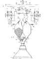
- the only figure of the drawing shows a schematic cross section through the upper part of a large blast furnace, which is equipped with the pressure compensation device according to the invention.
- a blast furnace 1 operated in a high-pressure process is shown as a shaft furnace.
- the top gas exhaust pipes, since they are not directly related to the invention, are not included in the drawing.
- Above the furnace head 1 a is the top seal 2.
- This essentially consists of the lock bunkers 3 and 4 with the sealing elements described below.
- the lock bunkers 3 and 4 can be closed by means of conventional sealing flaps 7 and 8, the sealing seats of which lie outside the path of the material to be loaded.
- cleaned top gas is fed through the pipe 13 into the lock bunker 4 and through the branch pipe 13a into the lock bunker 3 for pressure equalization.
- Shut-off fittings 14 and 15 are located in the pipeline sections that are suitable for switching the clean gas supply on or off.
- the pressure compensation pipeline 18 is connected, which connects the two lock bunkers 3 and 4 with each other in accordance with the basic idea of the invention.
- Each of the lock bunkers 3 and 4 can be separated from the entire pipeline system by means of the shut-off fittings 19 and 20.
- the blast gas flow moving in the pipeline 13, in the branch pipeline 13a or in the pressure compensation pipeline 18 is conducted in the opposite direction of flow through the bypass pipeline 18a.
- shut-off valve pairs 21a and 21b serve for the opposite switching of the gas flow.
- the blast furnace gas to be discharged is conducted from branches 16 and 17 via expansion pipelines 22 and 23, in which shut-off valves 24 and 25 are also switched on, to silencer 26 and from there into the open air 27.
- the invention works in the following cycle:
- the lock bunker 3 is partially filled with the loading goods (fuel, such as coke, melt materials, such as pig iron oiler).
- fuel such as coke
- melt materials such as pig iron oiler
- the interior of the lock bunker 3 is still under atmospheric pressure.
- the contents of the lock bunker 4 were previously emptied into the furnace 1 with the sealing flap 8 closed and the sealing flap 12 open or the loading material holding flap 10 open.
- the gas pressure of the furnace 1 prevails in the lock bunker 4 in this phase.
- the clean gas is entered after the shut-off valve 21b has been closed and after the shut-off valve 14 has been opened through the two-way pipeline 13a until the otherwise measured internal furnace chamber pressure is reached.
- the cycle described in this way is initiated again by opening the sealing flap 11 and the loading material holding flap 9 and by discharging the loading material from the lock bunker 3 into the furnace 1 with the analogous steps for the lock bunker 4.
Landscapes
- Engineering & Computer Science (AREA)
- Chemical & Material Sciences (AREA)
- Manufacturing & Machinery (AREA)
- Materials Engineering (AREA)
- Metallurgy (AREA)
- Organic Chemistry (AREA)
- Blast Furnaces (AREA)
Priority Applications (1)
| Application Number | Priority Date | Filing Date | Title |
|---|---|---|---|
| EP81103379A EP0064090A1 (fr) | 1981-05-05 | 1981-05-05 | Installation pour l'équilibrage des pressions pour fours à cuve fonctionnant en surpression, en particulier pour hauts fourneaux |
Applications Claiming Priority (1)
| Application Number | Priority Date | Filing Date | Title |
|---|---|---|---|
| EP81103379A EP0064090A1 (fr) | 1981-05-05 | 1981-05-05 | Installation pour l'équilibrage des pressions pour fours à cuve fonctionnant en surpression, en particulier pour hauts fourneaux |
Publications (1)
| Publication Number | Publication Date |
|---|---|
| EP0064090A1 true EP0064090A1 (fr) | 1982-11-10 |
Family
ID=8187697
Family Applications (1)
| Application Number | Title | Priority Date | Filing Date |
|---|---|---|---|
| EP81103379A Withdrawn EP0064090A1 (fr) | 1981-05-05 | 1981-05-05 | Installation pour l'équilibrage des pressions pour fours à cuve fonctionnant en surpression, en particulier pour hauts fourneaux |
Country Status (1)
| Country | Link |
|---|---|
| EP (1) | EP0064090A1 (fr) |
Citations (6)
| Publication number | Priority date | Publication date | Assignee | Title |
|---|---|---|---|---|
| DE2016205A1 (de) * | 1970-04-04 | 1971-10-07 | Demag Ag, 4100 Duisburg | Verfahren und Einrichtung zum Aus gleichen der Gasdrucke von Schleusen kammern und Ofenraum von Schachtofen, insbesondere von Hochofen |
| JPS5480204A (en) * | 1977-12-12 | 1979-06-26 | Sumitomo Heavy Ind Ltd | Self-cooling apparatus |
| JPS54131509A (en) * | 1978-04-05 | 1979-10-12 | Ishikawajima Harima Heavy Ind Co Ltd | Equalizing evacuation at furnace top |
| JPS54132407A (en) * | 1978-04-05 | 1979-10-15 | Ishikawajima Harima Heavy Ind Co Ltd | Uniformizing method for pressure at furnace top |
| JPS5620107A (en) * | 1979-07-25 | 1981-02-25 | Sumitomo Metal Ind Ltd | Recovering method of gas for uniform pressure exhausting of blast furnace |
| DE2945045A1 (de) * | 1979-11-08 | 1981-05-27 | Mannesmann Demag Ag, 4100 Duisburg | Druckausgleichseinrichtung fuer gegenueber der atomosphaere im ueberdruck bestriebene schachtoefen, insbesondere fuer grosshochoefen |
-
1981
- 1981-05-05 EP EP81103379A patent/EP0064090A1/fr not_active Withdrawn
Patent Citations (6)
| Publication number | Priority date | Publication date | Assignee | Title |
|---|---|---|---|---|
| DE2016205A1 (de) * | 1970-04-04 | 1971-10-07 | Demag Ag, 4100 Duisburg | Verfahren und Einrichtung zum Aus gleichen der Gasdrucke von Schleusen kammern und Ofenraum von Schachtofen, insbesondere von Hochofen |
| JPS5480204A (en) * | 1977-12-12 | 1979-06-26 | Sumitomo Heavy Ind Ltd | Self-cooling apparatus |
| JPS54131509A (en) * | 1978-04-05 | 1979-10-12 | Ishikawajima Harima Heavy Ind Co Ltd | Equalizing evacuation at furnace top |
| JPS54132407A (en) * | 1978-04-05 | 1979-10-15 | Ishikawajima Harima Heavy Ind Co Ltd | Uniformizing method for pressure at furnace top |
| JPS5620107A (en) * | 1979-07-25 | 1981-02-25 | Sumitomo Metal Ind Ltd | Recovering method of gas for uniform pressure exhausting of blast furnace |
| DE2945045A1 (de) * | 1979-11-08 | 1981-05-27 | Mannesmann Demag Ag, 4100 Duisburg | Druckausgleichseinrichtung fuer gegenueber der atomosphaere im ueberdruck bestriebene schachtoefen, insbesondere fuer grosshochoefen |
Non-Patent Citations (4)
| Title |
|---|
| PATENT ABSTRACTS OF JAPAN, Band 3, Nr. 152, 14. Dezember 1979; & JP-A-54 131 509 (Ishikawajima Harima Jukogyo) (12.10.1979) Seite 159C67 * |
| PATENT ABSTRACTS OF JAPAN, Band 3, Nr. 157, 22. Dezember 1979; & JP-A-54 132 407 (Ishikawajima Harima Jukogyo) (15.10.1979) Seite 27C68 * |
| PATENT ABSTRACTS OF JAPAN, Band 3., Nr. 100, 24. August 1979; & JP-A-54 080 204 (Sumitomo Jukikai Kogyo) (26.06.1979) Seite 125C56 * |
| PATENT ABSTRACTS OF JAPAN, Band 5, Nr. 71, 13. Mai 1981; & JP-A-56 020 107 (Sumitomo Kinzoku Kogyo) (25.02.1981) Seite C54 * |
Similar Documents
| Publication | Publication Date | Title |
|---|---|---|
| DE69317107T2 (de) | Verfahren zum Evakuieren von festen Abfällen aus einer Gasreinigungsvorrichtung | |
| DE69330182T2 (de) | Heissgasfilter | |
| DE19709329C2 (de) | Glockenloser Gichtverschluß für Schachtöfen, insbesondere Hochöfen | |
| CA1084264A (fr) | Soupapes d'equilibrage de pression | |
| DE3418311A1 (de) | Entnahmevorrichtung fuer feststoffproben | |
| DE102006000785A1 (de) | Filterservicesystem und -verfahren | |
| CA1135958A (fr) | Methode et dispositif de recuperation des gaz de voute de hauts-fourneaux et autres | |
| DE2945045C2 (de) | Druckausgleichseinrichtung für gegenüber der Atomosphäre im Überdruck bestriebene Schachtöfen, insbesondere für Großhochöfen | |
| DE2443552C3 (de) | Vorrichtung zum Einbringen von strömendem Gut in einen Verbraucher | |
| EP0064090A1 (fr) | Installation pour l'équilibrage des pressions pour fours à cuve fonctionnant en surpression, en particulier pour hauts fourneaux | |
| DE3330635A1 (de) | Vortriebsschild | |
| DE3632724A1 (de) | Doppelschleusen-gichtverschluss fuer schachtoefen, insbesondere hochoefen | |
| EP0253273A1 (fr) | Appareil pour dépoussiérer des gaz | |
| US3041059A (en) | Combined gas cleaner and cooler | |
| DE3841756A1 (de) | Kraftanlage zur verbrennung von brennstoff in einem wirbelbett | |
| DE2735180C2 (de) | Schüttgutbehälter für partikelförmiges Feststoffmaterial | |
| US4377278A (en) | Apparatus for equalizing pressure in shaft furnaces | |
| US3297432A (en) | Blast furnace charging apparatus pressurization | |
| DE3044902A1 (de) | Waermeaustauscher | |
| DE2824306A1 (de) | Absperrvorrichtung an gasleitungen grossen querschnitts | |
| DE2016205A1 (de) | Verfahren und Einrichtung zum Aus gleichen der Gasdrucke von Schleusen kammern und Ofenraum von Schachtofen, insbesondere von Hochofen | |
| DE3245374C1 (de) | Verfahren und Einrichtung zum Druckreduzieren von Gichtgasen einer oberen Druckstufe | |
| DE2515583C3 (de) | Füllbehälter für vorgetrocknete Feinkohle auf Füllwagen für Verkokungsbatterien | |
| SU1082327A3 (ru) | Устройство дл выравнивани давлени в бункерах загрузочного устройства доменной печи | |
| DE868128C (de) | Einschleusvorrichtung fuer pneumatische Foerderanlagen |
Legal Events
| Date | Code | Title | Description |
|---|---|---|---|
| PUAI | Public reference made under article 153(3) epc to a published international application that has entered the european phase |
Free format text: ORIGINAL CODE: 0009012 |
|
| 17P | Request for examination filed |
Effective date: 19810917 |
|
| AK | Designated contracting states |
Designated state(s): AT BE FR GB IT LU NL SE |
|
| ITCL | It: translation for ep claims filed |
Representative=s name: MODIANO & ASSOCIATI S.R.L. |
|
| EL | Fr: translation of claims filed | ||
| TCNL | Nl: translation of patent claims filed | ||
| STAA | Information on the status of an ep patent application or granted ep patent |
Free format text: STATUS: THE APPLICATION IS DEEMED TO BE WITHDRAWN |
|
| 18D | Application deemed to be withdrawn |
Effective date: 19840508 |
|
| RIN1 | Information on inventor provided before grant (corrected) |
Inventor name: BAERMANN, HANS |