EP0064093A1 - Dispositif de commutation électrique pour la représentation d'une installation de barres omnibus avec un enregistreur de perturbation - Google Patents
Dispositif de commutation électrique pour la représentation d'une installation de barres omnibus avec un enregistreur de perturbation Download PDFInfo
- Publication number
- EP0064093A1 EP0064093A1 EP81108644A EP81108644A EP0064093A1 EP 0064093 A1 EP0064093 A1 EP 0064093A1 EP 81108644 A EP81108644 A EP 81108644A EP 81108644 A EP81108644 A EP 81108644A EP 0064093 A1 EP0064093 A1 EP 0064093A1
- Authority
- EP
- European Patent Office
- Prior art keywords
- assigned
- bus
- switching
- contacts
- relays
- Prior art date
- Legal status (The legal status is an assumption and is not a legal conclusion. Google has not performed a legal analysis and makes no representation as to the accuracy of the status listed.)
- Granted
Links
Images

Classifications
-
- H—ELECTRICITY
- H02—GENERATION; CONVERSION OR DISTRIBUTION OF ELECTRIC POWER
- H02B—BOARDS, SUBSTATIONS OR SWITCHING ARRANGEMENTS FOR THE SUPPLY OR DISTRIBUTION OF ELECTRIC POWER
- H02B1/00—Frameworks, boards, panels, desks, casings; Details of substations or switching arrangements
- H02B1/24—Circuit arrangements for boards or switchyards
-
- H—ELECTRICITY
- H02—GENERATION; CONVERSION OR DISTRIBUTION OF ELECTRIC POWER
- H02J—ELECTRIC POWER NETWORKS; CIRCUIT ARRANGEMENTS OR SYSTEMS FOR SUPPLYING OR DISTRIBUTING ELECTRIC POWER; SYSTEMS FOR STORING ELECTRIC ENERGY
- H02J13/00—Circuit arrangements for providing remote monitoring or remote control of equipment in a power distribution network
- H02J13/13—Circuit arrangements for providing remote monitoring or remote control of equipment in a power distribution network characterised by the transmission of data to equipment in the power network
- H02J13/1321—Circuit arrangements for providing remote monitoring or remote control of equipment in a power distribution network characterised by the transmission of data to equipment in the power network using a wired telecommunication network or a data transmission bus
-
- H—ELECTRICITY
- H02—GENERATION; CONVERSION OR DISTRIBUTION OF ELECTRIC POWER
- H02J—ELECTRIC POWER NETWORKS; CIRCUIT ARRANGEMENTS OR SYSTEMS FOR SUPPLYING OR DISTRIBUTING ELECTRIC POWER; SYSTEMS FOR STORING ELECTRIC ENERGY
- H02J13/00—Circuit arrangements for providing remote monitoring or remote control of equipment in a power distribution network
- H02J13/18—Circuit arrangements for providing remote monitoring or remote control of equipment in a power distribution network characterised by the remotely-controlled equipment, e.g. converters or transformers
- H02J13/333—Circuit arrangements for providing remote monitoring or remote control of equipment in a power distribution network characterised by the remotely-controlled equipment, e.g. converters or transformers the equipment forming part of substations
-
- H—ELECTRICITY
- H02—GENERATION; CONVERSION OR DISTRIBUTION OF ELECTRIC POWER
- H02J—ELECTRIC POWER NETWORKS; CIRCUIT ARRANGEMENTS OR SYSTEMS FOR SUPPLYING OR DISTRIBUTING ELECTRIC POWER; SYSTEMS FOR STORING ELECTRIC ENERGY
- H02J13/00—Circuit arrangements for providing remote monitoring or remote control of equipment in a power distribution network
- H02J13/18—Circuit arrangements for providing remote monitoring or remote control of equipment in a power distribution network characterised by the remotely-controlled equipment, e.g. converters or transformers
- H02J13/34—Circuit arrangements for providing remote monitoring or remote control of equipment in a power distribution network characterised by the remotely-controlled equipment, e.g. converters or transformers the equipment being switches, relays or circuit breakers
-
- Y—GENERAL TAGGING OF NEW TECHNOLOGICAL DEVELOPMENTS; GENERAL TAGGING OF CROSS-SECTIONAL TECHNOLOGIES SPANNING OVER SEVERAL SECTIONS OF THE IPC; TECHNICAL SUBJECTS COVERED BY FORMER USPC CROSS-REFERENCE ART COLLECTIONS [XRACs] AND DIGESTS
- Y02—TECHNOLOGIES OR APPLICATIONS FOR MITIGATION OR ADAPTATION AGAINST CLIMATE CHANGE
- Y02E—REDUCTION OF GREENHOUSE GAS [GHG] EMISSIONS, RELATED TO ENERGY GENERATION, TRANSMISSION OR DISTRIBUTION
- Y02E60/00—Enabling technologies; Technologies with a potential or indirect contribution to GHG emissions mitigation
-
- Y—GENERAL TAGGING OF NEW TECHNOLOGICAL DEVELOPMENTS; GENERAL TAGGING OF CROSS-SECTIONAL TECHNOLOGIES SPANNING OVER SEVERAL SECTIONS OF THE IPC; TECHNICAL SUBJECTS COVERED BY FORMER USPC CROSS-REFERENCE ART COLLECTIONS [XRACs] AND DIGESTS
- Y04—INFORMATION OR COMMUNICATION TECHNOLOGIES HAVING AN IMPACT ON OTHER TECHNOLOGY AREAS
- Y04S—SYSTEMS INTEGRATING TECHNOLOGIES RELATED TO POWER NETWORK OPERATION, COMMUNICATION OR INFORMATION TECHNOLOGIES FOR IMPROVING THE ELECTRICAL POWER GENERATION, TRANSMISSION, DISTRIBUTION, MANAGEMENT OR USAGE, i.e. SMART GRIDS
- Y04S40/00—Systems for electrical power generation, transmission, distribution or end-user application management characterised by the use of communication or information technologies, or communication or information technology specific aspects supporting them
- Y04S40/12—Systems for electrical power generation, transmission, distribution or end-user application management characterised by the use of communication or information technologies, or communication or information technology specific aspects supporting them characterised by data transport means between the monitoring, controlling or managing units and monitored, controlled or operated electrical equipment
- Y04S40/124—Systems for electrical power generation, transmission, distribution or end-user application management characterised by the use of communication or information technologies, or communication or information technology specific aspects supporting them characterised by data transport means between the monitoring, controlling or managing units and monitored, controlled or operated electrical equipment using wired telecommunication networks or data transmission busses
Definitions
- the invention relates to an electrical circuit arrangement for emulating a busbar system with a fault recorder of the type specified in the preamble of claim 1, as is known, for example, from German Patent 1,264,580.
- Such circuit arrangements are used for voltage measurement for the purpose of testing and monitoring each of the interconnected parts of busbar systems. To do this, use the voltage transformers in the branches of the busbar systems. For monitoring purposes, such circuit arrangements also have so-called fault recorders which, in the event of a voltage interruption or a voltage dip, turn on within approximately 20 milliseconds in order to write a fault log.
- the invention has for its object to design a circuit arrangement of the type mentioned so that the fault recorder at normal, ie. H. intentional switching operations do not respond even if they exceed the response time of the fault recorder.
- SS 1, SS 2 and SS 3 each denote a three-phase busbar with neutral.
- Three branches Al, A2, A3 are available for these busbar lines, which can be connected to one of the busbar lines using isolating switches Q1, Q2, Q3 and circuit breakers QO.
- Each of the three branches has a voltage converter T1, T2 or T3. These elements form the primary system.
- the voltage transformers are connected to the circuit arrangement for emulating the primary system via corresponding supply lines.
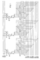
- the individual connecting lines which correspond to those of the branches to each of the busbar lines, are connected to contact sets K1, K2 and K3 of switching relay groups BC 171, BC 147, CC 171, which are open in the idle state, which, with the appropriate connection of a branch, a connection to the busbar simulation lines 1SU, 1SV, 1SW, 1SN; Manufacture 2SU, 2SV, 2SW, 2SN and 3SU, 3SV, 3SW, 3SN.
- the control relays K1, K2 and K3 are grouped together in accordance with their assignment to the respective busbar line, the group of busbar line SS 1 designated BC3, the group of busbar line SS 2 designated BC 33 and the group of busbar line SS designated CC3 3 is assigned.
- Each of these relays in each group is provided with two changeover contacts.
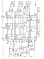
- the break contacts of the first changeover contacts each form a series connection AK1-AK11, which together with the excitation coils of fault recorder operating relays AC21, Kl; BC21, Kl and CC21, K1 are connected in series and form their excitation circuits.
- the break contacts of the second changeover contacts of the control relays K1, K2, K3 form second series circuits AK2-AK12 which are parallel to the first series circuit. Both series connections are connected to one another on their sides facing the fault recorder operating relays.
- the other ends AK1 of the first series circuits AK1-AK11 are with the positive pole of an excitation current source
- the other ends AK2 of the second series circuits AK2-AK12 are each with a control means in the form of a transistor Vl, V2, V3 of the control devices for the fault recorder interruption AC21, BC21, CC21 connected to which switching means AC21, K2; BC 21, K2 and CC21, K2 are assigned to interrupt the recorder.
- the two NO contacts of each of the changeover switches assigned to the control relays K1, K2, K3 are connected to one another and to a field coil K1, K2, K3 of switching relays, which are also grouped according to the control relays in groups BC171, BC147 and CC171.
- the BC171 group of busbars SS 1 is the Group BC147 of the busbar line SS 2 and group CC171 of the busbar line SS 3, each with a relay coil Kl, K2, K3 assigned to each branch.
- the circuit arrangement according to FIGS. 1 and 2 has the following effect that even when a number of branches are connected to a single busbar line, only one voltage converter T1, T2 and T3 of one of these branches A1, A2, A3 is used for the voltage measurement: It it is assumed that the isolating switches Q1 of the branches Al and A2 and the associated circuit breakers QO are closed and thus the branches Al and A2 are connected to the busbar line SS 1. By closing the auxiliary contacts of the same designation assigned to the isolating switch Q1 and the circuit breaker QO in FIG. 2, the relay coils BC3, K1 and K2 are excited.
- the two changeover switches assigned to these relays are actuated, with the result that the cut-in relay BC171, Kl is energized, its contacts BC171, Kl (FIG. 1), closes and connects the voltage converter T1 to the circuit arrangement.
- the activation relay BC171, K2, which is also controlled by the changeover contact of BC3, K2, cannot be energized because by actuating the changeover contact of the control relay BC3, Kl, the excitation circuits of all excitation circuits of the activation relay in the contact chain AK1-AK11 to the right of it are interrupted.
- the switchover time for the above-described process of disconnecting a voltage converter from the circuit arrangement and connecting it to another voltage converter is longer than the response time of the fault recorders assigned to the individual busbar lines in order to prepare a fault report in the event of a voltage dip.
- the present circuit arrangement has the fault recorder control devices AC21, BC21 and CC21.
- Each of these fault recorder control devices contains a fault recorder operating relay Kl and a fault recorder interruption relay K2.
- a break contact is assigned to each.
- the normally closed contacts of each fault recorder control device are connected in series and form the circuit of the respectively assigned fault recorder R1, R2 or R3.
- the voltage converter T2 is thus connected to the replica of the busbar line SS 1 of the circuit arrangement.
- the Excitation circuit of the fault recorder operating relay AC21, Kl interrupted and the fault recorder interrupt relay AC21, K2 energized after switching on the transistor V1.
- the normally closed contact AC21, Kl closes and the normally closed contact AC21, K2 opens.
- the excitation circuit of the fault recorder Rl is thus still open.
- the excitation of the fault recorder interrupter relay AC21, K2 is interrupted, so that its normally closed contact closes the circuit for the fault recorder R1 and into it Readiness to write transferred.
- Fig. 3 it is shown in principle with which means and in what way such an interruption of the relevant fault recorder R1, R2 or R3 is achieved.
- relays AC21, Kl; BC21, Kl and CC21, K1 (Fig. 2) are polarized relays. These are normally in the starting position, so that the rest contacts assigned to them are closed.
- at least one of the control relays of the relevant group BC3, BC33 or CC3 changes its switching state and briefly interrupts the plus potential at the base resistor R12 of the voltage divider Rll, R12 of the transistor in question in the setting circuit of it assigned polarized relay K2.
- the transistor then controls and implements the polarized relay K2 assigned to it.
- the fault recorder concerned should also be registered in a be interrupted in such cases.
Landscapes
- Engineering & Computer Science (AREA)
- Power Engineering (AREA)
- Testing Electric Properties And Detecting Electric Faults (AREA)
- Testing Of Short-Circuits, Discontinuities, Leakage, Or Incorrect Line Connections (AREA)
Priority Applications (1)
| Application Number | Priority Date | Filing Date | Title |
|---|---|---|---|
| AT81108644T ATE11845T1 (de) | 1981-04-24 | 1981-10-21 | Elektrische schaltungsanordnung zur nachbildung einer sammelschienenanlage mit einem stoerschreiber. |
Applications Claiming Priority (2)
| Application Number | Priority Date | Filing Date | Title |
|---|---|---|---|
| DE3116393A DE3116393C1 (de) | 1981-04-24 | 1981-04-24 | Elektrische Schaltungsanordnung zur Nachbildung einer Sammelschienenanlage mit einem Störschreiber |
| DE3116393 | 1981-04-24 |
Publications (2)
| Publication Number | Publication Date |
|---|---|
| EP0064093A1 true EP0064093A1 (fr) | 1982-11-10 |
| EP0064093B1 EP0064093B1 (fr) | 1985-02-13 |
Family
ID=6130786
Family Applications (1)
| Application Number | Title | Priority Date | Filing Date |
|---|---|---|---|
| EP81108644A Expired EP0064093B1 (fr) | 1981-04-24 | 1981-10-21 | Dispositif de commutation électrique pour la représentation d'une installation de barres omnibus avec un enregistreur de perturbation |
Country Status (3)
| Country | Link |
|---|---|
| EP (1) | EP0064093B1 (fr) |
| AT (1) | ATE11845T1 (fr) |
| DE (1) | DE3116393C1 (fr) |
Cited By (1)
| Publication number | Priority date | Publication date | Assignee | Title |
|---|---|---|---|---|
| CN109672265A (zh) * | 2019-03-01 | 2019-04-23 | 深圳供电局有限公司 | 电控母联开关驱动装置及其控制方法 |
Citations (2)
| Publication number | Priority date | Publication date | Assignee | Title |
|---|---|---|---|---|
| DE1264580B (de) * | 1965-09-15 | 1968-03-28 | Siemens Ag | Schaltung fuer die Nachbildung der Sammelschienenspannung |
| DE2753659A1 (de) * | 1977-12-02 | 1979-06-07 | Ruhrtal Gmbh | Sammelschienen-spannungsnachbildung |
-
1981
- 1981-04-24 DE DE3116393A patent/DE3116393C1/de not_active Expired
- 1981-10-21 EP EP81108644A patent/EP0064093B1/fr not_active Expired
- 1981-10-21 AT AT81108644T patent/ATE11845T1/de not_active IP Right Cessation
Patent Citations (2)
| Publication number | Priority date | Publication date | Assignee | Title |
|---|---|---|---|---|
| DE1264580B (de) * | 1965-09-15 | 1968-03-28 | Siemens Ag | Schaltung fuer die Nachbildung der Sammelschienenspannung |
| DE2753659A1 (de) * | 1977-12-02 | 1979-06-07 | Ruhrtal Gmbh | Sammelschienen-spannungsnachbildung |
Cited By (1)
| Publication number | Priority date | Publication date | Assignee | Title |
|---|---|---|---|---|
| CN109672265A (zh) * | 2019-03-01 | 2019-04-23 | 深圳供电局有限公司 | 电控母联开关驱动装置及其控制方法 |
Also Published As
| Publication number | Publication date |
|---|---|
| ATE11845T1 (de) | 1985-02-15 |
| EP0064093B1 (fr) | 1985-02-13 |
| DE3116393C1 (de) | 1982-11-04 |
Similar Documents
| Publication | Publication Date | Title |
|---|---|---|
| EP0224711B1 (fr) | Procédure d'actionnement protégé contre des erreurs de commutation des commutateurs d'une installation de commutation | |
| DE3727939A1 (de) | Schaltungsanordnung fuer textilmaschinen, insbesondere spinnmaschinen mit einzelmotorantrieb der spindeln | |
| EP0266567B1 (fr) | Procédé de surveillance et de commande d'un sélecteur d'antenne et sélecteur d'antenne pour la mise en oeuvre du procédé | |
| DE69702869T2 (de) | Sicherheitsrelais | |
| DE4328932C2 (de) | Verfahren und Einrichtung für die Fernabfrage von Meßstellen | |
| DE2356959A1 (de) | Phasenvergleichs-relaisanordnung | |
| EP0064093B1 (fr) | Dispositif de commutation électrique pour la représentation d'une installation de barres omnibus avec un enregistreur de perturbation | |
| DE3738493C2 (de) | Fehlerortungseinrichtung | |
| DE3830742C2 (fr) | ||
| EP0064094B1 (fr) | Dispositif de commutation électrique pour la représentation d'une installation de barres omnibus | |
| DE968644C (de) | Schaltung fuer reversierbare, mit Drehstrom betriebene elektromotorische Antriebe in Eisenbahnsicherungsanlagen | |
| DE4009483C1 (en) | Self monitoring short circuit detector - has motor supply leads with DC transducers coupled via amplifier to self testing control | |
| DE592378C (de) | Selektivschutzsystem fuer Verteilungsnetze | |
| DE3419752A1 (de) | Verfahren zur ueberwachung des ausloese- bzw. einschaltkreises eines leistungsschalters | |
| DE2602910C2 (de) | Elektrische Sicherheitsschaltung von Maschinen | |
| DE664878C (de) | Schaltanordnung zum Umschalten elektrischer Schaltanlagen von selbsttaetigem auf Handbetrieb | |
| DE2440400C3 (de) | Anordnung zur Ein- und Ausschaltung von Stromkreisen | |
| DE1640952C3 (de) | Verfahren zum Steuern einer be liebigen Zahl elektrisch steuerbarer elek tnscher Schalter nach einem Programm | |
| DE1540072C (de) | Verfahren zum Steuern einer beliebigen Zahl elektrisch steuerbarer elektrischer Schalter nach einem Programm | |
| DE903719C (de) | Schaltungsanordnung fuer die Zuschaltung der fuer den Betrieb einer Schutzeinrichtung erforderlichen Hilfsspannung bei aus drei oder vier Leitern (drei Phasen und Erde) bestehenden zu schuetzenden Drehstromnetzen bzw. Drehstromeinrichtungen | |
| DE762559C (de) | Einrichtung zur elektrischen Fernsteuerung, insbesondere mehrerer Schalter oder Ventile | |
| DE601682C (de) | Schaltungsanordnung bei Fernsteuerungsanlagen | |
| AT232607B (de) | Elektronische Relaisschaltungsanordnung | |
| DE385304C (de) | Schaltungsanordnung zur selektiven Abschaltung paralleler Kabel, die eine Unterstation mit einer Zentrale verbinden | |
| DE1465953C (de) | Verfahren zum Abschalten einzelner Anlageteile aus einem Steuer und/oder Verriegelungssystem einer aus mehreren Teilen bestehenden Gesamtanlage |
Legal Events
| Date | Code | Title | Description |
|---|---|---|---|
| PUAI | Public reference made under article 153(3) epc to a published international application that has entered the european phase |
Free format text: ORIGINAL CODE: 0009012 |
|
| 17P | Request for examination filed |
Effective date: 19811021 |
|
| AK | Designated contracting states |
Designated state(s): AT BE CH FR IT NL SE |
|
| ITF | It: translation for a ep patent filed | ||
| GRAA | (expected) grant |
Free format text: ORIGINAL CODE: 0009210 |
|
| AK | Designated contracting states |
Designated state(s): AT BE CH FR IT LI NL SE |
|
| REF | Corresponds to: |
Ref document number: 11845 Country of ref document: AT Date of ref document: 19850215 Kind code of ref document: T |
|
| ET | Fr: translation filed | ||
| PLBE | No opposition filed within time limit |
Free format text: ORIGINAL CODE: 0009261 |
|
| STAA | Information on the status of an ep patent application or granted ep patent |
Free format text: STATUS: NO OPPOSITION FILED WITHIN TIME LIMIT |
|
| 26N | No opposition filed | ||
| PGFP | Annual fee paid to national office [announced via postgrant information from national office to epo] |
Ref country code: AT Payment date: 19861003 Year of fee payment: 6 |
|
| PGFP | Annual fee paid to national office [announced via postgrant information from national office to epo] |
Ref country code: NL Payment date: 19861031 Year of fee payment: 6 |
|
| PG25 | Lapsed in a contracting state [announced via postgrant information from national office to epo] |
Ref country code: AT Effective date: 19871021 |
|
| PG25 | Lapsed in a contracting state [announced via postgrant information from national office to epo] |
Ref country code: SE Effective date: 19871022 |
|
| PG25 | Lapsed in a contracting state [announced via postgrant information from national office to epo] |
Ref country code: LI Effective date: 19871031 Ref country code: CH Effective date: 19871031 Ref country code: BE Effective date: 19871031 |
|
| BERE | Be: lapsed |
Owner name: SIEMENS A.G. BERLIN UND MUNCHEN Effective date: 19871031 |
|
| PG25 | Lapsed in a contracting state [announced via postgrant information from national office to epo] |
Ref country code: NL Effective date: 19880501 |
|
| NLV4 | Nl: lapsed or anulled due to non-payment of the annual fee | ||
| PG25 | Lapsed in a contracting state [announced via postgrant information from national office to epo] |
Ref country code: FR Free format text: LAPSE BECAUSE OF NON-PAYMENT OF DUE FEES Effective date: 19880630 |
|
| REG | Reference to a national code |
Ref country code: CH Ref legal event code: PL |
|
| REG | Reference to a national code |
Ref country code: FR Ref legal event code: ST |
|
| EUG | Se: european patent has lapsed |
Ref document number: 81108644.6 Effective date: 19880707 |