EP0064098A2 - Force-transmission device - Google Patents
Force-transmission device Download PDFInfo
- Publication number
- EP0064098A2 EP0064098A2 EP81109664A EP81109664A EP0064098A2 EP 0064098 A2 EP0064098 A2 EP 0064098A2 EP 81109664 A EP81109664 A EP 81109664A EP 81109664 A EP81109664 A EP 81109664A EP 0064098 A2 EP0064098 A2 EP 0064098A2
- Authority
- EP
- European Patent Office
- Prior art keywords
- transmission device
- toggle
- power transmission
- piece
- frame piece
- Prior art date
- Legal status (The legal status is an assumption and is not a legal conclusion. Google has not performed a legal analysis and makes no representation as to the accuracy of the status listed.)
- Granted
Links
Images


Classifications
-
- A—HUMAN NECESSITIES
- A61—MEDICAL OR VETERINARY SCIENCE; HYGIENE
- A61H—PHYSICAL THERAPY APPARATUS, e.g. DEVICES FOR LOCATING OR STIMULATING REFLEX POINTS IN THE BODY; ARTIFICIAL RESPIRATION; MASSAGE; BATHING DEVICES FOR SPECIAL THERAPEUTIC OR HYGIENIC PURPOSES OR SPECIFIC PARTS OF THE BODY
- A61H1/00—Apparatus for passive exercising; Vibrating apparatus; Chiropractic devices, e.g. body impacting devices, external devices for briefly extending or aligning unbroken bones
- A61H1/02—Stretching or bending or torsioning apparatus for exercising
- A61H1/0218—Drawing-out devices
-
- A—HUMAN NECESSITIES
- A61—MEDICAL OR VETERINARY SCIENCE; HYGIENE
- A61H—PHYSICAL THERAPY APPARATUS, e.g. DEVICES FOR LOCATING OR STIMULATING REFLEX POINTS IN THE BODY; ARTIFICIAL RESPIRATION; MASSAGE; BATHING DEVICES FOR SPECIAL THERAPEUTIC OR HYGIENIC PURPOSES OR SPECIFIC PARTS OF THE BODY
- A61H2201/00—Characteristics of apparatus not provided for in the preceding codes
- A61H2201/16—Physical interface with patient
- A61H2201/1602—Physical interface with patient kind of interface, e.g. head rest, knee support or lumbar support
- A61H2201/164—Feet or leg, e.g. pedal
- A61H2201/1642—Holding means therefor
Definitions
- the invention relates to a power transmission device, in particular for the extension of the human body.
- Such power transmission devices are used in particular in the treatment of the intervertebral discs, hip wear and meniscoparticles and similar diseases of the bone structure in such a way that a stretching of the human body leads to a healing or a relief from the suffering.
- the invention is therefore based on the object of providing a force transmission device which makes it possible in a simple manner to stretch the human body for healing purposes.
- the power transmission device comprises a frame piece integrally composed of an upper spar, a lower spar and two side spars with at least one toggle lock on which a special shoe is arranged by means of a movable eyelet and that it can be moved in all spatial directions.
- This power transmission device consists essentially of a drawbar-like suspension, on the underside of which two special shoes hang. This suspension with the special shoes are attached so that they can be moved in all directions of the room.
- the patient lies on a couch or a bed, the special shoes of this device are put on the patient and hung on the lower beam of the power transmission device.
- the power transmission device is pulled up so that the feet, the legs and the back point upwards and the spaces between the bones or the joints are enlarged by the weight of the human body.
- the middle of the upper spar of the frame piece has a thickening in which a movable loop is fastened, which in turn is arranged hanging on a hook located at the lower end of a pulley block.
- the power transmission device is generally pulled up by a pulley system, one end of which is attached to the ceiling and the other end of which is attached to a loop.
- This loop is attached in a thickening in the middle of the upper spar of the frame piece. The loop is chosen so large that the frame piece on the lower hook of the pulley remains freely movable.
- At least one toggle lock is slidably arranged on the lower spar of the frame piece serving as a rail.
- the lower spar of the frame piece serves as a rail.
- two toggle locks are arranged over this rail, which are laterally displaceable.
- These toggle fasteners serve as brackets and suspension devices for the special shoes.
- the possibility of sliding the toggle locks on the lower spar allows a patient's legs to be spread more or less.
- the toggle closure has a claw piece, an eyelet holder, a threaded piece and a threaded rod with a toggle holder, in which the toggle which is rotatable about a bolt is fastened.
- the toggle clasp grips like a claw around the lower spar of the frame piece. At the lower end of the claw fasteners are attached, in which eyelets or rings are attached.
- the special shoes are hooked onto these eyelets using, for example, snap hooks.
- the special shoes have an upper shoe with a sole, a base plate and a fastening plate, the sole, the base plate and the fastening plate being connected by screws and a ring protruding from the fastening plate, which in by means of a threaded rod connected to it the base plate is screwed.
- the special shoes are attached to the toggle locks in such a way that the sole points to the power transmission device.
- the shoes are suspended by a ring with a threaded rod that is screwed into the mounting plate, the base plate and the sole.
- the upper shoe preferably has tab-shaped buckles adapted to the human foot.
- the special shoe is constructed in such a way that the firm connection of the shoe with the human foot prevents the blood supply from being restricted. This is done, for example, by tab-shaped buckles, which ensure a flat and firm connection between the foot and the shoe without causing blood congestion.
- the advantages achieved by the invention are, in particular, that the force transmission device creates a simple possibility for the orthopedist for the therapy of, for example, intervertebral disc complaints, hip joint wear and meniscopathies.
- the power transmission device can be seen in use.
- An essential component is the acorn-shaped frame piece 1.
- This frame piece 1 is attached to a hook 30 in a hanging manner by means of a loop 21.
- two toggle fasteners 2 are ver slidably mounted on a rail 14.
- At the lower end of the toggle fasteners are each an eyelet 12.
- the special shoes 3 are hooked into this eyelet 12 by means of snap hooks 11.
- the patient 27 initially lies on a bed 28.
- the shoes 3 are put on him / her and after the shoes have been hung in the snap hooks 11, they are pulled upwards until the desired position is reached.
- the hoisting is carried out by means of a pulley (not shown in FIG. 1), one end of which is attached to the ceiling 29 and the other end engages in the loop 21.
- the loop 21 and the eyelets 12 are chosen so large that the power transmission device remains freely movable.
- the frame piece 1 is composed of an upper spar 23, a lower spar 24 and two side spars 25 and 26 in one piece. In the middle of the upper spar 23 there is a thickening 22 in which the loop 21 is fastened.
- the lower spar 24 serves as a rail 14 for the toggle locks 2.
- the toggle locks 2 can be moved on the rail 14 in accordance with the parts shown in FIG. 2 and can be fixed by means of the toggles 15.
- At the lower end of the toggle fasteners 2 are one Eyelet 12 attached.
- the snap hooks 11 are hooked into these eyelets.
- the rings 9 of the shoes 3 (not shown in FIG. 2) protruding from the fastening plate 7 are suspended in the snap hooks.
- a special shoe 3 is shown in more detail in FIG.
- the special shoe 3 consists of an upper shoe 5, a sole 4, a base plate 6 and a fastening plate 7.
- the fastening plate 7, the base plate 6 are connected to the sole 4 by means of screws 8.
- a ring 9 provided with a threaded rod 10 protrudes from the fastening plate and is used for hanging in the snap hook 11. The threaded rod 10 of the ring 9 is screwed into the base plate.
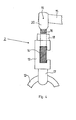
- a toggle closure 2 is shown in section.
- the toggle fastener 2 is composed of a claw piece 13, a threaded piece 18 and an eyelet holder 17.
- the claw fastener 2 is fixed via the toggle 15 which is rotatably mounted in the toggle holder 20 by means of a bolt 19.
- a threaded rod 16 is attached to the toggle holder 20.
- the claw piece 13 engages over the rail 14.
- the threaded rod 16 is rotated into the threaded piece 18 by means of the toggle 15, until the toggle lock 2 is locked on the rail 14.
- the eyelet 12 is fastened, on which in turn a carabiner hook 11 (not shown in FIG. 4) hangs.
Landscapes
- Health & Medical Sciences (AREA)
- Animal Behavior & Ethology (AREA)
- Public Health (AREA)
- Physical Education & Sports Medicine (AREA)
- Rehabilitation Therapy (AREA)
- Life Sciences & Earth Sciences (AREA)
- Epidemiology (AREA)
- General Health & Medical Sciences (AREA)
- Pain & Pain Management (AREA)
- Veterinary Medicine (AREA)
- Orthopedics, Nursing, And Contraception (AREA)
- Transmission Devices (AREA)
- Power Steering Mechanism (AREA)
- Pens And Brushes (AREA)
- Footwear And Its Accessory, Manufacturing Method And Apparatuses (AREA)
Abstract
Description
Die Erfindung betrifft eine Kraftübertragungsvorrichtung, insbesondere zur Extension des menschlichen Körpers.The invention relates to a power transmission device, in particular for the extension of the human body.
Derartige Kraftübertragungsvorrichtungen werden insbesondere bei der Behandlung der Bandscheiben, bei Hüftgelenkverschleiß und Meniskopartien und ähnlichen Krankheiten des Knochenbaues in der Weise angewandt, daß durch Dehnung des menschlichen Körpers eine Heilung bzw. eine Linderung des Leidens eintritt.Such power transmission devices are used in particular in the treatment of the intervertebral discs, hip wear and meniscoparticles and similar diseases of the bone structure in such a way that a stretching of the human body leads to a healing or a relief from the suffering.
Der Erfindung liegt somit die Aufgabe zugrunde, eine Kraftübertragungsvorrichtung zu schaffen, die es auf einfache Weise ermöglicht, den menschlichen Körper zu Heilungszwecken zu dehnen.The invention is therefore based on the object of providing a force transmission device which makes it possible in a simple manner to stretch the human body for healing purposes.
Diese Aufgabe wird erfindungsgemäß dadurch gelöst, daß die Kraftübertragungsvorrichtung ein aus einem Oberholm, einem Unterholm und zwei Seitenholmen einstückig zusammengesetztes Rahmenstück mit mindestens einem Knebelverschluß aufweist, an dem ein Spezialschuh mittels einer beweglichen Öse angeordnet ist und daß sie in allen räumlichen Richtungen bewegbar ist.This object is achieved in that the power transmission device comprises a frame piece integrally composed of an upper spar, a lower spar and two side spars with at least one toggle lock on which a special shoe is arranged by means of a movable eyelet and that it can be moved in all spatial directions.
Diese Kraftübertragungsvorrichtung besteht im wesentlichen aus einer deichselähnlichen Aufhängung, an deren Unterseite zwei Spezialschuhe hängen. Diese Aufhängung mit den Spezialschuhen ist so angebracht, daß sie in allen Richtungen des Raumes bewegbar ist. Der Patient liegt dabei auf einer Liege oder einem Bett, die Spezialschuhe dieser Vorrichtung werden dem Patienten angezogen und an den Unterholm der Kraftübertragungsvorrichtung gehängt. Die Kraftübertragungsvorrichtung wird hochgezogen, so daß die Füße, die Beine und der Rücken nach oben weisen und so durch das Eigengewicht des menschlichen Körpers die Zwischenräume der Knochen bzw. der Gelenke vergrößert werden.This power transmission device consists essentially of a drawbar-like suspension, on the underside of which two special shoes hang. This suspension with the special shoes are attached so that they can be moved in all directions of the room. The patient lies on a couch or a bed, the special shoes of this device are put on the patient and hung on the lower beam of the power transmission device. The power transmission device is pulled up so that the feet, the legs and the back point upwards and the spaces between the bones or the joints are enlarged by the weight of the human body.
Gemäß einer besonders bevorzugten Ausführungsform weist die Mitte des Oberholmes des Rahmenstückes eine Verdickung auf, in der eine bewegliche Schlaufe befestigt ist, die wiederum an einem am unteren Ende eines Flaschenzuges befindlichen Hakens hängend angeordnet ist.According to a particularly preferred embodiment, the middle of the upper spar of the frame piece has a thickening in which a movable loop is fastened, which in turn is arranged hanging on a hook located at the lower end of a pulley block.
Das Hochziehen der Kraftübertragungsvorrichtung geschieht im allgemeinen durch einen Flaschenzug, dessen eines Ende an der Decke und dessen anderes Ende an einer Schlaufe befestigt sind. Diese Schlaufe ist in einer Verdickung in der Mitte des Oberholmes des Rahmenstückes angebracht. Die Schlaufe ist so groß gewählt, daß das Rahmenstück am unteren Haken des Flaschenzuges frei beweglich bleibt.The power transmission device is generally pulled up by a pulley system, one end of which is attached to the ceiling and the other end of which is attached to a loop. This loop is attached in a thickening in the middle of the upper spar of the frame piece. The loop is chosen so large that the frame piece on the lower hook of the pulley remains freely movable.
Vorzugsweise ist mindestens ein Knebelverschluß auf dem als Schiene dienendem Unterholm des Rahmenstückes verschiebbar angeordnet.Preferably, at least one toggle lock is slidably arranged on the lower spar of the frame piece serving as a rail.
Der Unterholm des Rahmenstückes dient als Schiene. Über diese Schiene sind im allgemeinen zwei Knebelverschlüsse angeordnet, die seitlich verschiebbar sind. Diese Knebelverschlüsse dienen als Halterungen und Aufhängevorriehtungen für die Spezialschuhe. Durch die Möglichkeit des Verschiebens der Knebelverschlüsse auf dem Unterholm können die Beine eines Patienten mehr oder weniger gespreizt werden.The lower spar of the frame piece serves as a rail. In general, two toggle locks are arranged over this rail, which are laterally displaceable. These toggle fasteners serve as brackets and suspension devices for the special shoes. The possibility of sliding the toggle locks on the lower spar allows a patient's legs to be spread more or less.
Gemäß einer besonders bevorzugten Ausführungsform weist der Knebelverschluß ein Krallenstück, eine Ösenhalterung, ein Gewindestück und eine Gewindestange mit einer Knebelhalterung auf, in die der um einen Bolzen drehbare Knebel befestigt ist.According to a particularly preferred embodiment, the toggle closure has a claw piece, an eyelet holder, a threaded piece and a threaded rod with a toggle holder, in which the toggle which is rotatable about a bolt is fastened.
Der Knebelverschluß greift krallenartig um den Unterholm des Rahmenstückes. Am unteren Ende der Krallenverschlüsse sind Halterungen angebracht, in die Ösen oder Ringe befestigt sind. An diese Ösen werden die Spezialschuhe durch beispielsweise Karabinerhaken eingehängt.The toggle clasp grips like a claw around the lower spar of the frame piece. At the lower end of the claw fasteners are attached, in which eyelets or rings are attached. The special shoes are hooked onto these eyelets using, for example, snap hooks.
Gemäß einer besonders bevorzugten Ausführungsform weisen die Spezialschuhe einen Oberschuh mit einer Sohle, eine Grundplatte sowie eine Befestigungsplatte auf, wobei die Sohle, die Grundplatte und die Befestigungsplatte mit Schrauben verbunden sind und aus der Befestigungsplatte ein Ring herausragt, der mittels einer mit ihm verbundenen Gewindestange in der Grundplatte verschraubt ist.According to a particularly preferred embodiment, the special shoes have an upper shoe with a sole, a base plate and a fastening plate, the sole, the base plate and the fastening plate being connected by screws and a ring protruding from the fastening plate, which in by means of a threaded rod connected to it the base plate is screwed.
Die Spezialschuhe werden in der Weise an die Knebelverschlüsse angehängt, daß die Sohle zur Kraftübertragungsvorrichtung weist. Die Aufhängung der Schuhe geschieht durch einen Ring mit einer Gewindestange, die in die Befestigungsplatte, der Grundplatte und die Sohle geschraubt wird.The special shoes are attached to the toggle locks in such a way that the sole points to the power transmission device. The shoes are suspended by a ring with a threaded rod that is screwed into the mounting plate, the base plate and the sole.
Vorzugsweise weist der Oberschuh lappenförmige, dem menschlichen Fuß angepaßte Schnallen auf.The upper shoe preferably has tab-shaped buckles adapted to the human foot.
Der Spezialschuh ist so aufgebaut, daß die feste Verbindung des Schuhes mit dem menschlichen Fuß eine Abschnürung der Blutzufuhr verhindern. Dies geschieht durch beispielsweise lappenförmige Schnallen, die eine flächenhafte und feste Verbindung zwischen Fuß und Schuh gewährleisten, ohne einen Blutstau zu verursachen. Die mit der Erfindung erzielten Vorteile bestehen insbesondere darin, daß die Kraftübertragungsvorrichtung eine für den Orthopäden einfache Möglichkeit zur Therapie von beispielsweise Bandscheibenleiden, Hüftgelenkverschleiß und Meniskopathien schafft.The special shoe is constructed in such a way that the firm connection of the shoe with the human foot prevents the blood supply from being restricted. This is done, for example, by tab-shaped buckles, which ensure a flat and firm connection between the foot and the shoe without causing blood congestion. The advantages achieved by the invention are, in particular, that the force transmission device creates a simple possibility for the orthopedist for the therapy of, for example, intervertebral disc complaints, hip joint wear and meniscopathies.
Ein Ausführungsbeispiel der Erfindung ist in der Zeichnung dargestellt und wird im folgenden näher beschrieben. Es zeigen:
- Figur 1 die Kraftübertragungsvorrichtung in der Anwendung
Figur 2 die Aufhängevorrichtung ohne SchuheFigur 3 einen Spezialschuh und- Figur 4 eine Ausführungsform eines Knebelverschlusses im Schnitt dargestellt.
- Figure 1 shows the power transmission device in use
- Figure 2 shows the hanging device without shoes
- Figure 3 shows a special shoe and
- Figure 4 shows an embodiment of a toggle closure in section.
In Figur 1 ist die Kraftübertragungsvorrichtung in Anwendung zu sehen. Wesentlicher Bestandteil ist das aeichselförmige Rahmenstück 1. Dieses Rahmenstück 1 ist mittels einer Schlaufe 21 an einem Haken 30 hängend befestigt. Auf der nach unten weisenden Seite des Rahmenstückes 1 sind zwei Knebelverschlüsse 2 verschiebbar auf einer Schiene 14 angebracht. Am unteren Ende der Knebelverschlüsse befinden sich jeweils eine Öse 12. In diese Öse 12 werden mittels Karabinerhaken 11 die Spezialschuhe 3 eingehängt. Der Patient 27 liegt zunächst auf einem Bett 28. Ihm/werden die Schuhe 3 angezogen und nachdem die Schuhe in die Karabinerhaken 11 eingehängt wurden, nach oben gezogen, bis die gewünschte Stellung erreicht ist. Das Hochziehen erfolgt mittels eines nicht in Figur 1 dargestellten Flaschenzuges dessen eines Ende an der Decke 29 befestigt ist und dessen anderes Ende in die Schlaufe 21 eingreift. Die Schlaufe 21 und die Ösen 12 sind so groß gewählt, daß die Kraftübertragungsvorrichtung frei beweglich bleibt.In Figure 1, the power transmission device can be seen in use. An essential component is the acorn-shaped frame piece 1. This frame piece 1 is attached to a
In Figur 2 ist die Kraftübertragungsvorrichtung ohne Spezialschuhe dargestellt. Das Rahmenstück 1 ist aus einem Oberholm 23 einem Unterholm 24 und zwei Seitenholmen 25 und 26 einstückig zusammengesetzt. In der Mitte des Oberholmes 23 ist eine Verdickung 22 angebracht, in die die Schlaufe 21 befestigt ist. Der Unterholm 24 dient als Schiene 14 für die Knebelverschlüsse 2. Die Knebelverschlüsse 2 sind gemäß der in Figur 2 dargestellten Teile auf der Schiene 14 verschiebbar und mittels der Knebel 15 feststellbar. Am unteren Ende der Knebelverschlüsse 2 sind jeweils eine Öse 12 angebracht. In diese Ösen sind die Karabinerhaken 11 eingehängt. In die Karabinerhaken werden die aus der Befestigungsplatte 7 herausragenden Ringe 9 der in Figur 2 nicht dargestellten Schuhe 3 eingehängt.In Figure 2, the power transmission device is shown without special shoes. The frame piece 1 is composed of an
In Figur 3 ist eine Spezialschuh 3 näher gezeigt. Der Spezialschuh 3 besteht aus einem Oberschuh 5, einer Sohle 4, einer Grundplatte 6 und einer Befestigungsplatte 7. Die Befestigungsplatte 7, die Grundplatte 6 sind mittels Schrauben 8 an der Sohle 4 verbunden. Ein mit einer Gewindestange 10 versehener Ring 9 ragt aus der Befestigungsplatte heraus und dient zur Einhängung in die Karabinerhaken 11. Die Gewindestange 10 des Ringes 9 ist in der Grundplatte eingeschraubt.A
In Figur 4 ist ein Knebelverschluß 2 im Schnitt dargestellt. Der Knebelverschluß 2 setzt sich zusammen aus einem Krallenstück 13, einem Gewindestück 18 sowie einer Ösenhalterung 17. Die Feststellung des Krallenverschlusses 2 erfolgt über den Knebel 15 der mittels eines Bolzens 19 in der Knebelhalterung 20 drehbar gelagert ist. An die Knebelhalterung 20 fügt sich eine Gewindestange 16 an. Das Krallenstück 13 greift über die Schiene 14. Die Gewindestange 16 wird mittels des Knebels 15 so lange in das Gewindestück 18 gedreht, bis der Knebelverschluß 2 auf der Schiene 14 arretiert ist. In die Ösenhalterung 17 ist die Öse 12 befestigt, an der wiederum eine in Figur 4 nicht dargestellter Karabinerhaken 11 hängt.In Figure 4, a
- 1 Rahmenstück1 frame piece
- 2 Knebelverschluß2 toggle fastener
- 3 Spezialschuh3 special shoe
- 4 Sohle4 sole
- 5 Oberschuh5 upper shoe
- 6 Grundplatte6 base plate
- 7 Befestigungsplatte7 mounting plate
- 8 Schrauben8 screws
- 9 Ring9 ring
- 10 Gewindestange10 threaded rod
- 11 Karabinerhaken11 snap hooks
- 12 Öse12 eyelet
- 13 Krallenstück13 claw piece
- 14 Schiene14 rail
- 15 Knebel15 gags
- 16 Gewindestange16 threaded rod
- 17 Ösenhalterung17 eyelet holder
- 18 Gewindestück18 threaded piece
- 19 Bolzen19 bolts
- 20 Knebelhalterung20 toggle bracket
- 21 Schlaufe21 loop
- 22 Verdickung22 thickening
- 23 Oberholm23 Oberholm
- 24 Unterholm24 lower beam
- 25 Seitenholm25 side rails
- 26 Seitenholm26 side spar
- 27 Patient27 patient
- 28 Bett28 bed
- 29 Decke29 blanket
- 30 Haken30 hooks
Claims (6)
dadurch gekennzeichnet,
daß sie ein aus einem Oberholm (23), einem Unter-. holm (24) und zwei Seitenholmen (25, 26) einstückig zusammengesetztes Rahmenstück (1) mit mindestens einem Knebelverschluß (2) aufweist, an dem ein Spezialschuh (3) mittels einer beweglichen Öse (12) angeordnet ist, und daß sie in allen räumlichen Richtungen bewegbar ist.1. Power transmission device, in particular for the extension of the human body,
characterized,
that they are one of an upper spar (23), a lower. Spar (24) and two side rails (25, 26) integrally assembled frame piece (1) with at least one toggle fastener (2) on which a special shoe (3) is arranged by means of a movable eyelet (12), and that they in all spatial Directions is movable.
dadurch gekennzeichnet,
daß die Mitte des Oberholmes (23) des Rahmenstückes (1) eine Verdickung aufweist, in der eine bewegliche Schlaufe (21) befestigt ist, die wiederum an einem am unteren Ende eines Flaschenzuges befindlichen Haken (30) hängend angeordnet ist.2. Power transmission device according to claim 1,
characterized,
that the middle of the upper spar (23) of the frame piece (1) has a thickening in which a movable loop (21) is attached, which in turn is arranged hanging on a hook (30) located at the lower end of a pulley block.
daß mindestens ein Knebelverschlüß (2) auf dem als Schiene (14) dienenden Unterholm (24) des Rahmenstückes (1) verschiebbar angeordnet ist.3. Power transmission device according to claim 1 or 2, characterized in that
that at least one toggle lock (2) is slidably arranged on the lower beam (24) of the frame piece (1) serving as a rail (14).
daß der Knebelverschluß (2) ein Krallenstück (13), eine Ösenhalterung (17), ein Gewindestück (18) und eine Gewindestange (16) mit einer Knebelhalterung (20) aufweist, in die der um einen Bolzen (19) drehbare Knebel (15) befestigt ist.4. Power transmission device according to claim 1, 2 or 3, characterized in
that the toggle lock (2) has a claw piece (13), an eyelet holder (17), a threaded piece (18) and a threaded rod (16) with a toggle holder (20) into which the toggle (15) rotatable about a bolt (19) ) is attached.
dadurch gekennzeichnet,
daß die Spezialschuhe (3) einen Oberschuh (5) mit einer Sohle (4), eine Grundplatte (6) sowie eine Befestigungsplatte (7) aufweist, wobei die Sohle (4), die Grundplatte (6) und die Befestigungsplatte (7) mit Schrauben (8) verbunden sind und aus der Befestigungsplatte (7) ein Ring (9) herausragt, der mittels einer mit ihm verbundenen Gewindestange (10) in der Grundplatte (6) verschraubt ist.5. Power transmission device according to one of the preceding claims,
characterized,
that the special shoes (3) has an upper shoe (5) with a sole (4), a base plate (6) and a fastening plate (7), the sole (4), the base plate (6) and the fastening plate (7) with Screws (8) are connected and a ring (9) protrudes from the mounting plate (7), which is screwed into the base plate (6) by means of a threaded rod (10) connected to it.
dadurch gekennzeichnet,
daß der Oberschuh (5) lappenförmige, dem menschlichen Fuß angepaßte Schnallen aufweist.6. Power transmission device according to one of the preceding claims,
characterized,
that the upper shoe (5) has tab-shaped buckles adapted to the human foot.
Priority Applications (1)
| Application Number | Priority Date | Filing Date | Title |
|---|---|---|---|
| AT81109664T ATE11366T1 (en) | 1981-05-05 | 1981-11-13 | POWER TRANSMITTER. |
Applications Claiming Priority (2)
| Application Number | Priority Date | Filing Date | Title |
|---|---|---|---|
| DE19818113151U DE8113151U1 (en) | 1981-05-05 | 1981-05-05 | POWER TRANSMISSION DEVICE |
| DE8113151U | 1981-05-05 |
Publications (3)
| Publication Number | Publication Date |
|---|---|
| EP0064098A2 true EP0064098A2 (en) | 1982-11-10 |
| EP0064098A3 EP0064098A3 (en) | 1983-05-18 |
| EP0064098B1 EP0064098B1 (en) | 1985-01-23 |
Family
ID=6727337
Family Applications (1)
| Application Number | Title | Priority Date | Filing Date |
|---|---|---|---|
| EP81109664A Expired EP0064098B1 (en) | 1981-05-05 | 1981-11-13 | Force-transmission device |
Country Status (3)
| Country | Link |
|---|---|
| EP (1) | EP0064098B1 (en) |
| AT (1) | ATE11366T1 (en) |
| DE (2) | DE8113151U1 (en) |
Cited By (1)
| Publication number | Priority date | Publication date | Assignee | Title |
|---|---|---|---|---|
| CN109223443A (en) * | 2018-10-23 | 2019-01-18 | 兰红梅 | A kind of rheumatism device for healing and training |
Family Cites Families (2)
| Publication number | Priority date | Publication date | Assignee | Title |
|---|---|---|---|---|
| US3380447A (en) * | 1965-10-19 | 1968-04-30 | Robert M. Martin | Ankle device for supporting an individual in an inverted position |
| DE2063468C3 (en) * | 1970-12-23 | 1978-07-20 | Peter 6909 Walldorf Mandel | Exercise device to strengthen the muscles |
-
1981
- 1981-05-05 DE DE19818113151U patent/DE8113151U1/en not_active Expired
- 1981-11-13 EP EP81109664A patent/EP0064098B1/en not_active Expired
- 1981-11-13 AT AT81109664T patent/ATE11366T1/en not_active IP Right Cessation
- 1981-11-13 DE DE8181109664T patent/DE3168540D1/en not_active Expired
Cited By (1)
| Publication number | Priority date | Publication date | Assignee | Title |
|---|---|---|---|---|
| CN109223443A (en) * | 2018-10-23 | 2019-01-18 | 兰红梅 | A kind of rheumatism device for healing and training |
Also Published As
| Publication number | Publication date |
|---|---|
| EP0064098A3 (en) | 1983-05-18 |
| EP0064098B1 (en) | 1985-01-23 |
| ATE11366T1 (en) | 1985-02-15 |
| DE3168540D1 (en) | 1985-03-07 |
| DE8113151U1 (en) | 1981-10-01 |
Similar Documents
| Publication | Publication Date | Title |
|---|---|---|
| DE69616629T2 (en) | Abduction splint for shoulder and arm | |
| CH659577A5 (en) | OUTSIDE ORTHOPEDIC FIXATION DEVICE FOR BONE FRACTURES. | |
| DE69223068T2 (en) | SURGICAL STRETCHER FOR TISSUE EXPANSION | |
| DE1953540A1 (en) | Stretcher or the like. for immobile storage of a person | |
| DE6929448U (en) | TABLE FOR SPONDYLO OR TEBRAL THERAPY | |
| DE112017003415T5 (en) | Spinous process LAMINAKLEMMVORRICHTUNG | |
| DE3234875A1 (en) | Device for preparing an operating area in surgery, especially in microsurgery | |
| EP0064098B1 (en) | Force-transmission device | |
| DE69332170T2 (en) | DEVICE FOR TREATING THORAX DEFORMATION, SUCH AS SCOLIOSIS | |
| EP3746025A1 (en) | Relief system for at least partially relieving the body weight of a person | |
| DE3136976C2 (en) | ||
| DE9114376U1 (en) | Exercise equipment | |
| DE9418858U1 (en) | Device for training the walking of disabled people | |
| DE624118C (en) | Device for performing artificial breathing | |
| DE746931C (en) | Exercise device for making ankles that have become stiff as a result of a broken bone or the like with a footrest that can be moved by hand | |
| DE2063468C3 (en) | Exercise device to strengthen the muscles | |
| DE10153125C1 (en) | Contracture bandage, used in treatment/prophylaxis of defective joint positions in extremities that have been inactive, comprises cushion element having an upward-facing U- or V-shaped trough for receiving the end region of a rod element | |
| DE638664C (en) | Device for fixing the hand when setting up forearm fractures and applying plaster casts | |
| DE713701C (en) | Device for the stretching treatment of broken bones with a leg support rail consisting of articulated bearings for thighs and lower legs that are fixable to one another in every angular position and a height-adjustable support for these | |
| DE2038487A1 (en) | Stretching device for the treatment of broken legs in humans | |
| DE19929547C2 (en) | Device to relieve the spine | |
| DE19731358C2 (en) | Exercise device, in particular for self-mobilization of body joints, especially shoulder joints | |
| DE664087C (en) | Self-resilient device for cutting off limbs | |
| DE102021120725A1 (en) | Device for treating the human spine | |
| DE20112230U1 (en) | Auxiliary device that can be mounted on a traditional sling table |
Legal Events
| Date | Code | Title | Description |
|---|---|---|---|
| PUAI | Public reference made under article 153(3) epc to a published international application that has entered the european phase |
Free format text: ORIGINAL CODE: 0009012 |
|
| AK | Designated contracting states |
Designated state(s): AT BE CH DE FR GB IT LU NL SE |
|
| PUAL | Search report despatched |
Free format text: ORIGINAL CODE: 0009013 |
|
| 17P | Request for examination filed |
Effective date: 19830212 |
|
| AK | Designated contracting states |
Designated state(s): AT BE CH DE FR GB IT LI LU NL SE |
|
| ITF | It: translation for a ep patent filed | ||
| GRAA | (expected) grant |
Free format text: ORIGINAL CODE: 0009210 |
|
| AK | Designated contracting states |
Designated state(s): AT BE CH DE FR GB IT LI LU NL SE |
|
| PG25 | Lapsed in a contracting state [announced via postgrant information from national office to epo] |
Ref country code: SE Effective date: 19850123 Ref country code: BE Effective date: 19850123 |
|
| REF | Corresponds to: |
Ref document number: 11366 Country of ref document: AT Date of ref document: 19850215 Kind code of ref document: T |
|
| REF | Corresponds to: |
Ref document number: 3168540 Country of ref document: DE Date of ref document: 19850307 |
|
| ET | Fr: translation filed | ||
| PG25 | Lapsed in a contracting state [announced via postgrant information from national office to epo] |
Ref country code: LU Free format text: LAPSE BECAUSE OF NON-PAYMENT OF DUE FEES Effective date: 19851130 |
|
| PLBE | No opposition filed within time limit |
Free format text: ORIGINAL CODE: 0009261 |
|
| STAA | Information on the status of an ep patent application or granted ep patent |
Free format text: STATUS: NO OPPOSITION FILED WITHIN TIME LIMIT |
|
| 26N | No opposition filed | ||
| REG | Reference to a national code |
Ref country code: FR Ref legal event code: ST |
|
| PGFP | Annual fee paid to national office [announced via postgrant information from national office to epo] |
Ref country code: NL Payment date: 19861130 Year of fee payment: 6 Ref country code: AT Payment date: 19861130 Year of fee payment: 6 |
|
| PG25 | Lapsed in a contracting state [announced via postgrant information from national office to epo] |
Ref country code: LI Effective date: 19871130 Ref country code: CH Effective date: 19871130 |
|
| REG | Reference to a national code |
Ref country code: FR Ref legal event code: AR |
|
| PG25 | Lapsed in a contracting state [announced via postgrant information from national office to epo] |
Ref country code: NL Effective date: 19880601 |
|
| NLV4 | Nl: lapsed or anulled due to non-payment of the annual fee | ||
| REG | Reference to a national code |
Ref country code: CH Ref legal event code: PL |
|
| REG | Reference to a national code |
Ref country code: FR Ref legal event code: BR |
|
| PG25 | Lapsed in a contracting state [announced via postgrant information from national office to epo] |
Ref country code: GB Effective date: 19881113 Ref country code: AT Effective date: 19881113 |
|
| GBPC | Gb: european patent ceased through non-payment of renewal fee | ||
| PG25 | Lapsed in a contracting state [announced via postgrant information from national office to epo] |
Ref country code: FR Free format text: LAPSE BECAUSE OF NON-PAYMENT OF DUE FEES Effective date: 19890731 |
|
| REG | Reference to a national code |
Ref country code: FR Ref legal event code: ST |
|
| PGFP | Annual fee paid to national office [announced via postgrant information from national office to epo] |
Ref country code: DE Payment date: 19931222 Year of fee payment: 13 |
|
| PG25 | Lapsed in a contracting state [announced via postgrant information from national office to epo] |
Ref country code: DE Effective date: 19950801 |