EP0064100A2 - Dispositif de transport pour des objets pendus en crochets, notamment pour vêtements pendus en ceintres - Google Patents
Dispositif de transport pour des objets pendus en crochets, notamment pour vêtements pendus en ceintres Download PDFInfo
- Publication number
- EP0064100A2 EP0064100A2 EP81110481A EP81110481A EP0064100A2 EP 0064100 A2 EP0064100 A2 EP 0064100A2 EP 81110481 A EP81110481 A EP 81110481A EP 81110481 A EP81110481 A EP 81110481A EP 0064100 A2 EP0064100 A2 EP 0064100A2
- Authority
- EP
- European Patent Office
- Prior art keywords
- rail
- screw
- connecting piece
- hooks
- end part
- Prior art date
- Legal status (The legal status is an assumption and is not a legal conclusion. Google has not performed a legal analysis and makes no representation as to the accuracy of the status listed.)
- Withdrawn
Links
- 210000003739 neck Anatomy 0.000 claims description 10
- 239000011324 bead Substances 0.000 claims description 6
- 230000005484 gravity Effects 0.000 claims description 5
- 229910000746 Structural steel Inorganic materials 0.000 description 12
- 241000237858 Gastropoda Species 0.000 description 2
- XEEYBQQBJWHFJM-UHFFFAOYSA-N Iron Chemical compound [Fe] XEEYBQQBJWHFJM-UHFFFAOYSA-N 0.000 description 2
- 239000000969 carrier Substances 0.000 description 2
- 239000002184 metal Substances 0.000 description 2
- 229910052751 metal Inorganic materials 0.000 description 2
- 238000011161 development Methods 0.000 description 1
- 230000018109 developmental process Effects 0.000 description 1
- 229910052742 iron Inorganic materials 0.000 description 1
- 238000000034 method Methods 0.000 description 1
- 239000000126 substance Substances 0.000 description 1
Images


Classifications
-
- B—PERFORMING OPERATIONS; TRANSPORTING
- B65—CONVEYING; PACKING; STORING; HANDLING THIN OR FILAMENTARY MATERIAL
- B65G—TRANSPORT OR STORAGE DEVICES, e.g. CONVEYORS FOR LOADING OR TIPPING, SHOP CONVEYOR SYSTEMS OR PNEUMATIC TUBE CONVEYORS
- B65G33/00—Screw or rotary spiral conveyors
- B65G33/02—Screw or rotary spiral conveyors for articles
- B65G33/04—Screw or rotary spiral conveyors for articles conveyed between a single screw and guiding means
-
- B—PERFORMING OPERATIONS; TRANSPORTING
- B65—CONVEYING; PACKING; STORING; HANDLING THIN OR FILAMENTARY MATERIAL
- B65G—TRANSPORT OR STORAGE DEVICES, e.g. CONVEYORS FOR LOADING OR TIPPING, SHOP CONVEYOR SYSTEMS OR PNEUMATIC TUBE CONVEYORS
- B65G2201/00—Indexing codes relating to handling devices, e.g. conveyors, characterised by the type of product or load being conveyed or handled
- B65G2201/02—Articles
- B65G2201/0229—Clothes, clothes hangers
Definitions
- the invention relates to a conveyor for goods hanging on hooks. in particular for items of clothing hanging on hangers according to the preamble of patent claim 1.
- Conveyors of this type are known in which clothes hanger hooks are hung on a rotating screw and are removed from the screw again at the end of the conveying path.
- conveyors of this type which are used, for example, in clothing factories, laundries and chemical dryers, one often does not want to remove all the items of clothing that have been checked in at the end of the conveying path, but individual items of clothing at certain points from the conveying path.
- the snail bead has been interrupted at these points so that all clothes hanger hooks are stowed at each of these points on the cylindrical, snail core section which is beadless there.
- the invention has for its object to provide a conveyor of the type mentioned, in which the hooks carrying the goods can be automatically branched off at certain points from the conveyor path.
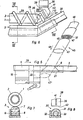
- the conveyor has a screw conveyor 1, the bead 2 of which runs directly over a slide rail.
- the slide rail consists of a plurality of rail sections which are arranged at intervals from one another and are connected to one another by connecting pieces.
- the garments hanging on hangers are fed to the end section 3 of the slide rail shown in FIG. 5, as described in more detail below.
- the clothes hanger hooks are then carried along by the screw 1 on the slide rail, of which the parts of two adjacent rail sections 4, 5 and the connecting piece 6 connecting them are shown in FIGS. 1 and 2.
- the rail sections and the connecting pieces consist of a round plastic profile 7, which stabilized by means of a C-metal profile 8 and mounted on an angle iron 9 (FIGS. 3 and 4).
- Each of the rail sections is welded with its angle iron 9 onto two bracket-shaped supports below. 1 to 3, one of the two carriers which support the rail section 4 is shown and designated 10.
- the carriers, which also carry bearing shells 11 for the screw 1, are fastened to a square iron 12 running over the entire rail track.
- the connecting piece 6 is trapezoidal in the horizontal longitudinal section and the ends 14, 15 of the rail sections 4, 5 connected by it are correspondingly wedge-shaped (FIG. 2).
- the wedge flanks 16, 17 of the rail section ends 14, 15 and the. converging surfaces 18, 19 of the connecting piece 6 run vertically.
- the angle iron 9 of the connector 6, the vertical leg in longitudinal section forming the longer base of the trapezoid, is attached to a longer, the angle iron 9 projecting at both ends, second angle iron 21, which in the illustrated rest position of the connector 6 on the angle iron 9 of the Rail sections 4 and 5 abuts.
- the part of the angle iron 21 which bears against the angle iron 9 of the rail section 4 is welded onto one end of a support 22 which is bow-shaped in cross section.
- An arm 23 is welded to the other end of the carrier 22 and is pivotally mounted about a vertical axis 24 fastened to the carrier 10.
- the piston rod 26 of a pneumatic cylinder 27 is articulated at the point designated at 25 on the other end of the girder, which is articulated on a bracket 28 attached to the girder 10.
- the double-acting pneumatic cylinder 27 and the corresponding pneumatic cylinders for the other connecting pieces are the compressed air feed controlling, common control device (not shown) controlled.
- the position in which the arm 23, the carrier 22 and the connecting piece 6 pivot when the pneumatic cylinder 27 is actuated is indicated by dash-dotted lines in FIG. 2.
- the wedge angle of the rail section ends 14, 15 be no more than 60 ° and in the example shown about 45 0th Since the clothes hanger hooks sliding on the slide rail are generally approximately at right angles to the rail track, this ensures that they do not abut one of the upper edges of the wedge surfaces 16, 17 or the converging surfaces 18, 19 even if the connecting piece 6 is not precise at the height of the rail sections 4, 5.
- a branch rail is assigned to each of the connecting pieces, with some of the branch rails being guided from one side and the remaining branch rails from the other side to the railroad track, so that magazines or processing stations for the conveyed goods can be set up on both sides of the railroad track and thus more Space for the individual magazines and stations is available.
- Each of the 3 and 4 right side (seen in the conveying direction 29 from the left side) brought to the railroad branch rails 45 (FIGS. 3 to 5) consists of a stationary pipe 46, on the upper part of which a pipe section 47, as by the Arrow 48 indicated, is slidably mounted.
- the tube 46 is located outside the conveying path of the necks 49 of the clothes hanger hooks 50 and runs in a vertical plane inclined to the rail track and inclined downward away from the rail track.
- a double-acting pneumatic cylinder 51 is arranged, the piston rod of which engages the tube piece 47 and pushes it during the feed stroke from the rest position shown in solid lines through the conveying path of the hook necks 49 into the position 47 'shown in broken lines below the connecting piece 6.
- the pneumatic cylinders 51 for the pipe sections 47 are controlled by the common control device (not shown), namely the pipe sections 47 are advanced when the associated connecting piece 6 is pivoted out of the railroad track, and retracted when that Connector 6 is pivoted back into the railroad.
- the branch rails brought up to the railroad track on the left in FIGS. 3 and 4 are not shown in the drawing. They each consist of a stationary tube, the free end of which is arranged under the associated connecting piece 6 and which is also inclined downward in a vertical plane which is at an angle to the railroad track.
- the inclination of these tubes and, accordingly, also the inclination of the tubes 46 is selected such that they come out of the railroad the connector 6 falling from the preceding rail section 4 onto the free end of the tube or the advanced tube section 47 'coat hook 50 falling down on the tube due to gravity.
- the clothes hangers are fed to the railroad in the manner described in more detail below, so that the open side of the hanger hook 50 lies to the left in the side view of FIGS. 3 and 4, because otherwise the hook neck 49 would strike the supports 10, 22.
- the hook necks 49 of the clothes hangers used for the device also have a minimum length which ensures that the hanger shoulders on which the items of clothing hang run at a distance below the supports 10, 22 of the rail sections and connecting pieces and under the upper parts of the branch rails.
- branch rails 45 like the branch rails 45, can be equipped with a displaceable pipe section 47, which is to be advanced so far that the neck 49 of the bracket hook 50 on it strikes, and the direction in which the branch rail leads away from the rail track is to be selected such that the bow hook 50 is turned in the direction of its conveying position on the branch rail when its neck 49 is struck.
- a displaceable pipe section 47 which is to be advanced so far that the neck 49 of the bracket hook 50 on it strikes, and the direction in which the branch rail leads away from the rail track is to be selected such that the bow hook 50 is turned in the direction of its conveying position on the branch rail when its neck 49 is struck.
- FIG. 6 shows the end section 3 of the rail track which, for reasons of space, is seen from the other side in the drawing in FIG. 6 than in FIG. 1, so that the conveying direction 29, in contrast to the illustration in FIGS. 1, 2 and 5 runs from right to left.
- an upwardly inclined feed rail 30 which, as shown in FIG. 8, consists of a plastic profile 31 which sits on a metal rod 33 welded to an angle iron 32.
- the plastic profile 31 and the rod 33 are longer than the angle iron 32 so that they can be bent into the position desired for the feed at the upper end.
- the angle of inclination of the feed rail 30 is selected such that the stirrups abandoned at its upper end slide down on it as a result of gravity.
- the worm 1 has a conically tapered end part 35 which projects beyond the end of the rail end section 3.
- the opening angle of the conical end part 35 is selected such that the respective lower surface line 36 of the conical worm core end runs parallel to the feed rail 30 and the worm bead 37 of the end part 35 directly above the feed rail 30 runs.
- a guide 38 is arranged above the feed rail 30 and consists of a T-profile, the flange 39 of which runs perpendicular to the rail 30.
- the end face 40 of the T-profile web 41 facing the rail is chamfered, that is to say more inclined than the feed rail 30.
- the two end faces 40, 42 form guide surfaces for those on the feed rail 30 clothes hanger hooks that slide down and prevent them from getting onto the screw 1 instead of underneath.
- the clothes hanger hooks thus guided under the conically tapered screw end part 35 are reliably carried along by the screw bead 37 because they slide into the bead curve 37 on the inclined feed rail 30 due to the force of gravity.
- the reliable and undelayed "infeed" of the items of clothing supplied at the end section 3, which is achieved in the manner described, is particularly important.
- the individual items of clothing are namely placed on the feed rail 30 one after the other at exactly the same time intervals.
- the task time, the type of the item of clothing and the branching point at which the item of clothing is to be branched off the railroad are stored in the memory of a microprocessor of the control device.
- the microprocessor uses the constant conveying speed of the device to calculate the point in time at which the item of clothing arrives at the desired branch point and acts directly on the pneumatic cylinder 27 of this branch point and, if the branch rail is equipped with a displaceable pipe section 47, also on the pneumatic cylinder 51.
- the connecting piece 6 of this branch point is pivoted out of the railroad track, the pipe piece 47 is advanced and the clothes hanger hook 50 falls on the pipe piece 47 or the upper part of the branch rail and slides on it either in a clothes container or a second conveyor, which conveys the garment to the target station, possibly via further branches and conveyors.
Landscapes
- Engineering & Computer Science (AREA)
- Mechanical Engineering (AREA)
- Chain Conveyers (AREA)
- Holders For Apparel And Elements Relating To Apparel (AREA)
- Intermediate Stations On Conveyors (AREA)
Applications Claiming Priority (2)
| Application Number | Priority Date | Filing Date | Title |
|---|---|---|---|
| CH2876/81 | 1981-05-04 | ||
| CH287681 | 1981-05-04 |
Publications (2)
| Publication Number | Publication Date |
|---|---|
| EP0064100A2 true EP0064100A2 (fr) | 1982-11-10 |
| EP0064100A3 EP0064100A3 (fr) | 1983-03-16 |
Family
ID=4243556
Family Applications (1)
| Application Number | Title | Priority Date | Filing Date |
|---|---|---|---|
| EP81110481A Withdrawn EP0064100A3 (fr) | 1981-05-04 | 1981-12-16 | Dispositif de transport pour des objets pendus en crochets, notamment pour vêtements pendus en ceintres |
Country Status (1)
| Country | Link |
|---|---|
| EP (1) | EP0064100A3 (fr) |
Cited By (2)
| Publication number | Priority date | Publication date | Assignee | Title |
|---|---|---|---|---|
| EP0336714A3 (fr) * | 1988-04-05 | 1990-11-22 | Stockrail International Limited | Systèmes d'entrepôt |
| RU2102303C1 (ru) * | 1991-08-12 | 1998-01-20 | Франц Гэртнер | Способ сортировки одежды, подвешенной на крюках, и устройство для его осуществления |
-
1981
- 1981-12-16 EP EP81110481A patent/EP0064100A3/fr not_active Withdrawn
Non-Patent Citations (1)
| Title |
|---|
| None * |
Cited By (2)
| Publication number | Priority date | Publication date | Assignee | Title |
|---|---|---|---|---|
| EP0336714A3 (fr) * | 1988-04-05 | 1990-11-22 | Stockrail International Limited | Systèmes d'entrepôt |
| RU2102303C1 (ru) * | 1991-08-12 | 1998-01-20 | Франц Гэртнер | Способ сортировки одежды, подвешенной на крюках, и устройство для его осуществления |
Also Published As
| Publication number | Publication date |
|---|---|
| EP0064100A3 (fr) | 1983-03-16 |
Similar Documents
| Publication | Publication Date | Title |
|---|---|---|
| DE3738448C2 (de) | Fördereinrichtung zur Überführung von Schlachtgeflügel in Hängeposition zu einer Geflügelbehandlungsstation, wie einer Verpackungseinrichtung | |
| DE69723000T2 (de) | Bearbeitung von geflügel mit karkassen-stabilisator | |
| DE3531550C2 (fr) | ||
| DE9207217U1 (de) | Hängefördervorrichtung mit Abwurfstangenübergabeeinrichtung | |
| DE9217954U1 (de) | Vorrichtung zum Sortieren von an Haken hängendem Gut | |
| DE69109122T2 (de) | Verfahren und anordnung zum vorbereiten einer verpackten substanz zum räuchern und/oder einer anderen behandlung. | |
| DE69406276T2 (de) | Verfahren zur aufhängung von lebendem geflügel an den füssen und vorrichtung zur durchführung dieses verfahrens | |
| DE2310356A1 (de) | Foerdergestell | |
| US3380113A (en) | Poultry shackle unloading device | |
| DE2537442C2 (de) | Umladevorrichtung an Hängebahnen | |
| EP0512266B1 (fr) | Convoyeur aérien pour des marchandises transportées sur cintres | |
| DE3024195A1 (de) | Foerdersystem zum hindurchfuehren von werkstuecken durch fluessigkeitsbehandlungsbaeder | |
| EP0456051B1 (fr) | Procédé et dispositif d'amenée de pièces de linge à un appareil de traitement, notamment un dispositif automatique de pliage | |
| DE60126260T2 (de) | Verfahren und vorrichtung zum aufhängen von schlachttieren, insbesondere von geflügel | |
| DE3011026C2 (de) | Anlage zum Zerlegen von an einem Hängefördermittel zu einem Fleischauslöseplatz geförderten Schlachttierkörpern | |
| DE2924110A1 (de) | Vorrichtung zum transport von mit aufhaengeoesen versehenen massenguetern | |
| DE2001932A1 (de) | Vorrichtung zum Transportieren von Stranggut | |
| DE29809909U1 (de) | Klinken-Sortierförderer | |
| DE2557877B2 (de) | Vorrichtung zum abnehmen und aufgeben von schlachtgefluegel von bzw. auf transportbahnen | |
| DE3802806C1 (en) | Label-suspension apparatus | |
| EP0403865B1 (fr) | Dispositif de transfert pour les produits d'un transporteur aérien interne | |
| DE2314204C3 (de) | Transportvorrichtung für in Behälter oder Bäder zu tauchende Werkstücke | |
| DE3119238A1 (de) | Aufhaengevorrichtung fuer fleischprodukte | |
| DE3901870C2 (fr) | ||
| DE1506927C (de) | Entladevorrichtung in einem Kreis förderer |
Legal Events
| Date | Code | Title | Description |
|---|---|---|---|
| PUAI | Public reference made under article 153(3) epc to a published international application that has entered the european phase |
Free format text: ORIGINAL CODE: 0009012 |
|
| AK | Designated contracting states |
Designated state(s): AT CH DE FR LI NL SE |
|
| PUAL | Search report despatched |
Free format text: ORIGINAL CODE: 0009013 |
|
| AK | Designated contracting states |
Designated state(s): AT CH DE FR LI NL SE |
|
| RHK1 | Main classification (correction) |
Ipc: B65G 33/04 |
|
| STAA | Information on the status of an ep patent application or granted ep patent |
Free format text: STATUS: THE APPLICATION IS DEEMED TO BE WITHDRAWN |
|
| 18D | Application deemed to be withdrawn |
Effective date: 19840224 |
|
| RIN1 | Information on inventor provided before grant (corrected) |
Inventor name: GRAESSLE, VOLKER |