EP0064128A2 - Fühler für elektronisches Medizinalthermometer - Google Patents
Fühler für elektronisches Medizinalthermometer Download PDFInfo
- Publication number
- EP0064128A2 EP0064128A2 EP82100824A EP82100824A EP0064128A2 EP 0064128 A2 EP0064128 A2 EP 0064128A2 EP 82100824 A EP82100824 A EP 82100824A EP 82100824 A EP82100824 A EP 82100824A EP 0064128 A2 EP0064128 A2 EP 0064128A2
- Authority
- EP
- European Patent Office
- Prior art keywords
- probe
- temperature
- members
- tubular members
- cup
- Prior art date
- Legal status (The legal status is an assumption and is not a legal conclusion. Google has not performed a legal analysis and makes no representation as to the accuracy of the status listed.)
- Withdrawn
Links
Images

Classifications
-
- G—PHYSICS
- G01—MEASURING; TESTING
- G01K—MEASURING TEMPERATURE; MEASURING QUANTITY OF HEAT; THERMALLY-SENSITIVE ELEMENTS NOT OTHERWISE PROVIDED FOR
- G01K1/00—Details of thermometers not specially adapted for particular types of thermometer
- G01K1/16—Special arrangements for conducting heat from the object to the sensitive element
- G01K1/18—Special arrangements for conducting heat from the object to the sensitive element for reducing thermal inertia
Definitions
- This invention relates generally to clinical electronic thermometers for measuring body temperature through the use of a probe. More particularly, it relates to an imnroved probe construction which is sealed, sanitary and has low thermal mass for quick response of the temperature-responsive element.
- Probes for use with associated electrical circuitry for the measurement of body temperature and display of the temperature are well known. The majority of commercial devices are divided into two different types. One is based upon a thermistor element in the end of the probe which changes its resistance with temperature. A basic probe of this type is shown in U.S. Patent 3,025,706 - Oppenheim. The other type of probe which has been suggested for an electronic clinical thermometer is a thermocouple type probe, as exemplified in U.S. Patent 4,174,631 issued November 20, 1979 to Hammerslag. There are probes on the market with probe bodies comprising open-ended inner and outer coaxial tubular members having low thermal conductivity and with thin walls of low thermal mass.
- thermometer device When any thermometer device is inserted, it locally cools the tissues, since the thermometer temperature is initially below body temperature. The time required to recover from this effect due to the interaction between the probe and the body is dependent not only on the probe design, but also on the blood circulation and other thermal characteristics of the tissue. The time required for a conventional glass clinical thermometer to reach final tissue temperature is in the neighborhood of 3 to 5 minutes. The primary factor determining this time lag is the thermal mass of the thermometer, which must be brought into substantial correspondence with the local tissue temperature. The local temperature of the tissue must itself also be brought back to where it was before the thermometer was inserted, due to its being cooled down by the thermometer.
- Probe preheaters have been employed with thermistors to speed the response by raising the local temperature of the probe in the vicinity of the thermistor, as disclosed in the aforementioned patent to Oppenheim, as well as many other patents exemplified by the following:
- thermocouple probes have been usually favored for clinical thermometers over thermocouple probes, because the electrical circuitry is simpler and because there is no need for a reference temperature or compensation for the cold junction as there is in a thermocouple probe.
- Normally thermocouples have been used for temperature sensing devices measuring relatively high temperatures c/er a wide temperature range. This is because the voltage generated is a function of the difference between the hot junction and the cold junction, which favors a large temperature difference.
- thermocouple probes are now also practical for clinical temperature measurement.
- thermocouple probe of low thermal mass achieved by supporting the thermal couple leads in a hollow tube of plastic material and causing the thermocouple junction to bridge the open end of the tube, so that the thin thermocouples support wires and junction are exposed for direct contact with the tissue of a patient.
- thermocouple leads since the thermocouple leads are exposed, they may be subject to damage. Also because of the open end of the tube, the probe may become unsanitary due to entry of saliva or foreign matter.
- Another type of probe with exposed leads is shown in U.S. Patent 4,250,751 issued February 17, 1981 to Holzhacker et.al.
- one object of the present invention is to provide an improved probe suitable for clinical electronic temperature measurement.
- Another object of the invention is to provide an improved probe having a temperature-responsive element and probe body of very low thermal mass and improved speed of response.
- Another object of the invention is to provide an improved construction for an inexpensive probe for a clinical electronic thermometer.
- the invention is practiced by providing improvements in a probe having thin coaxial tubular members of low thermal conductivity supporting lead conductors, said improvements comprising at least one substantially hemispherical cup member of low thermal mass closing the end of the probe and sealed to the ends of the tubular members, and a temperature responsive element supported on said hemispherical cup member and connected to the leads.
- a temperature responsive element supported on said hemispherical cup member and connected to the leads.
- the probe is shown associated with a carrying case 1 which also houses the battery and elec- troni c circuitry (not shown), operating switch 2 and a display 3 adapted to give a reading indication of the body temperature measured by the probe.
- the probe itself includes a handle 4 adapted to nest in the carrying case, a connecting spring-coil cord 5 attaching the internal circuitry with the thermocouple leads in the probe body 6 connected to the handle 4.
- Probe body 6 may be a permanent part of handle 4 or preferably is adapted for detaching from handle 4 for replacement with another probe. The method of attachment is not material to the present invention.
- the probe When the probe is not in use, it and the coil cord are stored in the housing 1.
- a suitable arrangement for storing the probe and cord are disclosed in my copending application Serial No. 249,760 for an improved "Electronic Thermometer with Integrally Housed Probe and Coil Cord" filed on April 1, 1981 and assigned to the present assignee.
- probe body 6 is comprised of an outer tubular member 7, a coaxial inner tubular member 8 carrying between them first and second leads 9, 10 leading to a temperature-responsive element 11.
- the outer tubular members 7, 8 are selected from material which has as low thermal conductivity as possible, in order to minimize the transfer of heat from the tip of the probe toward the handle. Thermal conductivities on the order of .0006 cal/sec/cm/sq. cm/deg. C or less are used. Many plastic materials are suitable for this purpose, one suitable material being cellulose acetate.
- the tubular members 7, 8 are made as thin as possible to reduce their thermal mass.
- the wall thickness used will depend somewhat upon whether the probe is intended to be disposable or not. Wall thickness on the order of 0.1mm are suitable for disposable probes while greater wall thicknesses may be preferable for a permanent probe.
- the leads 9, 10 are likewise selected to be of very low thermal mass. In the preferred embodiment, leads with diameters on the order of 0.1mm have been found suitable.
- the temperature-responsive element 11 may comprise a thermocouple junction 11 of low thermal mass.
- the thermocouple metals may vary with the application but a suitable probe has been constructed using a type E thermocouple with a lead combination of Chromel-Constantan. In the case of thermocouple, the leads 9, 10 are, therefore, of dissimilar metals.
- a thermistor may be used as the temperature-responsive element 11.
- a suitable,thermistor is commercially available and comprises a small wafer with a volume less than 0.5 cubic millimeters, commercially obtainable from Gulton Industries.
- the thermistor can also be applied as a thin film.
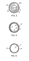
- FIG. 5 is a cross-section through the tubular members in the portion of the probe body connecting the probe tip to the handle shows that the tubular members conveniently support and insulate the very fragile leads 9, 10 between them, preferably in diametrically opposed locations as shown.
- lead portions designated 9a and 10a extending between the ends of the tubular members and the temperature-responsive element 11, as well as element 11 itself, are supported and protected by at least one substantially hemispherical cup member attached to and sealed to the ends of the tubular members.
- an outer hemispherical cup member 12 and a concentric inner hemispherical cup member 13 support the lead portions 9a, 10a and element 11 between them.
- Cups 12, 13 also serve to seal off the ends of the tubular members and prevent the entry of any foreign matter.
- Reference to Fig. 3 shows an end view of the probe end with the portion of the outer hemispherical cup member 12 broken away to illustrate how the leads are fully supported along the surface of the cup members.
- the thermal conductivity of the material for cup members 12, 13 is not as critical as it is for the tubular members, since it is desirable to ensure that some averaging of local temperature variations in the vicinity of the thermocouple junction take place.
- the cup members may either be of plastic material, this being convenient since it also serves as an insulator, or can be of metal with a thin insulating coating.
- a suitable material is polycarbonate.
- the cup members 12, 13 be of low thermal mass while providing sufficient rigidity to support the fragile leads.
- the thickness of the cup members should be no greater than about 0.15mm thick, but preferably on the order of 0.05 to 0.08mm.
- the filling material should not significantly increase the thermal mass.
- a hemispherical shape is preferred to carry out this function.
- “hemispherical” Includes also in its meaning shapes which approximately a hemispherical shape, such as truncated conical or parabolic shapes.
- the lower ends of the cups 12, 13 are provided with depending cylindrical skirt portion 12a, 13a, respectively.
- the skirt portions of the cup members are preferably sealed beween the inner and outer tubular members as indicated in Fig. 2.
- FIG. 4 shows the cross-section through the cups and tubes.
- An adhesive sealant is employed in all the spaces between members 7, 8, 12, 13.
- a suitable sealant for this purpose is silicone rubber sealant.
- the above-described probe of low thermal mass provides a clean sanitary probe construction suitable for a clinical thermometer and having a fast response.
- a typical time constant obtained using the probe described above with a thermocouple junction is under 1 second, allowing a body temperature reading to be reached in about 3 to 5 seconds which is within 0.1°F accuracy of the initial tissue temperature.
- the time constant is around 2 to 3 seconds allowing a body temperature reading to be reached in about 10 to 15 seconds. With thin film thermistors, these latter times may be improved.
Landscapes
- Physics & Mathematics (AREA)
- General Physics & Mathematics (AREA)
- Measuring Temperature Or Quantity Of Heat (AREA)
- Measuring And Recording Apparatus For Diagnosis (AREA)
Applications Claiming Priority (4)
| Application Number | Priority Date | Filing Date | Title |
|---|---|---|---|
| US24977981A | 1981-04-01 | 1981-04-01 | |
| US249779 | 1981-04-01 | ||
| US309667 | 1981-10-08 | ||
| US06/309,667 US4411535A (en) | 1981-04-01 | 1981-10-08 | Probe for clinical electronic thermometer |
Publications (2)
| Publication Number | Publication Date |
|---|---|
| EP0064128A2 true EP0064128A2 (de) | 1982-11-10 |
| EP0064128A3 EP0064128A3 (de) | 1983-04-20 |
Family
ID=26940341
Family Applications (1)
| Application Number | Title | Priority Date | Filing Date |
|---|---|---|---|
| EP82100824A Withdrawn EP0064128A3 (de) | 1981-04-01 | 1982-02-05 | Fühler für elektronisches Medizinalthermometer |
Country Status (2)
| Country | Link |
|---|---|
| US (1) | US4411535A (de) |
| EP (1) | EP0064128A3 (de) |
Families Citing this family (25)
| Publication number | Priority date | Publication date | Assignee | Title |
|---|---|---|---|---|
| DE3300733A1 (de) * | 1983-01-12 | 1984-07-12 | Robert Bosch Gmbh, 7000 Stuttgart | Temperaturfuehler |
| US4487208A (en) * | 1983-01-21 | 1984-12-11 | Timex Medical Products Corporation | Fast response thermoresistive temperature sensing probe |
| US4728369A (en) * | 1985-04-03 | 1988-03-01 | Hammerslag Julius G | Thermocouple probes |
| JPS629239A (ja) * | 1985-07-05 | 1987-01-17 | Omron Tateisi Electronics Co | 高速応答型温度センサ |
| US5199789A (en) * | 1990-11-19 | 1993-04-06 | Mauric Stanley J | Immersion well assembly |
| US5725308A (en) * | 1994-12-23 | 1998-03-10 | Rtd Technology, Inc. | Quick registering thermometer |
| JP2000111414A (ja) | 1998-10-09 | 2000-04-21 | Hyakuryaku Kigyo Kofun Yugenkoshi | 医療体温計 |
| JP2003503693A (ja) * | 1999-06-23 | 2003-01-28 | エリアフ ルビンスタイン、 | 熱警報システム |
| US6338571B1 (en) * | 2000-02-03 | 2002-01-15 | Min-Ying Chen | Rapid heat conducting structure of an electronic thermometer |
| US6773405B2 (en) | 2000-09-15 | 2004-08-10 | Jacob Fraden | Ear temperature monitor and method of temperature measurement |
| US6839651B2 (en) | 2001-06-27 | 2005-01-04 | Sherwood Services Ag | Probe tip thermal isolation and fast prediction algorithm |
| US20030198278A1 (en) * | 2002-01-18 | 2003-10-23 | Chu-Yih Yu | Thermometer having a disposable temperature probe |
| TW557352B (en) * | 2002-10-07 | 2003-10-11 | Actherm Inc | Electronic clinical thermometer with rapid response |
| US6971790B2 (en) * | 2002-10-11 | 2005-12-06 | Welch Allyn, Inc. | Thermometry probe calibration method |
| US7785266B2 (en) | 2003-08-19 | 2010-08-31 | Advanced Monitors Corporation | Medical thermometer for determining body core temperature |
| US7938783B2 (en) | 2003-08-19 | 2011-05-10 | Advanced Monitors Corporation | Medical body core thermometer |
| TW593993B (en) * | 2003-11-03 | 2004-06-21 | Oriental System Technology Inc | Electrical thermometer |
| US7806587B2 (en) * | 2004-09-29 | 2010-10-05 | Citizen Holdings Co., Ltd. | Electronic clinical thermometer and method of producing the same |
| US7316507B2 (en) * | 2005-11-03 | 2008-01-08 | Covidien Ag | Electronic thermometer with flex circuit location |
| US20070100253A1 (en) * | 2005-11-03 | 2007-05-03 | Sherwood Services Ag | Electronic thermometer with sensor location |
| US7561982B2 (en) * | 2005-11-10 | 2009-07-14 | Shake Awake Products, LLC | Physical attribute recording method and system |
| US7749170B2 (en) * | 2007-05-22 | 2010-07-06 | Tyco Healthcare Group Lp | Multiple configurable electronic thermometer |
| US8496377B2 (en) | 2007-12-31 | 2013-07-30 | Covidien Lp | Thermometer having molded probe component |
| US8794829B2 (en) * | 2009-12-31 | 2014-08-05 | Welch Allyn, Inc. | Temperature-measurement probe |
| TWM407044U (en) * | 2010-11-19 | 2011-07-11 | Mesure Technology Co Ltd | Thermometer with a hollow heat conductive structure |
Family Cites Families (11)
| Publication number | Priority date | Publication date | Assignee | Title |
|---|---|---|---|---|
| US2186707A (en) * | 1939-02-08 | 1940-01-09 | William A Ray | Thermocouple structure |
| US3006978A (en) * | 1958-11-14 | 1961-10-31 | North American Aviation Inc | High temperature thin film thermocouple |
| US3570312A (en) * | 1968-06-21 | 1971-03-16 | Frank Kreith | Skin temperature sensing device |
| US4022063A (en) * | 1974-10-15 | 1977-05-10 | Rwb Labs | Electromechanical digital thermometer |
| FR2339164A1 (fr) * | 1976-01-23 | 1977-08-19 | Louyot Comptoir Lyon Alemand | Appareil emaille de mesure de la temperature d'un fluide comportant un couple thermoelectrique |
| US4054057A (en) * | 1976-03-01 | 1977-10-18 | Diatek, Inc. | Temperature sensing probe and disposable cover therefor |
| US4142170A (en) * | 1977-12-05 | 1979-02-27 | The Bendix Corporation | High response temperature sensor |
| US4174631A (en) * | 1978-01-09 | 1979-11-20 | Temp-Stik Corporation | Clinical thermometer with thermo-couple probe |
| US4183248A (en) * | 1978-08-08 | 1980-01-15 | Rwb Labs | Fast response electronic thermometer probe |
| US4251908A (en) * | 1979-01-15 | 1981-02-24 | The United States Of America As Represented By The United States Department Of Energy | Side-welded fast response sheathed thermocouple |
| NL8000443A (nl) * | 1980-01-23 | 1981-08-17 | Schmidt Arthur O F J | Temperatuurmeetinrichting. |
-
1981
- 1981-10-08 US US06/309,667 patent/US4411535A/en not_active Expired - Fee Related
-
1982
- 1982-02-05 EP EP82100824A patent/EP0064128A3/de not_active Withdrawn
Also Published As
| Publication number | Publication date |
|---|---|
| US4411535A (en) | 1983-10-25 |
| EP0064128A3 (de) | 1983-04-20 |
Similar Documents
| Publication | Publication Date | Title |
|---|---|---|
| US4411535A (en) | Probe for clinical electronic thermometer | |
| US4487208A (en) | Fast response thermoresistive temperature sensing probe | |
| US4457633A (en) | Temperature probe cover | |
| EP1857795B1 (de) | Trommelfellthermometer | |
| US7841767B2 (en) | Thermal tympanic thermometer | |
| US6419388B2 (en) | Medical thermometer | |
| US3531992A (en) | Expendable tympanic membrane thermometer | |
| US4595020A (en) | Disposable probe for temperature measurements in humans | |
| US6220750B1 (en) | Non-invasive temperature measurement method and apparatus | |
| US8123401B2 (en) | Probe cover having a blackbody | |
| JP2001502953A (ja) | 腋下赤外線体温計およびその使用方法 | |
| US3663917A (en) | Disposable temperature-sensing device | |
| JPS5937773B2 (ja) | 温度検出装置 | |
| US20120128031A1 (en) | Electronic Clinical Thermometer | |
| CN213301522U (zh) | 一种具有硅胶探头的体温计 | |
| US4560287A (en) | Safety case for the medical glass thermometer | |
| RU2029928C1 (ru) | Устройство для измерения температуры поверхности объекта | |
| EP1119750B1 (de) | Medizinisches thermometer | |
| US3727461A (en) | Disposable plastic thermometer | |
| IL155352A (en) | Non-invasive electronic thermometer | |
| JPH0328351Y2 (de) | ||
| JPH0241698B2 (de) | ||
| JP2022044068A (ja) | 透明な断熱体を含む哺乳瓶用温度計 | |
| JPS63176536A (ja) | 尿体温計 | |
| AU2007200873A1 (en) | Thermal tympanic thermometer tip |
Legal Events
| Date | Code | Title | Description |
|---|---|---|---|
| PUAI | Public reference made under article 153(3) epc to a published international application that has entered the european phase |
Free format text: ORIGINAL CODE: 0009012 |
|
| AK | Designated contracting states |
Designated state(s): BE CH DE FR GB IT NL SE |
|
| PUAL | Search report despatched |
Free format text: ORIGINAL CODE: 0009013 |
|
| AK | Designated contracting states |
Designated state(s): BE CH DE FR GB IT LI NL SE |
|
| STAA | Information on the status of an ep patent application or granted ep patent |
Free format text: STATUS: THE APPLICATION IS DEEMED TO BE WITHDRAWN |
|
| 18D | Application deemed to be withdrawn |
Effective date: 19840102 |
|
| RIN1 | Information on inventor provided before grant (corrected) |
Inventor name: SCHWARZSCHILD, JACK |