EP0064151A1 - Accouplement pour arbre - Google Patents
Accouplement pour arbre Download PDFInfo
- Publication number
- EP0064151A1 EP0064151A1 EP82102319A EP82102319A EP0064151A1 EP 0064151 A1 EP0064151 A1 EP 0064151A1 EP 82102319 A EP82102319 A EP 82102319A EP 82102319 A EP82102319 A EP 82102319A EP 0064151 A1 EP0064151 A1 EP 0064151A1
- Authority
- EP
- European Patent Office
- Prior art keywords
- compound according
- membrane
- fvw
- blanks
- connection
- Prior art date
- Legal status (The legal status is an assumption and is not a legal conclusion. Google has not performed a legal analysis and makes no representation as to the accuracy of the status listed.)
- Withdrawn
Links
- 238000010168 coupling process Methods 0.000 title claims abstract description 11
- 238000005859 coupling reaction Methods 0.000 title claims abstract description 11
- 230000008878 coupling Effects 0.000 title claims abstract description 8
- 239000012528 membrane Substances 0.000 claims abstract description 38
- 239000000835 fiber Substances 0.000 claims abstract description 12
- 239000002131 composite material Substances 0.000 claims abstract description 9
- 239000004744 fabric Substances 0.000 claims description 8
- 230000002787 reinforcement Effects 0.000 claims description 4
- 238000000034 method Methods 0.000 claims description 2
- 230000007704 transition Effects 0.000 claims description 2
- 150000001875 compounds Chemical class 0.000 claims 14
- 238000005516 engineering process Methods 0.000 claims 2
- 239000000463 material Substances 0.000 claims 2
- 239000000853 adhesive Substances 0.000 claims 1
- 230000001070 adhesive effect Effects 0.000 claims 1
- 230000002457 bidirectional effect Effects 0.000 claims 1
- 238000009730 filament winding Methods 0.000 claims 1
- 238000003475 lamination Methods 0.000 claims 1
- 239000012779 reinforcing material Substances 0.000 claims 1
- 238000002791 soaking Methods 0.000 claims 1
- 230000001105 regulatory effect Effects 0.000 abstract 1
- 210000004379 membrane Anatomy 0.000 description 30
- 230000005540 biological transmission Effects 0.000 description 3
- 229920000271 Kevlar® Polymers 0.000 description 2
- 238000005452 bending Methods 0.000 description 2
- 230000000694 effects Effects 0.000 description 2
- 239000004761 kevlar Substances 0.000 description 2
- 238000004519 manufacturing process Methods 0.000 description 2
- 239000011159 matrix material Substances 0.000 description 2
- 239000011265 semifinished product Substances 0.000 description 2
- 238000009827 uniform distribution Methods 0.000 description 2
- 241001136792 Alle Species 0.000 description 1
- 229920000049 Carbon (fiber) Polymers 0.000 description 1
- 229910000831 Steel Inorganic materials 0.000 description 1
- 239000004760 aramid Substances 0.000 description 1
- 229920006231 aramid fiber Polymers 0.000 description 1
- 239000004917 carbon fiber Substances 0.000 description 1
- 238000010276 construction Methods 0.000 description 1
- 238000005520 cutting process Methods 0.000 description 1
- 238000006073 displacement reaction Methods 0.000 description 1
- 239000003365 glass fiber Substances 0.000 description 1
- 238000009434 installation Methods 0.000 description 1
- 238000012423 maintenance Methods 0.000 description 1
- 238000005457 optimization Methods 0.000 description 1
- 239000012783 reinforcing fiber Substances 0.000 description 1
- 230000003068 static effect Effects 0.000 description 1
- 239000010959 steel Substances 0.000 description 1
- 238000003860 storage Methods 0.000 description 1
- 239000002699 waste material Substances 0.000 description 1
Images

Classifications
-
- B—PERFORMING OPERATIONS; TRANSPORTING
- B29—WORKING OF PLASTICS; WORKING OF SUBSTANCES IN A PLASTIC STATE IN GENERAL
- B29C—SHAPING OR JOINING OF PLASTICS; SHAPING OF MATERIAL IN A PLASTIC STATE, NOT OTHERWISE PROVIDED FOR; AFTER-TREATMENT OF THE SHAPED PRODUCTS, e.g. REPAIRING
- B29C70/00—Shaping composites, i.e. plastics material comprising reinforcements, fillers or preformed parts, e.g. inserts
- B29C70/04—Shaping composites, i.e. plastics material comprising reinforcements, fillers or preformed parts, e.g. inserts comprising reinforcements only, e.g. self-reinforcing plastics
- B29C70/28—Shaping operations therefor
- B29C70/30—Shaping by lay-up, i.e. applying fibres, tape or broadsheet on a mould, former or core; Shaping by spray-up, i.e. spraying of fibres on a mould, former or core
- B29C70/34—Shaping by lay-up, i.e. applying fibres, tape or broadsheet on a mould, former or core; Shaping by spray-up, i.e. spraying of fibres on a mould, former or core and shaping or impregnating by compression, i.e. combined with compressing after the lay-up operation
- B29C70/345—Shaping by lay-up, i.e. applying fibres, tape or broadsheet on a mould, former or core; Shaping by spray-up, i.e. spraying of fibres on a mould, former or core and shaping or impregnating by compression, i.e. combined with compressing after the lay-up operation using matched moulds
-
- B—PERFORMING OPERATIONS; TRANSPORTING
- B61—RAILWAYS
- B61F—RAIL VEHICLE SUSPENSIONS, e.g. UNDERFRAMES, BOGIES OR ARRANGEMENTS OF WHEEL AXLES; RAIL VEHICLES FOR USE ON TRACKS OF DIFFERENT WIDTH; PREVENTING DERAILING OF RAIL VEHICLES; WHEEL GUARDS, OBSTRUCTION REMOVERS OR THE LIKE FOR RAIL VEHICLES
- B61F3/00—Types of bogies
- B61F3/16—Types of bogies with a separate axle for each wheel
-
- F—MECHANICAL ENGINEERING; LIGHTING; HEATING; WEAPONS; BLASTING
- F16—ENGINEERING ELEMENTS AND UNITS; GENERAL MEASURES FOR PRODUCING AND MAINTAINING EFFECTIVE FUNCTIONING OF MACHINES OR INSTALLATIONS; THERMAL INSULATION IN GENERAL
- F16D—COUPLINGS FOR TRANSMITTING ROTATION; CLUTCHES; BRAKES
- F16D3/00—Yielding couplings, i.e. with means permitting movement between the connected parts during the drive
- F16D3/50—Yielding couplings, i.e. with means permitting movement between the connected parts during the drive with the coupling parts connected by one or more intermediate members
- F16D3/72—Yielding couplings, i.e. with means permitting movement between the connected parts during the drive with the coupling parts connected by one or more intermediate members with axially-spaced attachments to the coupling parts
- F16D3/725—Yielding couplings, i.e. with means permitting movement between the connected parts during the drive with the coupling parts connected by one or more intermediate members with axially-spaced attachments to the coupling parts with an intermediate member made of fibre-reinforced resin
-
- F—MECHANICAL ENGINEERING; LIGHTING; HEATING; WEAPONS; BLASTING
- F16—ENGINEERING ELEMENTS AND UNITS; GENERAL MEASURES FOR PRODUCING AND MAINTAINING EFFECTIVE FUNCTIONING OF MACHINES OR INSTALLATIONS; THERMAL INSULATION IN GENERAL
- F16D—COUPLINGS FOR TRANSMITTING ROTATION; CLUTCHES; BRAKES
- F16D3/00—Yielding couplings, i.e. with means permitting movement between the connected parts during the drive
- F16D3/50—Yielding couplings, i.e. with means permitting movement between the connected parts during the drive with the coupling parts connected by one or more intermediate members
- F16D3/76—Yielding couplings, i.e. with means permitting movement between the connected parts during the drive with the coupling parts connected by one or more intermediate members shaped as an elastic ring centered on the axis, surrounding a portion of one coupling part and surrounded by a sleeve of the other coupling part
-
- B—PERFORMING OPERATIONS; TRANSPORTING
- B29—WORKING OF PLASTICS; WORKING OF SUBSTANCES IN A PLASTIC STATE IN GENERAL
- B29L—INDEXING SCHEME ASSOCIATED WITH SUBCLASS B29C, RELATING TO PARTICULAR ARTICLES
- B29L2031/00—Other particular articles
- B29L2031/727—Fastening elements
- B29L2031/7278—Couplings, connectors, nipples
Definitions
- the invention relates to a shaft coupling connection according to the preamble of claim 1.
- a so-called slip-controlled wheel attachment has been developed for rail vehicles to increase the critical speed while reducing wear (see, for example, DE-PS 28 48 398), the running of which is stabilized by a controlled transfer of elements between the wheels.
- the wheels are connected to the slip clutch located in the center of the axle via one of the hollow shafts, whereby between the Hollow shafts and the coupling each have a separate shaft-coupling connection must be provided.
- claim 3 has the particular advantage that the actual power transmission (through the elements preferably provided according to claim 4) takes place via the reveal, that is to say in a form-fitting manner, since the frictional engagement normally required for a screw connection depends on the pretensioning force of the screws. But leaves after this biasing force possible, due K smelling of fiber composite material, the reliable transmission of forces could be called into question.
- the membrane is glued to the hollow shaft according to claim 19, since it does not have to be releasably attached to the hollow shaft, so that a saving in space and effort compared to screws with bores and possibly fitting bolts or the like is achieved.
- the teaching of claim 20 has the particular advantage that the laying technique for the membrane, which can no longer be unwound due to the conical tube attachment, is more manageable.
- the embankment stress is kept low.
- F ig. 1 shows one half of a slip-controlled wheel set, namely a disc wheel . 1, which is mounted on a fixed axis 3 via a bearing 2.
- a hollow shaft 4 is connected to the disk wheel 1, which in turn is connected to a clutch 10 via an FVW membrane 20 in a manner to be explained.
- the schematically indicated clutch 10 has two rotating clutch parts 12 and 14, the rotating clutch part 14 being connected to the other disk wheel (not shown).
- the clutch 10 has bearings 13a and 13b and a stator 16 which electromagnetically effects the engagement of the two rotating clutch parts 14 and 16.
- the fiber-composite membrane 20 has a one-piece, slightly conical pipe socket 24 which is inserted into the hollow shaft 4 and ser connected to DIE 'by a schematically indicated bonding 38, as well as a reinforcement 22 at its outer edge, the reinforcement 22 is connected to the rotating coupling part 12 are connected by fitting bolt 32 and screws 34 with spring ring 36 and by an additional outer ring 30, as ig readily from F. 1 can be seen. In fact, several such connecting elements are provided, as required.
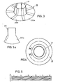
- FIG. 2 shows a flat, namely annular FVW membrane 20 (ie without a one-piece, slightly conical tube extension 24 as in FIG. 1) made of several partial blanks such as 20a and 20b with radial fiber orientation P, the partial blanks being semi-finished products made of unidirectional prepreg, warp-reinforced fabric or the like.
- the part-blanks are joined at .Überlappept 21, from the same kind as in F ig in section. 5 shown as overlaps 300.
- Fig. 3 shows, in contrast to FIG. 2, where the FVW membrane is flat, namely circular, an FVW membrane 20 with a one-piece, slightly conical tube extension 24 - similar as in Fig. 1 -, wherein the membrane is composed of overlapping partial blanks such as 200a and 200b.
- the overlaps 201 have the same structure as in FIG. 5 shown.
- Fig. 3 only a single laminate layer of the FVW membrane 20 is shown, in fact the membrane consists of several such layers, which are each composed of several partial blanks such as 200a and 200b.
- F i g. 4 shows, similar to FIG. 3, an FVW membrane 20 with a one-piece, slightly conical tube extension 24.
- F i g. 5 shows in more detail the individual laminate layers a - f, which in turn are each composed of partial blanks I - VI.
- the individual layers a - f are rotated against one another in order to achieve a uniform distribution of the overlap joints 300 of the partial blanks I - VI.
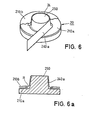
- F i g. 6 shows a last exemplary embodiment of an FVW membrane 20 with a one-piece, slightly conical tube extension 24.
- circular blanks such as 210a and 210b, in particular prepreg or fabric, which form different annular layers, and strip-shaped blanks are successively formed around a mold (positive part) 250 applied as 240a, as can be seen directly from FIG. 6, in particular its (lower) sectional view.
- strip-shaped blanks such as 240a which can also consist of prepreg or fabric, are slightly bulged at the lower edge, so that they are at the transition radius R between the circular ring formed by the circular cuts such as 210a and 210b and the connection to the strip-shaped sections 240a formed conical tube extension 24 overlap, as can also be clearly seen from the sectional view of FIG. 6.
Landscapes
- Engineering & Computer Science (AREA)
- Mechanical Engineering (AREA)
- General Engineering & Computer Science (AREA)
- Chemical & Material Sciences (AREA)
- Composite Materials (AREA)
- Moulding By Coating Moulds (AREA)
Applications Claiming Priority (2)
| Application Number | Priority Date | Filing Date | Title |
|---|---|---|---|
| DE3117126 | 1981-04-30 | ||
| DE19813117126 DE3117126C2 (de) | 1981-04-30 | 1981-04-30 | Wellenkupplung mit einer elastischen Membran |
Publications (1)
| Publication Number | Publication Date |
|---|---|
| EP0064151A1 true EP0064151A1 (fr) | 1982-11-10 |
Family
ID=6131158
Family Applications (1)
| Application Number | Title | Priority Date | Filing Date |
|---|---|---|---|
| EP82102319A Withdrawn EP0064151A1 (fr) | 1981-04-30 | 1982-03-20 | Accouplement pour arbre |
Country Status (3)
| Country | Link |
|---|---|
| EP (1) | EP0064151A1 (fr) |
| JP (1) | JPS57186623A (fr) |
| DE (1) | DE3117126C2 (fr) |
Cited By (10)
| Publication number | Priority date | Publication date | Assignee | Title |
|---|---|---|---|---|
| EP0142752A3 (fr) * | 1983-11-21 | 1987-06-03 | CLOUTH Gummiwerke AG | Jeu de roues pour véhicule ferroviaire |
| EP0534927A3 (en) * | 1991-09-24 | 1993-12-01 | Geislinger Co Schwingungstechn | Coupling element made of fiber-reinforced plastic |
| WO2009027684A1 (fr) * | 2007-08-30 | 2009-03-05 | Gkn Aerospace Services Limited | Structure composite et procédé d'obtention associé |
| GB2484349A (en) * | 2010-10-08 | 2012-04-11 | Gkn Aerospace Services Ltd | Forming a hollow composite body with a flange |
| WO2012059740A1 (fr) * | 2010-11-05 | 2012-05-10 | Gkn Aerospace Services Limited | Structure stratifiée |
| EP2500595A1 (fr) | 2011-03-16 | 2012-09-19 | Deutsches Zentrum Für Luft- Und Raumfahrt E.V. (DLR) | Accouplement d'arbre |
| DE102011109887A1 (de) | 2011-08-10 | 2013-02-14 | Deutsches Zentrum für Luft- und Raumfahrt e.V. | Wellenkupplung |
| DE102011117298A1 (de) | 2011-11-01 | 2013-05-02 | Deutsches Zentrum für Luft- und Raumfahrt e.V. | Wellenkupplung |
| DE102013100946A1 (de) | 2013-01-30 | 2014-07-31 | Technische Universität Darmstadt | Membrankupplung |
| CN107584781A (zh) * | 2017-10-13 | 2018-01-16 | 中国船舶重工集团公司第七0三研究所 | 纤维增强树脂基复合材料变厚度膜盘成形模具 |
Families Citing this family (2)
| Publication number | Priority date | Publication date | Assignee | Title |
|---|---|---|---|---|
| DE3501488C1 (de) * | 1985-01-18 | 1986-07-17 | Messerschmitt-Bölkow-Blohm GmbH, 8012 Ottobrunn | Radsatz fuer Schienenfahrzeuge |
| DE20215010U1 (de) * | 2002-09-28 | 2003-11-13 | Dr. Schrick GmbH, 42899 Remscheid | Kupplungseinrichtung zur Verbindung der Kurbelwelle einer Verbrennungskraftmaschine und eines elektrischen Generators |
Citations (3)
| Publication number | Priority date | Publication date | Assignee | Title |
|---|---|---|---|---|
| US3369843A (en) * | 1965-07-16 | 1968-02-20 | Philip E. Prew | Laminated wheel and method of manufacture |
| DE2848398B1 (de) * | 1978-11-08 | 1979-11-29 | Messerschmitt Boelkow Blohm | Spurfuehrung eines Radsatzes fuer Schienenfahrzeuge |
| DE2927955A1 (de) * | 1979-07-11 | 1981-01-15 | Messerschmitt Boelkow Blohm | Verfahren zur herstellung einer antriebswelle |
Family Cites Families (3)
| Publication number | Priority date | Publication date | Assignee | Title |
|---|---|---|---|---|
| US3759063A (en) * | 1971-10-28 | 1973-09-18 | W Bendall | Laminated diaphragm couplings |
| IT979709B (it) * | 1972-03-23 | 1974-09-30 | Vulkan Kupplung Getriebe | Giunto cedevole per alberi |
| DE2223663A1 (de) * | 1972-05-16 | 1973-11-29 | Vulkan Kupplung Getriebe | Ringscheibe aus gummielastischem werkstoff mit verstaerkungseinlage |
-
1981
- 1981-04-30 DE DE19813117126 patent/DE3117126C2/de not_active Expired
-
1982
- 1982-03-20 EP EP82102319A patent/EP0064151A1/fr not_active Withdrawn
- 1982-04-28 JP JP7252782A patent/JPS57186623A/ja active Pending
Patent Citations (3)
| Publication number | Priority date | Publication date | Assignee | Title |
|---|---|---|---|---|
| US3369843A (en) * | 1965-07-16 | 1968-02-20 | Philip E. Prew | Laminated wheel and method of manufacture |
| DE2848398B1 (de) * | 1978-11-08 | 1979-11-29 | Messerschmitt Boelkow Blohm | Spurfuehrung eines Radsatzes fuer Schienenfahrzeuge |
| DE2927955A1 (de) * | 1979-07-11 | 1981-01-15 | Messerschmitt Boelkow Blohm | Verfahren zur herstellung einer antriebswelle |
Non-Patent Citations (1)
| Title |
|---|
| POLYTECHNISCH TIJDSCHRIFT WERKTUIGBOUW, Band 31, Nr.6, Juni 1976, Den Haag (NL) * |
Cited By (20)
| Publication number | Priority date | Publication date | Assignee | Title |
|---|---|---|---|---|
| EP0142752A3 (fr) * | 1983-11-21 | 1987-06-03 | CLOUTH Gummiwerke AG | Jeu de roues pour véhicule ferroviaire |
| EP0534927A3 (en) * | 1991-09-24 | 1993-12-01 | Geislinger Co Schwingungstechn | Coupling element made of fiber-reinforced plastic |
| WO2009027684A1 (fr) * | 2007-08-30 | 2009-03-05 | Gkn Aerospace Services Limited | Structure composite et procédé d'obtention associé |
| US8263200B2 (en) | 2007-08-30 | 2012-09-11 | Gkn Aerospace Services Limited | Composite structure and related method to obtain it |
| GB2484349B (en) * | 2010-10-08 | 2012-12-05 | Gkn Aerospace Services Ltd | Sinusoidal flange |
| GB2484349A (en) * | 2010-10-08 | 2012-04-11 | Gkn Aerospace Services Ltd | Forming a hollow composite body with a flange |
| US9333710B2 (en) | 2010-11-05 | 2016-05-10 | Gkn Aerospace Services Limited | Laminate structure |
| WO2012059740A1 (fr) * | 2010-11-05 | 2012-05-10 | Gkn Aerospace Services Limited | Structure stratifiée |
| CN103282187A (zh) * | 2010-11-05 | 2013-09-04 | 吉凯恩航空服务有限公司 | 层压结构 |
| CN103282187B (zh) * | 2010-11-05 | 2016-05-18 | 吉凯恩航空服务有限公司 | 层压结构 |
| EP2500595A1 (fr) | 2011-03-16 | 2012-09-19 | Deutsches Zentrum Für Luft- Und Raumfahrt E.V. (DLR) | Accouplement d'arbre |
| DE102011014167A1 (de) | 2011-03-16 | 2012-09-20 | Deutsches Zentrum für Luft- und Raumfahrt e.V. | Wellenkupplung |
| DE102011014167B4 (de) | 2011-03-16 | 2018-09-20 | Deutsches Zentrum für Luft- und Raumfahrt e.V. | Wellenkupplung |
| DE102011109887A1 (de) | 2011-08-10 | 2013-02-14 | Deutsches Zentrum für Luft- und Raumfahrt e.V. | Wellenkupplung |
| DE102011117298A1 (de) | 2011-11-01 | 2013-05-02 | Deutsches Zentrum für Luft- und Raumfahrt e.V. | Wellenkupplung |
| DE102011117298B4 (de) | 2011-11-01 | 2018-10-04 | Deutsches Zentrum für Luft- und Raumfahrt e.V. | Wellenkupplung |
| EP2762741A3 (fr) * | 2013-01-30 | 2016-02-24 | Technische Universität Darmstadt | Accouplement à membrane |
| EP2762741A2 (fr) | 2013-01-30 | 2014-08-06 | Technische Universität Darmstadt | Accouplement à membrane |
| DE102013100946A1 (de) | 2013-01-30 | 2014-07-31 | Technische Universität Darmstadt | Membrankupplung |
| CN107584781A (zh) * | 2017-10-13 | 2018-01-16 | 中国船舶重工集团公司第七0三研究所 | 纤维增强树脂基复合材料变厚度膜盘成形模具 |
Also Published As
| Publication number | Publication date |
|---|---|
| JPS57186623A (en) | 1982-11-17 |
| DE3117126A1 (de) | 1982-11-18 |
| DE3117126C2 (de) | 1985-01-10 |
Similar Documents
| Publication | Publication Date | Title |
|---|---|---|
| DE19613857C2 (de) | Gelenkwelle mit verstärktem Kunststoffrohr und mit einem endseitig drehfest verbundenen Gelenkanschlußkörper | |
| DE19903550C1 (de) | Blattwurzel für Propeller- und Rotorblätter | |
| DE68914567T2 (de) | Hybride Hubschrauberrotornabenplatte. | |
| DE3320760C2 (de) | Antriebswelle | |
| EP0022467A1 (fr) | Procédé de fabrication d'un arbre de transmission | |
| DE3828018C2 (de) | Verfahren zum Herstellen eines Verbundes aus einer metallenen Innenhülse und einem Rohr aus Faser- Kunststoff-Material sowie danach hergestellter Verbund | |
| DE2937895A1 (de) | Haltevorrichtung fuer ein rotorblatt | |
| EP0064151A1 (fr) | Accouplement pour arbre | |
| DE19639304B4 (de) | Elastische Gelenkkupplung | |
| DE68913121T2 (de) | Fadenaufwickelvorrichtung. | |
| EP0506721B1 (fr) | Element structural en fibre technique sollicite en traction | |
| CH688657A5 (de) | Trockenkupplung. | |
| DE3108007C2 (de) | Elastische Wellenkupplung | |
| EP0385176B1 (fr) | Dispositif de poids d'équilibrage pour arbre de transmission à joint de Cardan | |
| WO2012031730A1 (fr) | Arbre pour transmission de couples de rotation | |
| DE2415911B2 (de) | Verbindungsglied fuer drehelastische kupplungen | |
| DE3904703C2 (fr) | ||
| WO1986000677A1 (fr) | Element de boite de vitesses rotatif | |
| EP3389926A1 (fr) | Corps de meulage de masse réduite | |
| EP3498460A1 (fr) | Agencement de composant composite renforcé par des fibres, système de composant composite renforcé par des fibres et procédé de fabrication d'un système de composant composite renforcé par des fibres | |
| EP0043887A1 (fr) | Dispositif de traction à deux essieux pour véhicules ferroviaires | |
| DE3041064C2 (de) | Verfahren zur Herstellung eines Kupplungselementes | |
| EP3710281B1 (fr) | Roue de véhicule et méthode de fabrication d'un montage de roue | |
| DE10257637A1 (de) | Flexible Welle und Verfahren zu deren Herstellung | |
| DE102010053691B4 (de) | Elastisches Kupplungselement zur Verbindung von zwei Antriebswellen |
Legal Events
| Date | Code | Title | Description |
|---|---|---|---|
| PUAI | Public reference made under article 153(3) epc to a published international application that has entered the european phase |
Free format text: ORIGINAL CODE: 0009012 |
|
| AK | Designated contracting states |
Designated state(s): FR GB IT |
|
| 17P | Request for examination filed |
Effective date: 19830211 |
|
| STAA | Information on the status of an ep patent application or granted ep patent |
Free format text: STATUS: THE APPLICATION IS DEEMED TO BE WITHDRAWN |
|
| 18D | Application deemed to be withdrawn |
Effective date: 19870930 |
|
| RIN1 | Information on inventor provided before grant (corrected) |
Inventor name: BONGERS, BERND Inventor name: MEUSEL, KARL-HEINZ |