EP0064176B1 - Strukturelement für Bauten - Google Patents
Strukturelement für Bauten Download PDFInfo
- Publication number
- EP0064176B1 EP0064176B1 EP82103098A EP82103098A EP0064176B1 EP 0064176 B1 EP0064176 B1 EP 0064176B1 EP 82103098 A EP82103098 A EP 82103098A EP 82103098 A EP82103098 A EP 82103098A EP 0064176 B1 EP0064176 B1 EP 0064176B1
- Authority
- EP
- European Patent Office
- Prior art keywords
- bodies
- structural element
- vertices
- plane
- elements
- Prior art date
- Legal status (The legal status is an assumption and is not a legal conclusion. Google has not performed a legal analysis and makes no representation as to the accuracy of the status listed.)
- Expired
Links
Images


Classifications
-
- E—FIXED CONSTRUCTIONS
- E04—BUILDING
- E04B—GENERAL BUILDING CONSTRUCTIONS; WALLS, e.g. PARTITIONS; ROOFS; FLOORS; CEILINGS; INSULATION OR OTHER PROTECTION OF BUILDINGS
- E04B1/00—Constructions in general; Structures which are not restricted either to walls, e.g. partitions, or floors or ceilings or roofs
- E04B1/32—Arched structures; Vaulted structures; Folded structures
-
- E—FIXED CONSTRUCTIONS
- E04—BUILDING
- E04B—GENERAL BUILDING CONSTRUCTIONS; WALLS, e.g. PARTITIONS; ROOFS; FLOORS; CEILINGS; INSULATION OR OTHER PROTECTION OF BUILDINGS
- E04B1/00—Constructions in general; Structures which are not restricted either to walls, e.g. partitions, or floors or ceilings or roofs
- E04B1/18—Structures comprising elongated load-supporting parts, e.g. columns, girders, skeletons
- E04B1/19—Three-dimensional [3D] framework structures
-
- E—FIXED CONSTRUCTIONS
- E04—BUILDING
- E04B—GENERAL BUILDING CONSTRUCTIONS; WALLS, e.g. PARTITIONS; ROOFS; FLOORS; CEILINGS; INSULATION OR OTHER PROTECTION OF BUILDINGS
- E04B1/00—Constructions in general; Structures which are not restricted either to walls, e.g. partitions, or floors or ceilings or roofs
- E04B1/18—Structures comprising elongated load-supporting parts, e.g. columns, girders, skeletons
- E04B1/19—Three-dimensional [3D] framework structures
- E04B2001/1981—Three-dimensional [3D] framework structures characterised by the grid type of the outer planes of the framework
-
- E—FIXED CONSTRUCTIONS
- E04—BUILDING
- E04B—GENERAL BUILDING CONSTRUCTIONS; WALLS, e.g. PARTITIONS; ROOFS; FLOORS; CEILINGS; INSULATION OR OTHER PROTECTION OF BUILDINGS
- E04B1/00—Constructions in general; Structures which are not restricted either to walls, e.g. partitions, or floors or ceilings or roofs
- E04B1/32—Arched structures; Vaulted structures; Folded structures
- E04B2001/327—Arched structures; Vaulted structures; Folded structures comprised of a number of panels or blocs connected together forming a self-supporting structure
- E04B2001/3288—Panel frame details, e.g. flanges of steel sheet panels
-
- E—FIXED CONSTRUCTIONS
- E04—BUILDING
- E04B—GENERAL BUILDING CONSTRUCTIONS; WALLS, e.g. PARTITIONS; ROOFS; FLOORS; CEILINGS; INSULATION OR OTHER PROTECTION OF BUILDINGS
- E04B1/00—Constructions in general; Structures which are not restricted either to walls, e.g. partitions, or floors or ceilings or roofs
- E04B1/32—Arched structures; Vaulted structures; Folded structures
- E04B2001/3294—Arched structures; Vaulted structures; Folded structures with a faceted surface
-
- Y—GENERAL TAGGING OF NEW TECHNOLOGICAL DEVELOPMENTS; GENERAL TAGGING OF CROSS-SECTIONAL TECHNOLOGIES SPANNING OVER SEVERAL SECTIONS OF THE IPC; TECHNICAL SUBJECTS COVERED BY FORMER USPC CROSS-REFERENCE ART COLLECTIONS [XRACs] AND DIGESTS
- Y10—TECHNICAL SUBJECTS COVERED BY FORMER USPC
- Y10S—TECHNICAL SUBJECTS COVERED BY FORMER USPC CROSS-REFERENCE ART COLLECTIONS [XRACs] AND DIGESTS
- Y10S52/00—Static structures, e.g. buildings
- Y10S52/10—Polyhedron
Definitions
- This invention concerns a tridimensional structural element, which can be composed with similar elements or other different components to form a clear span coverage having low weight and high resistance, or a higher resistance with the same weight. More particularly this invention relates to a structural element of the above mentioned type and for the above mentioned applications, which shows particularly advantageous features of high static resistance and low weight, as well as a low manufacturing cost, and which can be used in any way and in any type of construction, but specially to obtain coverings for any kind of area, the supporting parts of which are mainly formed by said structural elements.
- US ⁇ A ⁇ 3407558 teaches a structural element suitable to be composed with similar elements or with other components to obtain constructions, said element comprising a first central body having the shape of a regular planar polygon, as well as a series of outer bodies each of which has its base coincident with one side of said polygon body, said outer bodies being regularly placed in a central symmetry around the center of said polygon body.
- This element allows to obtain structures with can be easily composed from a number of modular elements.
- no particular advantage from the viewpoint of the construction resistance is foreseen.
- FR-A-2083340 shows a structural element formed by three or four rods pivotally connected at a center point and put under tension by two or three tie bars.
- the structural element is planar or in the form of a pyramid, so that it is impossible to obtain the condition that all vertices of the element lie on the surface of a single phere, which is the same for all elements in one 'construction.
- the element components are pivotally connected and this reduces the construction resistance.
- Another object of this invention is to provide a clear span coverage as obtained by joining a number of structural components and having a superior strength or a lighter load when compared with similar conventional structures.
- this invention relates to a tridimensional structural element, suitable to be composed with similar elements or with other components to obtain constructions having low weight and high resistance, and comprising a first central body having the shape of a regular planar polygon, as well as a series of identical isoscele triangle-shaped bodies each of which has its base coincident with one side of said polygon body, said triangle-shaped bodies being regularly placed in a central symmetry around the center of said polygon body, characterized in that said triangle-shaped bodies are lying in planes forming angles equal but different from 180° with the plane of said polygon body, in such a manner that all the vertices of the polygon and triangle bodies simultaneously touch a common spherical surface of a given radius; in that all components of said tridimensional structural element are rigidly connected with each other; and in that tensile means act between the outer free vertices of said triangles.
- said structural element can be obtained starting from a plane development, by reciprocal inclination of the bodies forming the same in correspondence of the common sides, the plane development moreover being advantageously provided with extension bodies, each having an essentially quadrangular shape, which are connected to one another in correspondence with the vertices of the main bodies, said extension bodies forming an angle with the plane of the relevant main bodies, depending on the inclination between the main bodies and on the radius of said sphere touched by their vertices, and being submitted to stress in correspondence with their areas opposite to the main bodies, to create and maintain a system of stresses inside the structural element.
- a structural element according to the invention can be obtained from a plane development, by means of suitable connections between the parts forming the same, which are submitted to stress in order to generate a system of stresses inside the structure and thus obtain a structure having very high stability in shape and very high resistance/weight ratio.
- the following description will refer to the above mentioned plane developments from which the elements according to the invention derive, but it must be considered that said structural elements can also be obtained directly in their final tridimensional condition and, moreover, that the plane parts of said elements can also be defined even only by simple bars or trestles by joints connecting said bars.
- Said plane configurations comprise an essentially polygonal element or body as indicated by 10 in Figures 1 to 4.
- the central body 10 is triangular in Figure 1, hexagonal in Figure 2, square in Figure 3 and octagonal in Figure 4.
- three triangular bodies 12, equal to one another, are connected to said body 10; the triangular bodies 12 have one side 14 in common with the central body 10, said triangular bodies 12 being positioned in correspondence with alternate sides of the hexagonal central body 10 as shown in Figure 2.
- the triangular bodies 12 or 16 are rigidly connected and positioned on planes forming angles different from 180° to one another and with respect to the central body 10, so that the theoretical vertices, indicated by the reference 20 in Figures 1 to 4, can all be found on the surface of a sphere, the diameter of said sphere varying in function of the size of the element sides and in particular of the different sizes of the sides of hexagon or octagon 10, as well as a function of the reciprocal inclination between the plane bodies 10 and 12 or 10 and 16 respectively.
- the whole plane development shows a configuration which is similar to that of an equilateral triangle in the case of Figures 1 and 2 and to that of a square or a rectangle in the case of Figures 3 and 4, the sides showing however a broken-line course with concavity towards outside.
- extension bodies generically indicated by 22, can be foreseen which still belong to the plane development and are connected to one another along lines which, in the plane development, can be considered as folding areas, indicated by dash lines in Figures 1 to 4.
- extension bodies 22 By rotating the extension bodies 22 starting from the figure plane, obviously all on the same side of said plane, it is possible to obtain an automatic disposition of the main bodies in the desired tridimensional condition, as illustrated for example in Figures 5 to 12, the angle between the extension bodies and the main bodies, after this rotation, determining the reciprocal inclination between the main bodies, and therefore the radius of the sphere whereon all vertices of structural element lie.
- the extension bodies, or eventually the triangular bodies only are connected to one another, on the side opposite to the main bodies, by means of tie bars or other similar means, which create in the whole element a series of internal stresses, which give to the structural element a desired shape rigidity and the best conditions of mechanical resistance.
- Figure 5 shows a structural element 24 as obtained by rotating the extension bodies 22 of a predetermined angle and by tying said extension bodies to. one another so as to create the above mentioned condition of internal stress.
- the structural element then acquires the configuration perspectively illustrated in Figure 5, from the external side (on the left) and from the internal side (on the right) respectively.
- the structural element is then provided with external tie elements 26, preferably in the form of cables, which cooperate to create and maintain said condition of internal stresses, together with the tridimensional shape of the structure.
- Figure 6 shows another element 28, still derived from the plane development of Figure 1, where the extension bodies are not present, while the tie elements 30 are directly connected to the vertices of the triangular bodies 12, the structural element being eventually completed by struts 32 which cooperate to its stability.
- Figure 9 illustrates a structural element 46 as obtainable by the plane development of Figure 3, still in the same two prospective views as shown in the preceding figures. Said structural element 46 is provided with tie elements 48.
- Figure 11 illustrates a structural element derived from the plane development of Figure 4 and indicated by 56 in the same Figure, the structural element 56 being equipped with tie elements 58.
- the embodiment 60 of Figure 12 still derives from the plane development of Figure 4 and foresees the elimination of the extension bodies 22, the use of tie elements 62 on the outside, between the free vertices of the triangular bodies 16, as well as the use of struts 64 in correspondence with the vertices of the central body 10.
- Figures 9 to 12 are particularly suitable for horizontal or sub-horizontal elements for support or covering, such as slabs or the like, while the structural elements as illustrated in Figures 5 to 8 are particularly suitable for forming vertical or sub-vertical structural elements, such as pillars or the like.
- the described structural elements substantially maintain their shape under any stress, being however, liable to deformations in order to follow eventual thermal dilations, without modifying their working conditions and always showing the best ratio between mechanical resistance and weight.
- Said elements can be actually obtained from box-type elements, also defining the surface of the main bodies and eventually of the extension bodies, or from beams which are placed in correspondence of the edges of the different bodies and with joints placed at the vertices between said edges, the surfaces being then formed by covering elements which do not usually perform any load bearing function.
- the configuration details of the ends of the triangular bodies and of the extension bodies areas can vary in function of the foreseen particular applications and of the coupling with other building elements, equal or different, as well as with bases to rest on the ground.
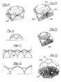
- Figures 13 to 19 illustrate some possible examples of application of structural elements according to the invention, for instance as illustrated in Figure 5 (the tie rods 26 were not shown to simplify the drawings).
- Figure 13 illustrates a covering with hexagonal plan, where six structural elements 24 are provided for, connected to one another in correspondence with the ends of two of their triangular bodies, in a way as to form the bearing structure of the figure, on which a whatever covering can be placed, for instance a covering of flexible and obviously impermeable material.
- the covering can be constituted or supported by another structural element according to the invention, for example of the type as indicated in one of the Figures 9 to 12.
- Figures 16 and 17 illustrate a configuration for covering a shed, in which the structural elements according to the invention, still indicated by 24, are positioned according to four parallel rows and assembled in a position inclined to one another so as to create a dome-like supporting structure as indicated in Figure 16.
- the structural elements 24 can be alternately placed as indicated in Figure 18, still to form the bearing structure of a shed covering.
- Figure 19 illustrates a covering of hemispheric type, consisting of a series of elements derived from the hexagon, in this particular case elements 68 consisting of 24 side polygons, and elements 70 derived from the penthagon, in this particular case polygons formed by twenty sides.
- the connecting elements between the para-hexagons and para-penthagons are constituted by structural elements according to the present invention, as it can be clearly noticed in Figure 19.
- the hemispherical covering can show only structural elements 24 as bearing elements, while para-hexagons and para-penthagons are simple openings provided with non- bearing covering elements, preferably flexible covering elements.
- This Figure clearly shows how the structural elements according to the invention are really derived from a sphere-shaped structure.
- the structural element according to the invention, and consequently the constructions using said structural element can be used in many different ways, according to the desired applications and relevant needs. All these possible different configurations must be considered as coming within the scope of the present invention as defined by the claims.
Landscapes
- Engineering & Computer Science (AREA)
- Architecture (AREA)
- Physics & Mathematics (AREA)
- Electromagnetism (AREA)
- Civil Engineering (AREA)
- Structural Engineering (AREA)
- Glass Compositions (AREA)
- Inorganic Insulating Materials (AREA)
- Thermistors And Varistors (AREA)
- Metal-Oxide And Bipolar Metal-Oxide Semiconductor Integrated Circuits (AREA)
- Joining Of Building Structures In Genera (AREA)
- Transition And Organic Metals Composition Catalysts For Addition Polymerization (AREA)
- Inks, Pencil-Leads, Or Crayons (AREA)
- Buildings Adapted To Withstand Abnormal External Influences (AREA)
- Building Environments (AREA)
- Photometry And Measurement Of Optical Pulse Characteristics (AREA)
- Measurement And Recording Of Electrical Phenomena And Electrical Characteristics Of The Living Body (AREA)
- Laminated Bodies (AREA)
- Bipolar Transistors (AREA)
- Aiming, Guidance, Guns With A Light Source, Armor, Camouflage, And Targets (AREA)
- Adjustable Resistors (AREA)
- Prostheses (AREA)
- Rod-Shaped Construction Members (AREA)
- Semiconductor Lasers (AREA)
Claims (5)
Priority Applications (1)
| Application Number | Priority Date | Filing Date | Title |
|---|---|---|---|
| AT82103098T ATE23204T1 (de) | 1981-04-30 | 1982-04-10 | Strukturelement fuer bauten. |
Applications Claiming Priority (2)
| Application Number | Priority Date | Filing Date | Title |
|---|---|---|---|
| IT21465/81A IT1138282B (it) | 1981-04-30 | 1981-04-30 | Elemento strutturale tridimensionale per costruzioni |
| IT2146581 | 1981-04-30 |
Publications (3)
| Publication Number | Publication Date |
|---|---|
| EP0064176A2 EP0064176A2 (de) | 1982-11-10 |
| EP0064176A3 EP0064176A3 (en) | 1983-04-06 |
| EP0064176B1 true EP0064176B1 (de) | 1986-10-29 |
Family
ID=11182209
Family Applications (1)
| Application Number | Title | Priority Date | Filing Date |
|---|---|---|---|
| EP82103098A Expired EP0064176B1 (de) | 1981-04-30 | 1982-04-10 | Strukturelement für Bauten |
Country Status (12)
| Country | Link |
|---|---|
| US (1) | US4555878A (de) |
| EP (1) | EP0064176B1 (de) |
| JP (1) | JPS57187450A (de) |
| AT (1) | ATE23204T1 (de) |
| AU (1) | AU8265082A (de) |
| BR (1) | BR8202549A (de) |
| DE (1) | DE3274003D1 (de) |
| ES (1) | ES273540Y (de) |
| GR (1) | GR76082B (de) |
| IT (1) | IT1138282B (de) |
| MX (1) | MX154635A (de) |
| ZA (1) | ZA822712B (de) |
Families Citing this family (14)
| Publication number | Priority date | Publication date | Assignee | Title |
|---|---|---|---|---|
| JPS6172148A (ja) * | 1984-09-14 | 1986-04-14 | 有限会社 イタス | 建築構造体 |
| USRE33710E (en) * | 1985-11-06 | 1991-10-08 | World Shelters, Inc. | Portable shelter assemblies |
| US5230196A (en) * | 1990-09-05 | 1993-07-27 | World Shelters, Inc. | Polyhedron building system |
| US6418673B1 (en) * | 1998-09-04 | 2002-07-16 | Steven J. Hultquist | Synetic structural forms and systems comprising same |
| WO2000039415A1 (fr) * | 1998-12-28 | 2000-07-06 | Housing Kosan Co., Ltd. | Structure polyedre et son procede de fabrication |
| AU3264199A (en) * | 1999-03-03 | 2000-10-04 | Coventry University | Module for a space structure and a space structure |
| US7389612B1 (en) * | 2001-08-09 | 2008-06-24 | Fischbeck Richard D | Geodesic structure |
| US7448400B2 (en) * | 2006-07-07 | 2008-11-11 | Jensen Norman L | Modular frame with parabolic top |
| US20110162310A1 (en) * | 2007-07-18 | 2011-07-07 | James Charles Garofalo | Tile And Strut Construction System For Geodesic Dome |
| US20150121772A1 (en) * | 2009-12-23 | 2015-05-07 | Liberty Diversified International, Inc. | System and method for structure design |
| US8959845B2 (en) * | 2009-12-23 | 2015-02-24 | Liberty Diversified International, Inc. | System and method for structure design |
| USD732694S1 (en) * | 2013-03-27 | 2015-06-23 | Cornel Radu | Above-ground shelter |
| CN103765958B (zh) * | 2013-09-29 | 2017-09-29 | 华为终端有限公司 | 搜索网络的方法及装置 |
| US11732496B1 (en) * | 2016-06-30 | 2023-08-22 | DLX Enterprises, LLC | Shelter and hub system |
Family Cites Families (13)
| Publication number | Priority date | Publication date | Assignee | Title |
|---|---|---|---|---|
| FR405398A (fr) * | 1908-07-27 | 1909-12-28 | Jean Jacques Darnal | Procédé de construction de charpentes métalliques pour domes |
| US3026651A (en) * | 1957-08-05 | 1962-03-27 | Kaiser Aluminium Chem Corp | Building construction |
| US3114176A (en) * | 1958-10-14 | 1963-12-17 | Pease Woodwork Company Inc | Wood building construction |
| US3006670A (en) * | 1959-06-02 | 1961-10-31 | Goodyear Aircraft Corp | Frame for supporting domed structures |
| US3018858A (en) * | 1959-08-26 | 1962-01-30 | Gleason Reel Corp | Shelter frame |
| FR1379636A (fr) * | 1963-05-02 | 1964-11-27 | Procédé de construction de dômes stéréométriques | |
| US3201894A (en) * | 1963-06-14 | 1965-08-24 | Ronald D Resch | Geometrical device having articulated relatively movable sections |
| US3392495A (en) * | 1965-01-22 | 1968-07-16 | Geometrics | Spherical structural arrangement |
| US3407558A (en) * | 1966-01-24 | 1968-10-29 | Ronald D. Resch | Self-supporting structural unit having a series of repetitious geometrical modules |
| US3921349A (en) * | 1969-01-08 | 1975-11-25 | Arpad Kolozsvary | Structural component and structures comprising the same |
| IL34092A (en) * | 1970-03-17 | 1974-01-14 | Sircovich O | A new structural element and method of erecting structures therewith |
| SU494501A1 (ru) * | 1973-12-21 | 1975-12-05 | Московский Ордена Трудового Красного Знамени Архитектурный Институт | Сетчатое купольное покрытие |
| US4026078A (en) * | 1976-02-09 | 1977-05-31 | Geometrics | Spherical structural arrangement |
-
1981
- 1981-04-30 IT IT21465/81A patent/IT1138282B/it active
-
1982
- 1982-04-10 EP EP82103098A patent/EP0064176B1/de not_active Expired
- 1982-04-10 DE DE8282103098T patent/DE3274003D1/de not_active Expired
- 1982-04-10 AT AT82103098T patent/ATE23204T1/de not_active IP Right Cessation
- 1982-04-14 US US06/368,176 patent/US4555878A/en not_active Expired - Fee Related
- 1982-04-15 AU AU82650/82A patent/AU8265082A/en not_active Abandoned
- 1982-04-21 ZA ZA822712A patent/ZA822712B/xx unknown
- 1982-04-27 ES ES1982273540U patent/ES273540Y/es not_active Expired
- 1982-04-27 GR GR67989A patent/GR76082B/el unknown
- 1982-04-29 MX MX192498A patent/MX154635A/es unknown
- 1982-04-30 BR BR8202549A patent/BR8202549A/pt unknown
- 1982-04-30 JP JP57071597A patent/JPS57187450A/ja active Pending
Also Published As
| Publication number | Publication date |
|---|---|
| GR76082B (de) | 1984-08-03 |
| US4555878A (en) | 1985-12-03 |
| MX154635A (es) | 1987-11-09 |
| EP0064176A3 (en) | 1983-04-06 |
| EP0064176A2 (de) | 1982-11-10 |
| ES273540Y (es) | 1984-08-01 |
| AU8265082A (en) | 1982-11-04 |
| IT8121465A0 (it) | 1981-04-30 |
| JPS57187450A (en) | 1982-11-18 |
| BR8202549A (pt) | 1983-04-19 |
| ES273540U (es) | 1984-01-16 |
| ZA822712B (en) | 1983-03-30 |
| DE3274003D1 (en) | 1986-12-04 |
| IT1138282B (it) | 1986-09-17 |
| ATE23204T1 (de) | 1986-11-15 |
Similar Documents
| Publication | Publication Date | Title |
|---|---|---|
| US5036641A (en) | Metallic structure | |
| US4555878A (en) | Structural element for constructions | |
| US5331779A (en) | Truss framing system for cluster multi-level housing | |
| US4719726A (en) | Continuous spherical truss construction | |
| US3974600A (en) | Minimum inventory maximum diversity building system | |
| US5235791A (en) | Deck plate | |
| US2682235A (en) | Building construction | |
| US5129203A (en) | Building panel core | |
| US3237362A (en) | Structural unit for supporting loads and resisting stresses | |
| US3953948A (en) | Homohedral construction employing icosahedron | |
| CN1106100A (zh) | 空间桁架拱顶 | |
| US3195274A (en) | Umbrella type frame structures | |
| FI83447C (fi) | Tredimensionellt ramverk. | |
| US3773061A (en) | Modified prestressed membrane structure | |
| JP3045687B2 (ja) | フレーム構造物とその施工方法 | |
| JPS6026900B2 (ja) | 支持構造体 | |
| EP0193662B1 (de) | Bauelemente | |
| RU234551U1 (ru) | Купол двухъярусный | |
| US3132444A (en) | Load-bearing structure | |
| JPS60501417A (ja) | モジュ−ル構造ユニット | |
| CN201176652Y (zh) | 双层索-杆屋盖体系 | |
| JP2613506B2 (ja) | 建築構造物の架構 | |
| JPH03119232A (ja) | 立体トラス | |
| JP3069033B2 (ja) | 立体トラス構造体 | |
| GB2028967A (en) | An improved spring |
Legal Events
| Date | Code | Title | Description |
|---|---|---|---|
| PUAI | Public reference made under article 153(3) epc to a published international application that has entered the european phase |
Free format text: ORIGINAL CODE: 0009012 |
|
| AK | Designated contracting states |
Designated state(s): AT BE CH DE FR GB NL SE |
|
| PUAL | Search report despatched |
Free format text: ORIGINAL CODE: 0009013 |
|
| AK | Designated contracting states |
Designated state(s): AT BE CH DE FR GB LI NL SE |
|
| 17P | Request for examination filed |
Effective date: 19830923 |
|
| RAP1 | Party data changed (applicant data changed or rights of an application transferred) |
Owner name: COTEN S.R.L. |
|
| RIN1 | Information on inventor provided before grant (corrected) |
Inventor name: TRINGALI, MARIO |
|
| GRAA | (expected) grant |
Free format text: ORIGINAL CODE: 0009210 |
|
| AK | Designated contracting states |
Kind code of ref document: B1 Designated state(s): AT BE CH DE FR GB LI NL SE |
|
| REF | Corresponds to: |
Ref document number: 23204 Country of ref document: AT Date of ref document: 19861115 Kind code of ref document: T |
|
| REF | Corresponds to: |
Ref document number: 3274003 Country of ref document: DE Date of ref document: 19861204 |
|
| ET | Fr: translation filed | ||
| PG25 | Lapsed in a contracting state [announced via postgrant information from national office to epo] |
Ref country code: AT Effective date: 19870410 |
|
| PG25 | Lapsed in a contracting state [announced via postgrant information from national office to epo] |
Ref country code: SE Effective date: 19870411 |
|
| PLBE | No opposition filed within time limit |
Free format text: ORIGINAL CODE: 0009261 |
|
| STAA | Information on the status of an ep patent application or granted ep patent |
Free format text: STATUS: NO OPPOSITION FILED WITHIN TIME LIMIT |
|
| 26N | No opposition filed | ||
| BERE | Be: lapsed |
Owner name: COTEN S.R.L. Effective date: 19870430 |
|
| PG25 | Lapsed in a contracting state [announced via postgrant information from national office to epo] |
Ref country code: NL Effective date: 19871101 |
|
| NLV4 | Nl: lapsed or anulled due to non-payment of the annual fee | ||
| PGFP | Annual fee paid to national office [announced via postgrant information from national office to epo] |
Ref country code: FR Payment date: 19890427 Year of fee payment: 8 Ref country code: CH Payment date: 19890427 Year of fee payment: 8 |
|
| PG25 | Lapsed in a contracting state [announced via postgrant information from national office to epo] |
Ref country code: BE Effective date: 19890430 |
|
| PGFP | Annual fee paid to national office [announced via postgrant information from national office to epo] |
Ref country code: DE Payment date: 19890529 Year of fee payment: 8 |
|
| PGFP | Annual fee paid to national office [announced via postgrant information from national office to epo] |
Ref country code: GB Payment date: 19890531 Year of fee payment: 8 |
|
| PG25 | Lapsed in a contracting state [announced via postgrant information from national office to epo] |
Ref country code: GB Effective date: 19900410 |
|
| PG25 | Lapsed in a contracting state [announced via postgrant information from national office to epo] |
Ref country code: LI Effective date: 19900430 Ref country code: CH Effective date: 19900430 |
|
| GBPC | Gb: european patent ceased through non-payment of renewal fee | ||
| PG25 | Lapsed in a contracting state [announced via postgrant information from national office to epo] |
Ref country code: FR Effective date: 19901228 |
|
| REG | Reference to a national code |
Ref country code: CH Ref legal event code: PL |
|
| PG25 | Lapsed in a contracting state [announced via postgrant information from national office to epo] |
Ref country code: DE Effective date: 19910101 |
|
| REG | Reference to a national code |
Ref country code: FR Ref legal event code: ST |
|
| EUG | Se: european patent has lapsed |
Ref document number: 82103098.8 Effective date: 19880906 |