EP0064182A2 - Dispositif de commande de positionnement - Google Patents
Dispositif de commande de positionnement Download PDFInfo
- Publication number
- EP0064182A2 EP0064182A2 EP82103122A EP82103122A EP0064182A2 EP 0064182 A2 EP0064182 A2 EP 0064182A2 EP 82103122 A EP82103122 A EP 82103122A EP 82103122 A EP82103122 A EP 82103122A EP 0064182 A2 EP0064182 A2 EP 0064182A2
- Authority
- EP
- European Patent Office
- Prior art keywords
- signal
- position detector
- control device
- positioning control
- emitted
- Prior art date
- Legal status (The legal status is an assumption and is not a legal conclusion. Google has not performed a legal analysis and makes no representation as to the accuracy of the status listed.)
- Granted
Links
- 230000005856 abnormality Effects 0.000 claims abstract description 23
- 230000002159 abnormal effect Effects 0.000 claims abstract description 10
- 238000001514 detection method Methods 0.000 claims abstract description 6
- 238000000034 method Methods 0.000 description 8
- 238000010586 diagram Methods 0.000 description 2
Images

Classifications
-
- G—PHYSICS
- G05—CONTROLLING; REGULATING
- G05D—SYSTEMS FOR CONTROLLING OR REGULATING NON-ELECTRIC VARIABLES
- G05D3/00—Control of position or direction
- G05D3/12—Control of position or direction using feedback
Definitions
- This invention relates to devices for controlling positioning of moving articles, and more particularly to a positioning control device capable of judging an abnormality in a position detector.
- One method is performed such that an abnormality signal is generated by the position detector itself independently of a position signal, whereby an abnormal condition of the position detector is judged based on the abnormality signal.
- the other method is such that the controller monitors position signals from the position detector at all times, whereby a good or bad positional signal is judged based on the data of movement of an article to be controlled, and emits a signal of judgement.
- An object of the present invention is to provide a p6sitioning control device wherein an abnormality in a position detector can be judged based only on position signals fed from the position detector without using the data of movement of a movable article to be controlled.
- Another object of the present invention is to provide a positioning control device wherein a mistaken position detection of a movable article due to an abnormality in a position detector can be prevented and a highly reliable positioning control can be effected.
- Fig. 1 shows the arrangement of the conventional positioning control device
- Fig. 3 shows the operational time chart thereof.
- designated at 1 is a position detector for detecting a position of a movable article to be controlled
- 2 a controller for feeding a positional control signal 6 in response to positional signals 4 and 5 fed from the position detector 1
- 3 a control circuit for controlling the position of the movable article in response to the position control signal 6.
- the aforesaid position signals 4 and 5 are fed alternately in accordance with the moving direction (forward or rearward, for example) of the movable article.
- Fig. 2 shows the arrangement of another example of the conventional positioning control device and Fig. 4 shows the operational time chart thereof.
- the controller 2 takes in from the control circuit 3 the movement data 9 which shows that the article to be controlled is moving, and, when the article to be controlled is moving, if the position signals 4 and 5 from the position detector 1 show that there is no movement of the article to be controlled even after a predetermined period of time (the region of time T in Fig. 4), then the controller 2 feeds an abnormality judging signal 8.
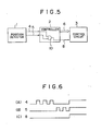
- Fig. 5 shows the arrangement of the positioning control device according to the present invention
- Fig. 6 shows the operational time chart thereof.
- Differences of the positioning control device according to the present invention from the conventional positioning control device reside in firstly, that the position signals 4 and 5 fed from the position detector 1 are adapted to be emitted as logical level "0" signals when the article to be controlled is stopped in movement, secondly, that, when an abnormal condition takes place in the position detector 1, both the position signals 4 and 5 are adapted to be emitted as logical level "0" signals without using the position detection abnormality signal 7 from the position detector 1 as in the prior art, and, thirdly, that, if the position signals 4 and 5 are arranged to emit logical level "0" signals, then an AND gate 10 is adapted to emit a logical "1" signal, the controller 2 emits an abnormality judging signal 8 instantly without using the data of movement 9 of the article to be controlled from the control circuit 3 as in the conventional positioning control device.
- the position signals 4 and 5 are emitted from the position detector 1 in accordance with the moving direction of the movable article, and fed to the AND gate 10 in the controller 2.
- the AND gate 10 is adapted to emit a logical "0" signal, no abnormality judging signal is emitted and the controller 2 feeds to the control circuit 3 a position control signal 6 corresponding to the aforesaid position signal 4 or 5.
- the position signals 4 and 5 fed from the position detector 1 to the AND gate 10 in the controller 2- are adapted to be emitted as logical "1" level signals, an abnormality judging signal 8 is fed from the AND gate 10 to the control circuit 3, and the control circuit 3 stops the positioning control of the movable article.
- abnormality detecting means operable only when a trouble occurs in a detecting element or an electric circuit incorporated in the position detector 1.
- This abnormality detecting means is constructed by the combination of publicly known techniques.
Landscapes
- Physics & Mathematics (AREA)
- General Physics & Mathematics (AREA)
- Engineering & Computer Science (AREA)
- Automation & Control Theory (AREA)
- Control Of Position Or Direction (AREA)
- Safety Devices In Control Systems (AREA)
- Testing And Monitoring For Control Systems (AREA)
- Container, Conveyance, Adherence, Positioning, Of Wafer (AREA)
Applications Claiming Priority (2)
| Application Number | Priority Date | Filing Date | Title |
|---|---|---|---|
| JP67923/81 | 1981-05-06 | ||
| JP56067923A JPS57182809A (en) | 1981-05-06 | 1981-05-06 | Positioning controller |
Publications (3)
| Publication Number | Publication Date |
|---|---|
| EP0064182A2 true EP0064182A2 (fr) | 1982-11-10 |
| EP0064182A3 EP0064182A3 (en) | 1983-11-16 |
| EP0064182B1 EP0064182B1 (fr) | 1988-09-14 |
Family
ID=13358916
Family Applications (1)
| Application Number | Title | Priority Date | Filing Date |
|---|---|---|---|
| EP82103122A Expired EP0064182B1 (fr) | 1981-05-06 | 1982-04-13 | Dispositif de commande de positionnement |
Country Status (6)
| Country | Link |
|---|---|
| US (1) | US4757313A (fr) |
| EP (1) | EP0064182B1 (fr) |
| JP (1) | JPS57182809A (fr) |
| AU (1) | AU561433B2 (fr) |
| CA (1) | CA1176733A (fr) |
| DE (1) | DE3279039D1 (fr) |
Families Citing this family (4)
| Publication number | Priority date | Publication date | Assignee | Title |
|---|---|---|---|---|
| US6232885B1 (en) * | 1998-10-15 | 2001-05-15 | Schlumberger Resource Management Services, Inc. | Electricity meter |
| JP2001228909A (ja) * | 2000-02-16 | 2001-08-24 | Star Micronics Co Ltd | 工作機械及びその制御方法 |
| JP4445510B2 (ja) * | 2007-03-23 | 2010-04-07 | 三菱電機株式会社 | 配線異常検出装置 |
| CN115013401B (zh) * | 2022-05-31 | 2024-06-04 | 三一重能股份有限公司 | 移动销防异动保护系统及方法、移动销装置及风力发电机 |
Family Cites Families (11)
| Publication number | Priority date | Publication date | Assignee | Title |
|---|---|---|---|---|
| US3490010A (en) * | 1966-06-24 | 1970-01-13 | Honeywell Inc | Verification system |
| US3551649A (en) * | 1967-03-23 | 1970-12-29 | Ibm | Position measuring system |
| US3514627A (en) * | 1968-03-20 | 1970-05-26 | Vapor Corp | Proximity switch |
| JPS5197475A (fr) * | 1975-02-24 | 1976-08-27 | ||
| JPS54106776A (en) * | 1978-02-10 | 1979-08-22 | Fanuc Ltd | Positioning device |
| JPS569099A (en) * | 1979-07-03 | 1981-01-29 | Toyo Tokushu Kiki Kk | Abnormality detecting method of automatic press |
| US4321531A (en) * | 1979-09-17 | 1982-03-23 | Sangamo-Weston Inc. | Direction sensitive pulse initiator for a wattmeter |
| NO802936L (no) * | 1979-10-08 | 1981-04-09 | Duraplug Elect Ltd | Elektrisk bryteranordning |
| JPS5680548A (en) * | 1979-12-05 | 1981-07-01 | Aisin Warner Ltd | Throttle opening detector |
| US4401930A (en) * | 1980-12-30 | 1983-08-30 | Toyota Jidosha Kogyo Kabushiki Kaisha | Method of sensing position of movable body and apparatus therefor |
| JPS59112308A (ja) * | 1982-12-20 | 1984-06-28 | Fanuc Ltd | 数値制御装置 |
-
1981
- 1981-05-06 JP JP56067923A patent/JPS57182809A/ja active Pending
-
1982
- 1982-03-31 CA CA000400172A patent/CA1176733A/fr not_active Expired
- 1982-04-13 EP EP82103122A patent/EP0064182B1/fr not_active Expired
- 1982-04-13 DE DE8282103122T patent/DE3279039D1/de not_active Expired
- 1982-05-05 AU AU83406/82A patent/AU561433B2/en not_active Ceased
-
1986
- 1986-07-24 US US06/887,972 patent/US4757313A/en not_active Expired - Lifetime
Also Published As
| Publication number | Publication date |
|---|---|
| EP0064182A3 (en) | 1983-11-16 |
| DE3279039D1 (en) | 1988-10-20 |
| EP0064182B1 (fr) | 1988-09-14 |
| AU8340682A (en) | 1982-11-11 |
| AU561433B2 (en) | 1987-05-07 |
| US4757313A (en) | 1988-07-12 |
| CA1176733A (fr) | 1984-10-23 |
| JPS57182809A (en) | 1982-11-10 |
Similar Documents
| Publication | Publication Date | Title |
|---|---|---|
| US4424458A (en) | Contactless proximity sensor with multilevel response | |
| DE3570385D1 (en) | Electronic surveillance and warning device for a manipulator | |
| GB1529874A (en) | Automatic level control for optical sensors | |
| JPS569099A (en) | Abnormality detecting method of automatic press | |
| US4333719A (en) | Multiple flash adaptor | |
| US4199755A (en) | Optical smoke detector | |
| EP0064182B1 (fr) | Dispositif de commande de positionnement | |
| EP0545828A3 (fr) | Appareil de commande d'alimentation pour dispositif d'affichage | |
| US3825745A (en) | Object detecting system | |
| US4041479A (en) | Output circuit of an ionization smoke sensor | |
| JP2003531426A (ja) | 測定,開ループ制御および閉ループ制御する装置を監視するシステムおよび方法 | |
| US6204575B1 (en) | Method of verifying an extension area sensor controlled, master controller of area sensors, and cover to be used when no slave controller is added | |
| US4879476A (en) | Method and apparatus for transmitting signals | |
| EP0404287A2 (fr) | Méthode de détection de chevauchement de feuille | |
| US5110114A (en) | Method and apparatus for multiple sheet detection | |
| US5297149A (en) | Emergency circuit for, e.g., numerical control unit | |
| DE3466151D1 (en) | Circuit arrangement for the electrically isolated reception of binary electrical signals | |
| JPS534181A (en) | Controlling system | |
| JPS5742244A (en) | Optical transmission system | |
| US4091364A (en) | Combustion detection device | |
| JPH027944A (ja) | 超音波診断装置 | |
| JPS5698089A (en) | Invasion monitor system | |
| JP3299590B2 (ja) | 火災報知設備における端末機器 | |
| EP0839546A3 (fr) | Système de monitoring pendant la calibration | |
| JP2855599B2 (ja) | フォーム送給装置 |
Legal Events
| Date | Code | Title | Description |
|---|---|---|---|
| PUAI | Public reference made under article 153(3) epc to a published international application that has entered the european phase |
Free format text: ORIGINAL CODE: 0009012 |
|
| AK | Designated contracting states |
Designated state(s): DE FR GB |
|
| 17P | Request for examination filed |
Effective date: 19821201 |
|
| PUAL | Search report despatched |
Free format text: ORIGINAL CODE: 0009013 |
|
| AK | Designated contracting states |
Designated state(s): DE FR GB |
|
| RAP1 | Party data changed (applicant data changed or rights of an application transferred) |
Owner name: TOYOTA JIDOSHA KABUSHIKI KAISHA |
|
| GRAA | (expected) grant |
Free format text: ORIGINAL CODE: 0009210 |
|
| AK | Designated contracting states |
Kind code of ref document: B1 Designated state(s): DE FR GB |
|
| REF | Corresponds to: |
Ref document number: 3279039 Country of ref document: DE Date of ref document: 19881020 |
|
| ET | Fr: translation filed | ||
| PLBE | No opposition filed within time limit |
Free format text: ORIGINAL CODE: 0009261 |
|
| STAA | Information on the status of an ep patent application or granted ep patent |
Free format text: STATUS: NO OPPOSITION FILED WITHIN TIME LIMIT |
|
| 26N | No opposition filed | ||
| PGFP | Annual fee paid to national office [announced via postgrant information from national office to epo] |
Ref country code: FR Payment date: 19900415 Year of fee payment: 9 |
|
| PGFP | Annual fee paid to national office [announced via postgrant information from national office to epo] |
Ref country code: DE Payment date: 19900531 Year of fee payment: 9 |
|
| PG25 | Lapsed in a contracting state [announced via postgrant information from national office to epo] |
Ref country code: FR Effective date: 19911230 |
|
| PG25 | Lapsed in a contracting state [announced via postgrant information from national office to epo] |
Ref country code: DE Effective date: 19920201 |
|
| REG | Reference to a national code |
Ref country code: FR Ref legal event code: ST |
|
| PGFP | Annual fee paid to national office [announced via postgrant information from national office to epo] |
Ref country code: GB Payment date: 19920320 Year of fee payment: 11 |
|
| REG | Reference to a national code |
Ref country code: GB Ref legal event code: 746 |
|
| PG25 | Lapsed in a contracting state [announced via postgrant information from national office to epo] |
Ref country code: GB Effective date: 19930413 |
|
| GBPC | Gb: european patent ceased through non-payment of renewal fee |
Effective date: 19930413 |