EP0064185A2 - Appareillage pour la production électrolytique de chlorate alcalin - Google Patents
Appareillage pour la production électrolytique de chlorate alcalin Download PDFInfo
- Publication number
- EP0064185A2 EP0064185A2 EP82103139A EP82103139A EP0064185A2 EP 0064185 A2 EP0064185 A2 EP 0064185A2 EP 82103139 A EP82103139 A EP 82103139A EP 82103139 A EP82103139 A EP 82103139A EP 0064185 A2 EP0064185 A2 EP 0064185A2
- Authority
- EP
- European Patent Office
- Prior art keywords
- section
- solution
- column
- zone
- electrolysis
- Prior art date
- Legal status (The legal status is an assumption and is not a legal conclusion. Google has not performed a legal analysis and makes no representation as to the accuracy of the status listed.)
- Granted
Links
Images


Classifications
-
- C—CHEMISTRY; METALLURGY
- C25—ELECTROLYTIC OR ELECTROPHORETIC PROCESSES; APPARATUS THEREFOR
- C25B—ELECTROLYTIC OR ELECTROPHORETIC PROCESSES FOR THE PRODUCTION OF COMPOUNDS OR NON-METALS; APPARATUS THEREFOR
- C25B15/00—Operating or servicing cells
-
- C—CHEMISTRY; METALLURGY
- C25—ELECTROLYTIC OR ELECTROPHORETIC PROCESSES; APPARATUS THEREFOR
- C25B—ELECTROLYTIC OR ELECTROPHORETIC PROCESSES FOR THE PRODUCTION OF COMPOUNDS OR NON-METALS; APPARATUS THEREFOR
- C25B1/00—Electrolytic production of inorganic compounds or non-metals
- C25B1/01—Products
- C25B1/24—Halogens or compounds thereof
- C25B1/26—Chlorine; Compounds thereof
- C25B1/265—Chlorates
-
- C—CHEMISTRY; METALLURGY
- C25—ELECTROLYTIC OR ELECTROPHORETIC PROCESSES; APPARATUS THEREFOR
- C25B—ELECTROLYTIC OR ELECTROPHORETIC PROCESSES FOR THE PRODUCTION OF COMPOUNDS OR NON-METALS; APPARATUS THEREFOR
- C25B9/00—Cells or assemblies of cells; Constructional parts of cells; Assemblies of constructional parts, e.g. electrode-diaphragm assemblies; Process-related cell features
- C25B9/17—Cells comprising dimensionally-stable non-movable electrodes; Assemblies of constructional parts thereof
Definitions
- the present invention relates to an improved process and apparatus for electrolytically producing alkaline chlorate wherein effective auto-oxidation of hypochlorous acid is attained thereby causing the current efficiency of the electrolysis to be improved.
- the conventional process of electrolytically producing alkaline chlorates from an aqueous solution of alkaline chloride includes two main steps, that is, an electrolysis step and an auto-oxidation step.
- an electrolysis step chlorine ions in the alkaline chloride solution discharge electrons at an anode, whereby hypochlorous acid ions are produced, while hydrogen ions are reduced at a cathode to form hydrogen gases.
- the auto-oxidation step the produced hypochlorous acid is auto-oxidized to form chlorates.
- the above process is accompanied by sub--reactions which lead to a decrease in the current efficiency.
- some of the produced hypochlorous acid is oxidized by the discharge of electrons at the anode to form chlorates with oxygen being generated, while the remaining hypochlorous acid is reduced back to chlorine ions when the oxygen is removed at the cathode.
- apparatuses for electrolytically producing alkaline chlorate have been used, wherein the electrolysis, auto-oxidizing reaction, gas-separation and cooling are effected concurrently within a single unit.
- a single unit is referred to as a "box type" electrolysis vessel.
- box type apparatuses are relatively flat with a large bottom surface area, and because of this a back mix flow reaction is likely to occur causing a low efficiency of the electrolytical production. Further, it is necessary that the electrolysis operation be carried out at a reduced or low temperature in order to protect the apparatus against corrosion. This results in a great amount of electric power being consumed.
- the disclosed apparatus has many disadvantages. Since there are many pipe joints, there is a problem of leakage of the solution from the pipe arrangement.
- the electrolysis vessel and the reaction vessel are arranged spaced apart from each other, which leads to an increased area of floor space being occupied by the apparatus. With such a pipe arrangement, corrosion is likely to occur and, thus, it is necessary that the apparatus be made of expensive anti--corrosive materials, such as titanum, teflon and the like.
- the electrolysis temperature is still low, that is, 60 to 80°C, and, thus, the advantages of a high temperature operation cannot be enjoyed.
- the apparatuses still have to be equipped with a cooling system, which causes the apparatuses to have a complicated structure.
- An object of the present invention is to provide a process and an apparatus for electrolytically producing alkaline chlorates, improved so as to remove the above disadvantages, wherein the auto-oxidation of hypochlorous acid is acceleted effectively with an increased current efficiency at an increased reaction temperature.
- a process of electrolytically producing alkaline chlorate from an aqueous solution of starting materials in at least one cyclic system comprising:
- Hydrochloric acid is added to the solution so that the circulating solution is kept at a pH valve of 5.5 to 6.4 during the electrolysis operation.
- the hydrochloric acid is dosed onto the free surface of the solution at a central portion thereof, said central surface portion facing the top open end of said central hollow section.
- an apparatus for carrying out the above process.
- the apparatus comprises a container of a column type in which there is a lower electrolysis zone having an electrode section and a feed section, an intermediate reaction zone having an elevating section and a descending section forming a piston-flow reactor and an upper gas separation zone,
- the present inventors have sought to achieve an improved process and apparatus for electrolytically producing alkaline chlorate by taking into consideration the following conditions:
- the auto-oxidizing reaction is effected according to the following formula.
- hypochlorous acid ions are produced by the discharge of chlorine ions at the anode, and these acid ions are auto-oxidized to form chlorates. According to the inventor's experiments, the rate of this reaction was confirmed to be about three powers of the entire concentration of the ' hypochlorite and hypochlorous acid, and it was confirmed that the optimum reaction was attained when the mol ratio of hypochlorite to hypochlorous acid is 2:1. Further, from the above experiments, the inventors have found that the optimum auto-oxidation of hypochlorous acid to chlorates can be effected in a piston-flow or plug-flow reactor, not in a back mix flow reactor.
- the optimum reaction is attained at a pH value in the range from 5.5 to 6.4, preferably from 5.8 to 6.1.
- an activation energy for the reaction is 16 n, 18 Kcal/ mol (according to the Arrhenius plotting method), and the reaction rate is 65 times greater than the conventional rate when the operational temperature is increased, for example, from the conventional temperature of 40°C to 100°C.
- the present invention is characterized by the following.
- Another feature of the present invention directed to the dimensions of the apparatus resides in that the ratio of the height of the column to the diameter thereof is not less than 2. If the ratio is less than 2, no effective auto-oxidizing reaction takes place and, thus, the current efficiency is reduced or a back mix reaction takes place.
- the electrolysis zone of the column is designed with the minimum diameter allowed and then the volume of the solution to be held in the column is determined from the required current concentration.
- the height of the column is determined according to the ratio that the height to the diameter is not less than 2.
- the electrolysis according to the present invention takes place under the following conditions:
- the feed solution includes 50 to 300 g/£ of alkaline chloride, 100 to 850 g/l of alkaline chlorate and 3 to 10 9/1 of alkaline chromate.
- the current density is 10 to 30 A/dm 2 and the current concentration is 10 to 30 A/l.
- concentration of alkaline chloride is less than the above critical value, the volume of oxygen generated is increased to such an extent that the anode is damaged by the resultant oxygen.
- concentration of alkaline chloride is higher than the above critical value, alkaline chloride is crystalized and separated from the solution, whereby the electrolysis operation becomes ineffective.
- the concentration of alkaline chlorate the lower limitation is determined by the transformation from alkaline chloride to alkaline chlorate.
- the upper limitation is determined by the critical concentration whereby no crystalized chlorate becomes separated.
- the same apparatus may be used in series, that is, in a cascade arrangement or in a parallel arrangement.
- the concentrations of alkaline chloride and alkaline chlorate are different among the cascaded units and determined by the difference in the positions of the cascades within the apparatus. It should be designed so that the output from the final stage of the apparatus includes alkaline chloride having a concentration as low as possible and alkaline chlorate having a concentration as high as possible.
- the concentration of alkaline chromate when it is lower than the above-mentioned critical level, the cathode loss is increased, with the effect that the formation of rust is likely to occur, that is the cathodic protection is reduced.
- the concentration of alkaline chromate when it is lower than the above-mentioned critical level, the cathode loss is increased, with the effect that the formation of rust is likely to occur, that is the cathodic protection is reduced.
- the concentration of alkaline chromate when it is lower than the above-mentioned critical level, the cathode loss is increased, with the effect that the formation of rust is likely to occur, that is the cathodic protection is reduced.
- the concentration of alkaline chromate when it is lower than the above-mentioned critical level, the cathode loss is increased, with the effect that the formation of rust is likely to occur, that is the cathodic protection is reduced.
- production of oxygen at the anode is increased, which reduces
- the pH value of the reactive solution may be in the range from 5.5 to 6.4, preferably from 5.8 to 6.1.
- the pH value is lower than the above critical value, the chlorine content in the gases generated is increased to such an extent that a dangerous explosive reaction of C1 2 with H 2 may occur. Further, in this case, a load necessary for carrying out a subsequent gas-purifying process is increased.
- the pH value is over the above critical value, the volume of oxygen generated is increased to such an extent that a dangerous explosive reaction of 0 2 with H 2 may occur. This also leads to a reduced current efficiency.
- electrolysis takes place when the solution has not been forceably cooled, but when the solution is at a high temperature of 80 to 115°C.
- the upper limit of 115°C is close to the boilding point of the solution during the operation.
- the temperature is lower than the above-mentioned lower limit, this leads to an increase in the electric power per unit of production. Further, in this case, the amount of the vapour generated is reduced and, thus, the concentration of alkaline chlorate cannot be increased.
- the electrolysis operation can be carried out effectively with a reduced concentration of hypochlorous acid in the range from 0.3 to 1.5 g/l(calculated on the basis of HC10).
- an apparatus for the electrolytical production of alkaline chlorates has a column type container.
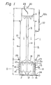
- the column 1 forms successively a lower electrolysis zone A, an intermediate reaction zone B and an upper gas-separation zone C.
- the lower zone A has a cathode vessel 24 forming an electrode cell or section 2 and a feed section 3.
- the electrode section 2 comprises vertical cathode plates 11 equally spaced apart from the neighbouring ones and extending upwardly from the bottom of the cathode vessel 24.
- the electrode section 2 also includes two symmetrical comb-like anodes 13, each having an anode frame 14 and vertical anode plates 13a extending horizontally from the anode frames 14.
- These comb-like anodes 13 are disposed opposite each other in the lower zone A, in such an arrangement that the corresponding anode plates 13a are located between the neighbouring cathode plates 11, so as to be spaced apart from each other at their inner ends and from the neighbouring cathode plates.
- the comb-like anodes 13 are spaced apart from the bottom wall of the column.
- the cathode plates 11 have holes 12 across the width. In this embodiment, the lower edges of the holes are defined by the bottom wall of the column 1.
- These holes in combination, form horizontal through-holes in the electrode section 2, intersecting with the axis of the column 1.
- the anode plates 13a are positioned so as to be above the through-hole. In the above arrangement, the comb-like anodes 13 are electrically insulated from the cathode vessel 24.
- the feed section 3 is defined by the electrode section 2 and the side and bottom walls of the column 1 to form two symmetrical opposite spaces outside of the electrode section 2.
- the two spaces are communicated with each other through the through-hole mentioned above.
- the intermediate zone B has an elevating section 5 extending upwardly from the electrode section along the axis of the column 1 and a descending section 6 surrounding the elevating section 5.
- the elevating section 5 is defined by a draft tube 19 and a shoot 18 connected thereto.
- the shoot 18 is of a reverse funnel form covering the top area of the electrode section 2 and is fixed to the cathode plates 11, which are located opposite each other on the outermost area of the electrode section.
- the descending section 6 is defined by the tube 19 and the circular side wall of the column 1 to form a circumferential space extending vertically around the tube 19, and has an inlet nozzle 21 for introducing the starting material solution and an outlet pipe 22 for discharging the solution out of the column 1, both pipes being located opposite each other at the side wall of the column 1 with the inlet nozzle 21 positioned at a level lower than that of the outlet pipe 22.
- the descending section 6 communicates with the feed section 3 at the top thereof.
- the upper zone C is defined by the side wall and top wall of the column 1 to form a circular area and has an outlet pipe 20 at the top wall of the column 1 for discharging gases produced from the solution in the column 1.
- the circumferential area of the descending section 6 is integrated with the area of the upper zone C and the tube 19 of the elevating section 5 is open to the upper zone area.
- a solution from the inlet nozzle 21 is forced to descend and flow into the feed section 3.
- the introduced solution is fed into the elevating section 5 through the through-hole(12)of the electrode section 2.
- the fed solution is subjected to electrolysis, by which bubbles of gases (mainly hydrogen gas) are produced.
- the resultant solution is forced by the produced gas bubbles to elevate, together with the gases, from the shoot 18 toward the upper zone C through the tube 19.
- the elevating solution overflows from the top open end of the tube 19 into the descending section through the upper zone C.
- the gases are separated from the solution and are discharged out of the column 1 through the gas outlet pipe 20.
- the gas-separated solution descends through the descending section 6 toward the feed section 3.
- the solution is partially discharged out of the column 1 through the outlet pipe 22.
- the outlet pipe 22 is open to the atomosphere, and the upper zone C is also open to the atomosphere.
- the outlet . pipe 22 has a branch pipe 22a which is positioned at a predetermined level close to that of the top open end of the tube 19.
- the free surface S of the solution held in the column is kept at the same level as the above predetermined level.
- the free solution surface S may be either above or below the top open end of the tube 19.
- the solution is ensured to descend through the descending section 6 in a piston-flow manner. Therefore, if specific reactions take place in the solution descending through the descending section 6, the concentrations of the reactants are reduced as the solution descends.
- the solution in the column is forced, by the bubbles of the gases produced, to circulate through the electrode section 2 in the lower electrolysis zone A, the elevating section 5 in the intermediate zone B, the upper gas--separation zone C, the descending section 6 in the intermediate reaction zone B and the feed section 3 in the lower zone A.
- the upper gas-separation zone C has a conduit 23 extending from the top wall of the column into the upper zone C.
- the lower open end of the conduit 23 is designed so as to be positioned above the top open end of the tube 19.
- numeral 15 denotes electric terminals of the anodes
- numeral 16 denotes an electric lead of the cathode in a plate form.
- the cathode lead plate 16 is attached to the bottom wall of the column 1, and is designed so as to be connected to the corresponding lead plate of an adjacent apparatus, if used in a cascade system as indicated in Fig. 6.
- Numeral 26 denotes copper strips electrically connecting segments of the column 1 at a joint flange thereof so that cathodic protection is attained.
- Numeral 25 denotes a cover plate for closing holes of the lower zone of the column, through which holes the two comb-like anodes 13 are inserted in the cathode vessel 24.
- the lower electrolysis zone A formed by the cathode vessel 24, in which the two comb-like anodes 13 are disposed opposite each other
- the intermediate reaction zone B formed by the cylindrical wall and the tube
- the upper gas-separation zone C formed by the cylindrical wall
- the diameter of the upper gas-separation zone C may be reduced, preferably to the minimum level which is allowed.
- the diameter of the electrode zone A is determined from the minimum area of the zone A which must contain a cathode and anode arrangement having the necessary dimensions.
- the height of the column 1 is determined from the required reaction area, that is, the required volume of the solution to be held in the column 1.
- the diameter of the column is preferably 1 to 1.2 m, with a height of 3.5 to 5 m.
- the diameter of the gas--separation zone is preferably 0.7 to 0.8 m.
- the upper limit of the height of the column is about 10 m, from the view-point of resisting the pressure of the electrolysis zone.
- the holes 12 of the cathode plates 11 may be of a rectangular form and are designed to have a dimension of 3 to 20 cm 2 /1000/A, preferably 5 to 15 cm 2 /1000 A. If the dimension of the holes 12 is smaller than the above lower limitation, a smooth circulation of the solution in the column is not ensured.
- the solution is ensured to flow through the descending section 6 at a temperature changing slightly along the flow direction without mixing of the different fluids.
- the solution is ensured to flow through the descending section 6 at a temperature changing slightly along the flow direction without mixing of the different fluids.
- the electrode section 2, the shoot 18 and the draft tube 19 all have.to be sealed from the descending section 6, in order to prevent leakage of the solution, which would lead to the destruction of the piston-flow of the solution and also to prevent leakage of the solution from the descending section into the elevating section, without passing through the electrode section 2, which leakage would cause the concentration of hypochlorous acid to be reduced in the elevating section 5.
- the inner diameter of the draft tube 19 should be determined according to the value of the electrolysis current. However, generally speaking, such diameter may be in the range from 100 to 350 mm.
- the upper open end of the tube 19 may be positioned not more than 100 mm above the free surface S of the solution in the descending section 6 or not more than 300 mm below the free surface S.
- the upper end of the tube 19 is located in the center of the upper gas-separation zone C, so that the solution is forced to flow radially out of the upper open end of the tube 19, and, thus, is distributed uniformly over the top circumferential area of the descending section. This enhances a so-called "volume efficiency" of the auto-oxidation of hypochlorous acid, that is, the efficiency of the auto--oxidation per unit volume of the solution is increased.
- the inventors have investigated the relationship between the diameter of the apparatus and the volume efficiency, comparing the conventional box type apparatus with the column type apparatus of the present invention.
- Fig. 3 As is apparent from Fig. 3, the volume efficiency is reduced as the diameter of the apparatus increases, and in an apparatus having a diameter over 2 m, only half the volume of the solution held in the apparatus contributes to the auto-oxidation. This implies that a back mix flow reaction is likely to take place as the diameter of the apparatus increases.
- the diameter may be in the range from 0.5 to 1.3 m in order to contain the necessary volume of the solution in the apparatus.
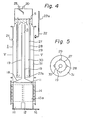
- the diameter should be 0.5 to 1.0 m. If a large scale apparatus in the same arrangement as shown in Fig. 1 having a diameter over 1.3 m is employed, it is preferable to modify the apparatus, so as to elongate the length of the passage, through which the solution is forced to descend while the auto-oxidation is taking place, with the cross-sectional area of the passage being reduced. Such modification, for example, is shown in Fig. 4 and Fig. 5.
- the modified apparatus has a cylindrical vessel 27 enclosing the draft tube 19 and being coaxial therewith, thereby to form an inner local passage 30.
- the cylindrical vessel 27 has a lower closed end and an upper open end, and has four openings 27a, at the lower end, equiangularly spaced apart.
- the upper end of the vessel 27 is positioned above the upper end of the tube 19.
- partitions 29, of a vertical extension having a semi-circular cross section are mounted onto the outside of the vessel 27, thereby to form intermediate local passages 28.
- Lower ends of the partitions 29 are integrated with the lower end of the vessel 27, in such an arrangement that the inner local passage 30 communicates with the respective intermediate passage 28 through the openings 27a.
- Upper ends of the partitions 29 are positioned at the same level as that of the upper end of the draft tube 19.
- An outer local passage 31 is defined by the side wall of the column 1, the partitions 29, the vessel 27, the draft tube 19 and the shoot 18.
- the height of the vessel 27 is designed so that the solution circutating in the column 1 is prevented from entering the outer local passage 31.
- the solution is forced to flow from the upper end of the tube 19 into the inner local passage 30 and descend through the passage 30 in a piston-flow manner and then flow into the intermediate local passages 28 through the openings 27a.
- the solution is forced to elevate through the intermediate local passage 28 and then flow from the upper end of partitions 29 into the outer local passage 31.
- the solution then descends through the outer local passage 31 in a piston-flow manner toward the feed section 3.
- the cylindrical vessel 27 may be disposed in the reaction zone B with a pipe therein, so that the inner local passage 30 is formed between the draft tube 19 and the pipe and an intermediate local passage 28 is formed between the vessel and the pipe.
- the resultant intermediate local passage 28 has a circumferential sectional view.
- the vessel may be partially with the pipe, in a cross-sectional view, so that integrated separate intermediate local passages, corresponding to those shown in Fig. 5, are formed.
- the inventors carried out a test in which the apparatus of the present invention, employed in example 1 described hereinafter, was operated under the same conditions as those applied in a comventional box type apparatus.
- the conditions are: current of 9000A; current density at anode of 18.8A/dm ; temperature of 55°C; NaCl of 100 g/t; NaC10 3 of 480 g/k; Na 2 CrO 4 of 3.7 g/l; and pH of 6.7.
- the volume efficiency was determined by using a ratio of the obtained amount of the auto-oxidized product from hypochlorous acid to the theoretical value of thereof.
- the resultant volume efficiency was 86%.
- the corresponding volume efficiency of the conventional box type apparatus was 55%.
- aqueous hydrochloric acid is preferably dosed onto the free surface of the solution from the dosing conduit 23.
- the solution is kept at a pH value in the range from 5.5 to 6.4, preferably 5.8 to 6.1.
- hydrochloric acid In order to attain effective auto-oxidation of hypo- cholorous acid, it is desirable to dose hydrochloric acid into a local zone of the solution where the solution is stirred intensively by the bubbles of hydrogen gas or the like, which bubbles are then separated and discharged out of the column. This local stirred zone of the solution is just above the upper open end of the draft tube. If hydrochloric acid is dosed into another local portion of the solution where the solution flows slowly, for example, in a portion of the solution in the descending section, the solution becomes locally acidic at that portion. This causes the dosed hydrochloric acid to dissolve to form explosive chlorine dioxide gas. Particularly, where the pH value is reduced to about 6.0 at a high temperature of not less than 80°C, it is very necessary to dose hydrochloric acid into the portion of the solution where the solution is stirred or mixed the most intensively.
- the apparatus is provided with means for thermal insulation so that the increased temperature of the solution in the column can be kept in the range from 80 to 115°C, preferably 90 to 110°C with a minimum loss of thermal energy generated by the electrolysis.
- This is an effective utilization of the thermal energy which, otherwise, becomes a loss of electric power during electrolysis.
- the electrolysis operation can be carried out under a reduced voltage applied to the electrodes.
- the present invention features no provision of means for cooling the lower electrolysis zone and, in turn, electrolysis takes place with the solution at a high temperature.
- Such a high temperature electrolysis operation accelates the auto-oxidation reaction of hypochlorite thereby to improve the current efficiency.
- an amount of the vapour carried by the produced hydrogen gas is increased and, thus, the concentration of alkaline chlorate is increased.
- This leads to a reduction in the amount of water to be removed in the vapour phase from the output solution in the subsequent vapouring process whereby the produced chlorate is separated from the electrolyte.
- a problem may occur, particularly in a cascade system of a pluratity of the column type apparatus as shown in Fig. 6, wherein condensation of the solution may be excessively accelerated so that alkaline chloride and/or alkaline chlorate is crystalized and separated from the solution.
- the cathode vessel 24 and the cathode plates 11 forming the lower electrolysis zone A are made of iron or an iron alloy. However, these iron members are prevented from being corroded owing to the electrolysis current.
- the covering plates 25 to close the openings through which the comb-like anodes 13 are inserted are made of an iron material. It is advantageous to connect these electrically to the cathode vessel 24 by copper strips 26, thereby to effect cathodic protection. In this case, it is preferable to employ copper strips having a thickness of 3 to 5 mm and a width of 50 to 100 mm. It is preferred that at least four copper strips be used and located so as to be equally spaced apart from the neighbouring ones along the circumference of a flange joining the column segments.
- the column type apparatus of the present invention is of a simple construction or arrangement and includes constructive members having relatively small areas to be cathodic--protected, where the solution contacts the members.
- the current density in the above mentioned range is enough to attain effective cathodic protection.
- the concentration of hypochorous acid is high, the cathodic reduction reaction tends to occur at the surface of the member to be cathodic-protected, with the result that the electric potential becomes adequately high or noble to promote corrosion of the surface of the member.
- the concentration of hypochlorous acid is extremely low and the concentration of chromate is kept at a high level of 5 to 10 g/9.
- the surface of the member to be cathodic-protected is coated with a thick layer formed thereon, which layer prevents the reduction of hypochlorous acid from occurring, thereby attaining an effective protection of the iron members empolyed in the apparatus.
- the cathode vessel 24 of soft iron was provided therein with eleven sheets of cathode plates 11 having rectangular holes, at the central bottom portion, each plate 11 having a height of 15 cm and a width of 8 cm.
- the cathode plates 11 were welded to the bottom surface of the vessel 24.
- the comb-like anodes 13 are combined with the cathode plates 11 in such an arrangement that the two comb-like anodes 13 were located oppositely with each anode plate 13a positioned between the neighbouring cathode plates 11 with a gap of 0.25 cm between each anode plate and the adjacent cathode plate.
- a cylinder la of soft iron having a height of 1.54 m and a diameter of 0.5 m, was connected at a circumferential joint flange, to form the intermediate reaction zone B.
- the cathode vessel 24 and the cylinder la were electrically connected by four copper strips 26 located around the cylinder la at the joint flange.
- the copper strips 26 have a width of 10 cm and a thickness of 5 mm.
- the draft tube 19 of titanum having a height of 2.2 m, a thickness of 0.5 mm and a diameter of 0.1 m, was disposed coaxially with the cylinder la and was connected to the shoot 18.
- the outlet pipe 22, for discharging the output solution from the column, and the draft tube 19 were designed so that the electrolyte solution during the operation had a free surface S, in the space defined by the column wall and draft tube, positioned 0.3 m below the top wall of the column, and the upper open end of the draft tube was positioned 0.2 m below the level of the liquid free surface S.
- the entire arrangement was insulated thermally so as to prevent the temperature of the liquid from being lowered, due to the radiation of thermal energy.
- the above apparatus was operated with: a current of 12000A (anode current density of 25 A/dm 2 , current concentration of 19.6 A/l); with a starting chloride solution or feed brine, having a composition of 290 g/l of NaCl, 94 g/ ⁇ of NaClO 3 , 7.6 g/l of Na 2 CrO 4 and water, fed at a feeding rate of 23.2 kg; a dosing solution containing 140 g/l of hydrochloric acid fed at a feeding rate of 1 kg/h; and water fed at a feeding rate of 3.5 kg/h, while the output solution having a composition of 97 g/l of NaCl, 639 g/l of NaClO 3 and 8.9 g/L of Na 2 CrO 4 and a pH value of 5.9 was removed at a discharging rate of 20.7 kg/h.
- the amount of NaClO 3 produced by the electrolysis operation was 7.5 kg/h. The operation was continued for about 10 months at
- the average current efficiency was 95.6%
- the average electrolysis voltage was 2.82 V
- the average electric power for electrolysis per unit of production was 4450 KWH(D. C.)/ton.
- the operation was carried out with the electrolyte including hypochlorous acid having a reduced concentration of 0.42 g/l (calculated on the basis of HC10).
- the inventors carried out the below-mentioned experiments in order to investigate preferable and critical conditions regarding the temperature, the pH value and cathodic protection.
- the apparatus had the same arrangement and dimensions as that of the above example, except for the following.
- the titanum draft tube 19 was provided with a jacket, having a diameter of 15 cm, in which cooling and heating means were provided, so that the temperature of the liquid in the intermediate reaction zone was able to be adjusted.
- the above mentioned apparatus was operated with a current of 12000A to produce an output solution, having a composition of 105 g/l of NaCl, 480 g/l of NaClO 3 and 7.5 g/l of Na 2 CrO 4 at a pH value of 6.0 under various temperature conditions.
- the content of C1 2 in the generated gases is increased as the temperature becomes higher.
- the Cl content reached 1.5%.
- such chlorine was captured in a subsequent gas--purification process and was recovered in the form of NaClO 3 to be returned to the electrolysis system.
- the recovered chlorine gas was taken into consideration as an effective material, when calculating the current efficiency, not a lost material.
- the concentration of hypochlorous acid was changed according to the current density, but in the range from 0.31 to 0.48 g/f (calculated on the basis of HC10).
- the anti-corrosion effect was enhanced as the concentration of Na 2 CrO 4 and the anode current density were increased. From these data, it was confirmed that effective anti-corrosion can be attained, provided that the apparatus is operated at a concentration of Na 2 CrO 4 not less than 4.7 g/l and an anode density not less than 10 A/dm .
- the corrosion of Fe greatly relies on the concentration of hypochlorous acid.
- the apparatus can be designed so as to be operated at a very high temperature and a reduced pH value, the concentration of hypochlorous acid is considerably reduced with the result that effective anti-corrosion is definitely attained, even if the apparatus is made mainly of soft iron.
Landscapes
- Chemical & Material Sciences (AREA)
- Engineering & Computer Science (AREA)
- Chemical Kinetics & Catalysis (AREA)
- Electrochemistry (AREA)
- Materials Engineering (AREA)
- Metallurgy (AREA)
- Organic Chemistry (AREA)
- Inorganic Chemistry (AREA)
- Electrolytic Production Of Non-Metals, Compounds, Apparatuses Therefor (AREA)
Applications Claiming Priority (2)
| Application Number | Priority Date | Filing Date | Title |
|---|---|---|---|
| JP56057123A JPS5928635B2 (ja) | 1981-04-17 | 1981-04-17 | 塩素酸アルカリ用塔式電解装置及び塩素酸アルカリの電解製造方法 |
| JP57123/81 | 1981-04-17 |
Publications (4)
| Publication Number | Publication Date |
|---|---|
| EP0064185A2 true EP0064185A2 (fr) | 1982-11-10 |
| EP0064185A3 EP0064185A3 (en) | 1983-02-16 |
| EP0064185B1 EP0064185B1 (fr) | 1986-08-27 |
| EP0064185B2 EP0064185B2 (fr) | 1990-03-07 |
Family
ID=13046773
Family Applications (1)
| Application Number | Title | Priority Date | Filing Date |
|---|---|---|---|
| EP82103139A Expired EP0064185B2 (fr) | 1981-04-17 | 1982-04-14 | Appareillage pour la production électrolytique de chlorate alcalin |
Country Status (5)
| Country | Link |
|---|---|
| US (1) | US4469576A (fr) |
| EP (1) | EP0064185B2 (fr) |
| JP (1) | JPS5928635B2 (fr) |
| CA (1) | CA1198076A (fr) |
| DE (1) | DE3272829D1 (fr) |
Cited By (3)
| Publication number | Priority date | Publication date | Assignee | Title |
|---|---|---|---|---|
| FR2607723A1 (fr) * | 1986-12-04 | 1988-06-10 | Eka Nobel Ab | Procede pour la production de chlorate de metal alcalin notamment pour l'industrie de la cellulose par electrolyse comportant une purification de l'hydrogene |
| BE1005732A3 (fr) * | 1992-04-17 | 1994-01-11 | Solvay | Procede d'epuration d'une solution aqueuse en ions hypochloreux et procede de fabrication d'une solution aqueuse de chlorate de sodium. |
| EP0615003A1 (fr) * | 1993-03-11 | 1994-09-14 | De Nora Permelec S.P.A. | Dispositif de préparation et de stockage d'hypochlorite de métal alcalin |
Families Citing this family (7)
| Publication number | Priority date | Publication date | Assignee | Title |
|---|---|---|---|---|
| US5064514A (en) * | 1990-03-30 | 1991-11-12 | Olin Corporation | Apparatus for the production of chloric acid |
| US5108560A (en) * | 1990-03-30 | 1992-04-28 | Olin Corporation | Electrochemical process for production of chloric acid from hypochlorous acid |
| US6805787B2 (en) | 2001-09-07 | 2004-10-19 | Severn Trent Services-Water Purification Solutions, Inc. | Method and system for generating hypochlorite |
| US7946508B2 (en) * | 2004-03-30 | 2011-05-24 | Ultrasound Brewery | Method and apparatus for separating a solution |
| GB0618789D0 (en) * | 2006-09-23 | 2006-11-01 | Sev Trent Services Ltd | Electrolytic cell |
| CN108265313A (zh) * | 2018-03-27 | 2018-07-10 | 浙江长控电气科技有限公司 | 电解装置及用其电解稀食盐水制取酸性和碱性溶液的方法 |
| CN109234763B (zh) * | 2018-11-20 | 2023-11-10 | 青岛双瑞海洋环境工程股份有限公司 | 电解食盐水制取次氯酸钠装置性能全自动试验系统 |
Family Cites Families (11)
| Publication number | Priority date | Publication date | Assignee | Title |
|---|---|---|---|---|
| FR956421A (fr) * | 1950-02-01 | |||
| US3234117A (en) * | 1962-10-26 | 1966-02-08 | Beckman Instruments Inc | Galvanic cell for analyzing gas |
| DE1567621B2 (de) * | 1965-07-23 | 1972-06-29 | Krebs & Co AG, Zürich (Schweiz) | Verfahren und vorrichtung zur herstellung von alkalichlorat durch elektrolyse waessriger alkalichloridloesungen |
| GB1200272A (en) * | 1967-11-13 | 1970-07-29 | Nautchno Izsledovatelski Inst | Improvements in or relating to electrodes for electrolysis |
| DE2039590A1 (de) * | 1970-08-08 | 1972-02-10 | Basf Ag | Bipolare Elektrode |
| US3756933A (en) * | 1971-08-25 | 1973-09-04 | B Greenberg | Method of purifying sewage efluent and apparatus therefor |
| US3732153A (en) * | 1971-10-05 | 1973-05-08 | Hooker Chemical Corp | Electrochemical apparatus and process for the manufacture of halates |
| IT1003156B (it) * | 1973-10-30 | 1976-06-10 | Oronzio De Nora Impianti | Elettrolizzatore per la produzione di composti ossigenati del cloro da soluzioni di cloruri alcalini |
| IT1031897B (it) * | 1975-02-20 | 1979-05-10 | Oronzio De Nora Impianti | Procedimento e apparecchiatura per la produzione di alogenati alcalini |
| US4332648A (en) * | 1979-12-17 | 1982-06-01 | Hooker Chemicals & Plastics Corp. | Electrolytic apparatus for the manufacture of alkali metal halate |
| US4332659A (en) * | 1979-12-17 | 1982-06-01 | Hooker Chemicals & Plastics Corp. | Electrolytic apparatus for the manufacture of alkali metal halate |
-
1981
- 1981-04-17 JP JP56057123A patent/JPS5928635B2/ja not_active Expired
-
1982
- 1982-04-14 EP EP82103139A patent/EP0064185B2/fr not_active Expired
- 1982-04-14 DE DE8282103139T patent/DE3272829D1/de not_active Expired
- 1982-04-14 US US06/368,122 patent/US4469576A/en not_active Expired - Lifetime
- 1982-04-16 CA CA000401114A patent/CA1198076A/fr not_active Expired
Cited By (3)
| Publication number | Priority date | Publication date | Assignee | Title |
|---|---|---|---|---|
| FR2607723A1 (fr) * | 1986-12-04 | 1988-06-10 | Eka Nobel Ab | Procede pour la production de chlorate de metal alcalin notamment pour l'industrie de la cellulose par electrolyse comportant une purification de l'hydrogene |
| BE1005732A3 (fr) * | 1992-04-17 | 1994-01-11 | Solvay | Procede d'epuration d'une solution aqueuse en ions hypochloreux et procede de fabrication d'une solution aqueuse de chlorate de sodium. |
| EP0615003A1 (fr) * | 1993-03-11 | 1994-09-14 | De Nora Permelec S.P.A. | Dispositif de préparation et de stockage d'hypochlorite de métal alcalin |
Also Published As
| Publication number | Publication date |
|---|---|
| JPS57171675A (en) | 1982-10-22 |
| EP0064185B2 (fr) | 1990-03-07 |
| EP0064185B1 (fr) | 1986-08-27 |
| CA1198076A (fr) | 1985-12-17 |
| US4469576A (en) | 1984-09-04 |
| JPS5928635B2 (ja) | 1984-07-14 |
| DE3272829D1 (en) | 1986-10-02 |
| EP0064185A3 (en) | 1983-02-16 |
Similar Documents
| Publication | Publication Date | Title |
|---|---|---|
| US4495048A (en) | Apparatus for electrolysis of saline water | |
| US4194953A (en) | Process for producing chlorate and chlorate cell construction | |
| FI68266C (fi) | Apparat foer tillverkning av natriumhypoklorit | |
| JP7123072B2 (ja) | 自己洗浄同心管電気化学セルの新しい流れ特徴部 | |
| US4469576A (en) | Apparatus for electrolytical production of alkaline chlorate | |
| US4048047A (en) | Electrochemical cell with bipolar electrodes | |
| US3766044A (en) | Electrolytic cell system including upper and lower reacting chambers | |
| US4372827A (en) | Novel horizontal diaphragmless electrolyzer | |
| US4059495A (en) | Method of electrolyte feeding and recirculation in an electrolysis cell | |
| US3930980A (en) | Electrolysis cell | |
| US4139449A (en) | Electrolytic cell for producing alkali metal hypochlorites | |
| FI65282B (fi) | Elektrokemisk anordning och foerfarande foer tillverkning av halater | |
| CA1162879A (fr) | Dispositif electrolytique pour la fabrication d'halate de metal alcalin | |
| US4824534A (en) | Process for electrically separating the electrolyte-bearing mains from the electrolyte spaces of an electrochemical cell pile | |
| CA1073846A (fr) | Methode et appareil d'electrolyse | |
| US4326941A (en) | Electrolytic cell | |
| US4161438A (en) | Electrolysis cell | |
| US3475313A (en) | Electrolytic cell for chlorate manufacture | |
| US3298946A (en) | Electrolytic bipolar alkali chlorate cell | |
| US3948748A (en) | Apparatus for the production of alkali metal chlorates | |
| US4332659A (en) | Electrolytic apparatus for the manufacture of alkali metal halate | |
| CA1109019A (fr) | Construction d'une cellule a chlorate | |
| EP0538474B1 (fr) | Cuve a electrolyse pour la production d'hypochlorite | |
| JPH0520517B2 (fr) | ||
| EP0007951B1 (fr) | Cellule electrochimique et procede |
Legal Events
| Date | Code | Title | Description |
|---|---|---|---|
| PUAI | Public reference made under article 153(3) epc to a published international application that has entered the european phase |
Free format text: ORIGINAL CODE: 0009012 |
|
| 17P | Request for examination filed |
Effective date: 19820511 |
|
| AK | Designated contracting states |
Designated state(s): DE FR GB SE |
|
| PUAL | Search report despatched |
Free format text: ORIGINAL CODE: 0009013 |
|
| AK | Designated contracting states |
Designated state(s): DE FR GB SE |
|
| GRAA | (expected) grant |
Free format text: ORIGINAL CODE: 0009210 |
|
| AK | Designated contracting states |
Kind code of ref document: B1 Designated state(s): DE FR GB SE |
|
| REF | Corresponds to: |
Ref document number: 3272829 Country of ref document: DE Date of ref document: 19861002 |
|
| ET | Fr: translation filed | ||
| PLBI | Opposition filed |
Free format text: ORIGINAL CODE: 0009260 |
|
| 26 | Opposition filed |
Opponent name: EKA NOBEL AKTIEBOLAG Effective date: 19870514 |
|
| PUAH | Patent maintained in amended form |
Free format text: ORIGINAL CODE: 0009272 |
|
| STAA | Information on the status of an ep patent application or granted ep patent |
Free format text: STATUS: PATENT MAINTAINED AS AMENDED |
|
| 27A | Patent maintained in amended form |
Effective date: 19900307 |
|
| AK | Designated contracting states |
Kind code of ref document: B2 Designated state(s): DE FR GB SE |
|
| ET3 | Fr: translation filed ** decision concerning opposition | ||
| EAL | Se: european patent in force in sweden |
Ref document number: 82103139.0 |
|
| PGFP | Annual fee paid to national office [announced via postgrant information from national office to epo] |
Ref country code: FR Payment date: 19960319 Year of fee payment: 15 |
|
| PGFP | Annual fee paid to national office [announced via postgrant information from national office to epo] |
Ref country code: GB Payment date: 19960409 Year of fee payment: 15 |
|
| PGFP | Annual fee paid to national office [announced via postgrant information from national office to epo] |
Ref country code: SE Payment date: 19960429 Year of fee payment: 15 |
|
| PGFP | Annual fee paid to national office [announced via postgrant information from national office to epo] |
Ref country code: DE Payment date: 19960626 Year of fee payment: 15 |
|
| PG25 | Lapsed in a contracting state [announced via postgrant information from national office to epo] |
Ref country code: GB Effective date: 19970414 |
|
| PG25 | Lapsed in a contracting state [announced via postgrant information from national office to epo] |
Ref country code: SE Effective date: 19970415 |
|
| GBPC | Gb: european patent ceased through non-payment of renewal fee |
Effective date: 19970414 |
|
| PG25 | Lapsed in a contracting state [announced via postgrant information from national office to epo] |
Ref country code: FR Free format text: LAPSE BECAUSE OF NON-PAYMENT OF DUE FEES Effective date: 19971231 |
|
| PG25 | Lapsed in a contracting state [announced via postgrant information from national office to epo] |
Ref country code: DE Free format text: LAPSE BECAUSE OF NON-PAYMENT OF DUE FEES Effective date: 19980101 |
|
| EUG | Se: european patent has lapsed |
Ref document number: 82103139.0 |
|
| REG | Reference to a national code |
Ref country code: FR Ref legal event code: ST |