EP0064197A2 - Procédé d'usinage d'une surface cylindrique - Google Patents
Procédé d'usinage d'une surface cylindrique Download PDFInfo
- Publication number
- EP0064197A2 EP0064197A2 EP82103225A EP82103225A EP0064197A2 EP 0064197 A2 EP0064197 A2 EP 0064197A2 EP 82103225 A EP82103225 A EP 82103225A EP 82103225 A EP82103225 A EP 82103225A EP 0064197 A2 EP0064197 A2 EP 0064197A2
- Authority
- EP
- European Patent Office
- Prior art keywords
- cylindrical
- cylindrical surface
- cylindrical portion
- punch
- processing
- Prior art date
- Legal status (The legal status is an assumption and is not a legal conclusion. Google has not performed a legal analysis and makes no representation as to the accuracy of the status listed.)
- Granted
Links
Images


Classifications
-
- B—PERFORMING OPERATIONS; TRANSPORTING
- B21—MECHANICAL METAL-WORKING WITHOUT ESSENTIALLY REMOVING MATERIAL; PUNCHING METAL
- B21J—FORGING; HAMMERING; PRESSING METAL; RIVETING; FORGE FURNACES
- B21J5/00—Methods for forging, hammering, or pressing; Special equipment or accessories therefor
- B21J5/06—Methods for forging, hammering, or pressing; Special equipment or accessories therefor for performing particular operations
- B21J5/12—Forming profiles on internal or external surfaces
-
- B—PERFORMING OPERATIONS; TRANSPORTING
- B21—MECHANICAL METAL-WORKING WITHOUT ESSENTIALLY REMOVING MATERIAL; PUNCHING METAL
- B21C—MANUFACTURE OF METAL SHEETS, WIRE, RODS, TUBES, PROFILES OR LIKE SEMI-MANUFACTURED PRODUCTS OTHERWISE THAN BY ROLLING; AUXILIARY OPERATIONS USED IN CONNECTION WITH METAL-WORKING WITHOUT ESSENTIALLY REMOVING MATERIAL
- B21C37/00—Manufacture of metal sheets, rods, wire, tubes, profiles or like semi-manufactured products, not otherwise provided for; Manufacture of tubes of special shape
- B21C37/06—Manufacture of metal sheets, rods, wire, tubes, profiles or like semi-manufactured products, not otherwise provided for; Manufacture of tubes of special shape of tubes or metal hoses; Combined procedures for making tubes, e.g. for making multi-wall tubes
- B21C37/15—Making tubes of special shape; Making tube fittings
- B21C37/152—Making rifle or gun barrels
- B21C37/153—Making tubes with inner or outer guides
-
- B—PERFORMING OPERATIONS; TRANSPORTING
- B21—MECHANICAL METAL-WORKING WITHOUT ESSENTIALLY REMOVING MATERIAL; PUNCHING METAL
- B21C—MANUFACTURE OF METAL SHEETS, WIRE, RODS, TUBES, PROFILES OR LIKE SEMI-MANUFACTURED PRODUCTS OTHERWISE THAN BY ROLLING; AUXILIARY OPERATIONS USED IN CONNECTION WITH METAL-WORKING WITHOUT ESSENTIALLY REMOVING MATERIAL
- B21C37/00—Manufacture of metal sheets, rods, wire, tubes, profiles or like semi-manufactured products, not otherwise provided for; Manufacture of tubes of special shape
- B21C37/06—Manufacture of metal sheets, rods, wire, tubes, profiles or like semi-manufactured products, not otherwise provided for; Manufacture of tubes of special shape of tubes or metal hoses; Combined procedures for making tubes, e.g. for making multi-wall tubes
- B21C37/15—Making tubes of special shape; Making tube fittings
- B21C37/20—Making helical or similar guides in or on tubes without removing material, e.g. by drawing same over mandrels, by pushing same through dies ; Making tubes with angled walls, ribbed tubes or tubes with decorated walls
- B21C37/207—Making helical or similar guides in or on tubes without removing material, e.g. by drawing same over mandrels, by pushing same through dies ; Making tubes with angled walls, ribbed tubes or tubes with decorated walls with helical guides
-
- B—PERFORMING OPERATIONS; TRANSPORTING
- B21—MECHANICAL METAL-WORKING WITHOUT ESSENTIALLY REMOVING MATERIAL; PUNCHING METAL
- B21K—MAKING FORGED OR PRESSED METAL PRODUCTS, e.g. HORSE-SHOES, RIVETS, BOLTS OR WHEELS
- B21K1/00—Making machine elements
- B21K1/28—Making machine elements wheels; discs
- B21K1/30—Making machine elements wheels; discs with gear-teeth
-
- B—PERFORMING OPERATIONS; TRANSPORTING
- B21—MECHANICAL METAL-WORKING WITHOUT ESSENTIALLY REMOVING MATERIAL; PUNCHING METAL
- B21K—MAKING FORGED OR PRESSED METAL PRODUCTS, e.g. HORSE-SHOES, RIVETS, BOLTS OR WHEELS
- B21K1/00—Making machine elements
- B21K1/28—Making machine elements wheels; discs
- B21K1/30—Making machine elements wheels; discs with gear-teeth
- B21K1/305—Making machine elements wheels; discs with gear-teeth helical
Definitions
- the present invention relates to a method of processing a cylindrical surface and, more particularly, to a method for mechanically processing the inner or outer cylindrical surface of a cylindrical part in which a punch in the cylindrical part and a die fitted to the outside of the cylindrical part are moved relatively to each other in the axial direction of the cylindrical part to impart a tension to the processed surface to effect a plastic deformation, thereby to form grooves or teeth in the processed surface.
- cutting work has been adopted as a major processing method for producing cylindrical parts having grooves or teeth in the inner or outer peripheral surface threreof such as parts having a helical involute spline in the cylindrical surface, e.g. the outer part of one-way clutch of automotive starter, parts for automotive transmission and so forth.
- the cutting work suffers various disadvantage such as uneconomically high cost of the tool, short life of the tool requiring frequent grinding and impractically long processing time attributable to the inferior working efficiency.
- the processing of cylindrical surface by cutting work raises the overall cost of the products. This is quite disadvantageous from the view point of mass-production of parst, particularly automotive parts.
- the plastic deformation of the blank material is made solely by the compression applied to the blank, so that the blank can hardly be deformed to require a large force for driving the punch.
- the blank material is pressed by a force greater than the resistance to the compression, a seizure is liable to occur between the punch and the blank or between the die and the blank.
- the grooves or teeth cannot be formed at sufficiently high precision.
- this known method relying upon compression deformation is to forcibly deform the blank while keeping the latter under a condition resisting to the deformation.
- this method could process, when applied to the production of a part having a helical involute spline in its inner peripheral surface, only a small helical angle of about 18° or less. Namely, helical angle in excess of 18° could not be processed by this known method because of a seizure of the punch.
- an object of the invention is to provide a method of processing a cylindrical surface in which a tension is applied to the blank material during the formation to permit a plastic work with a force smaller than the deformation resistance of the material, to make it possible to form grooves or teeth at high dimentional precision with a comparatively small force of driving of the punch without seizure, thereby to overcome the above- described problems of the prior art.
- Another object of the invention is to provide a method of processing a cylindrical surface suitable for processing the inner or outer cylindrical surface of a blank material and capable of forming grooves or teeth in the inner or outer cylindrical surface of the blank material at a high dimensional precision by plactic deformation with a comparatively small driving force of the punch while eliminating the undesirable seizure of the punch or die.
- Fig. 1 is an illustration of a conventional processing method for forming a helical involute spline in the inner cylindrical surface of a cylindrical part by a cold plastic work.
- a cylindrical blank 1 is supported at its outer peripheral surface by an outer die 2 while the lower end of the cylindrical blank 1 is supported by a knock-out 3 for pushing out the product.
- the outer die 2 and the knock-out 3 are stationarily fixed to a stationary base 4.
- a helical involute spline 9 is formed in the outer peripheral surface of thej-punch 8.
- the punch 8 is supported at its head 10 clamped by the thrust bearings 7.
- the punch 8 has a guiding portion 11 which is extended through the opening of the guide 12.
- the guide 12 is adapted to move up and down along a guide rod 13 standing upright from the stationary base 4.
- a reference numeral 14 designates a spring for resetting the guide 12.
- the movable base 5 is moved downward to press the punch 8 onto the inner cylindrical surface of the blank 1. Simultaneously with the driving, the punch 8 is moved downwardly while rotating along the helical angle of the helical involute spline 9.
- a helical involute spline corresponding to the helical involute spline 9 is formed by a plastic deformation in the inner cylindrical surface of the blank 1.
- only compression is applied to the blank 1 druing the plastic deformation of the inner cylindrical surface by the conventional processing method shown in Fig. 1. In consequence, the blank 1 can hardly be deformed and a large force is required for driving the punch 8.
- the punch 8 is driven overcoming this large resistance against compression, seizure is liable to occur between the punch 8 and the blank 1 even when the blank 1 is suitably lubricated. Furthermore, the grooves or the teeth are formed only at a low dimensional precision according to this method.
- Fig. 2 is an illustration of a die apparatus for processing the inner cylindrical surface of a work by a processing method in accordance with the invention. More specifically, the die apparatus shown in Fig. 2 has a punch 8 having a helical involute spline into the inner cylindrical surface of a cylindrical blank 1 thereby to form a helical invoulte spline in the inner cylindrical surface.
- the blank 1 made of a material such as carbon steel, alloy steel or the like is provided at its one end (upper end in this case) with a flange 15 having a thickness large enough_to withstand a shearing force which is applied thereto during the processing.
- the blank 1 is supported at the stepped surface of the flange 15 and at the outer peripheral surface of the cylindrical part 16 thereof by means of a die 2.
- the die 2 is fixed to a stationary base 4 in the same manner as the prior art explained before in connection with Fig. 1.
- the punch 8 is rotatably supported by the movable base 5 through the medium of thrust bearings 7 as in.the case of the prior art explained before in connection with Fig. 1.
- Other portions of the apparatus for carrying out the cylindrical surface processing method of the invention shown in Fig. 2 are materially identical to those of the die apparatus shown in Fig. 1. The other parts, therefore, are not described but are designated by the same reference numerals.
- Fig. 3 is an illustration of a process for processing the inner cylindrical surface'of the outer part of one-way clutch of an automotive starter by a plastic deformation using the die apparatus shown in Fig. 2.
- the outer part 17 of the one-way clutch of the automotive starter as a cylindrical part is provided in the portion of the inner cylindrical surface thereof below the flange stepped surface 21 with a helical involute spline formed by a plastic deformation. Also, a cam shape 18 of outer part of the one-way clutch is formed in the inner said of the axial extension 15A of the flange 15.
- the blank before the formation of the helical involute spline is supported at its stepped surface 21 of the flange 15 and the outer peripheral surface of the cylindrical portion 16 by means of the die 2.
- a stepped inner cylindrical portion 20 of a diameter substantially equal to the outside diameter of the punch 8 or slightly greater than the same is beforehand formed in the inner peripheral surface of the blank 1 at a portion adjacent to the flange 15.
- the stepped inner cylindrical portion 20 preferably extends to the substantially same axial depth as the stepped surface 21 of the flange 15 or greater. In the embodiment shwon in Fig. 3, the inner cylindrical portion 20 extends to an axial depth greater by a length 1 than the stepped surface 21 of the flange 15.
- the punch 8 having a helical involute spline 9 is pressed into the bore of the cylindrical portion 16 through the end adjacent to the flange 15. Since the punch 8 is rotatable, the punch 8 is driven while being rotated along its helical angle while effecting a plastic work to form a helical involute spline 19 in the portion of the inner cylindrical surface of the cylindrical portion 16 below the stepped surface 21 of the flange.
- a reference numeral 11 designates a guide portion of the punch 8
- 10 designates the head portion of the punch 8.
- the maximum principal stress ⁇ 1 necessary for imparting a plactic deformation to the material is determined by the deformation resistance kf of the material and the minimum principal stress ⁇ 3 .
- the stress ⁇ 3 acts as a stress opposite to the stress ⁇ 1 which is a compression stress, i.e. as a tensile stress.
- the maximum principal stress necessary for the plastic deformation is expressed by ⁇ 1 ⁇ kf - ⁇ 3 .
- the force required for driving the punch 8 is decreased to facilitate the driving of the punch 8, so that the aforementioned problems encountered in the processing of a cylindrical surface by the prior art method are completely eliminated.
- the seizure of the punch 8 is avoided and the dimensional precision of formation of the helical involute spline 19 is remarkably improved.
- Fig. 4A shows, by way of example, the driving force for driving the punch, i.e. the forming load, when the inner cylindrical surface of a cylindrical part is processed by the processing method of the invention, in comparison with that in the conventional processing method.
- the processing method of the invention requires only a small forming load of 6.7 tf while the conventional processing method requires a large forming load of 16.6 tf.
- about 60% reduction of forming load is achieved by the present invention.
- the practical limit of helical angle is about 18°.
- the processing method of the invention shown in Fig. 3 can remarkably increase the maximum helical angle which can be processed by plastic deformation, as will be seen from Fig. 4B which shows the practical processable limit of helical angle when the helical involute spline is formed at a working ratio of 13% by the processing method of the invention, in comparison with that in the known processing method.
- Fig. 3 shows the practical processable limit of helical angle when the helical involute spline is formed at a working ratio of 13% by the processing method of the invention, in comparison with that in the known processing method.
- the processing method of the invention widens the selection or freedom of design of one-way clutch outer part for obtaining desired performance and affords a mass-production of the same, thanks to the increased practically processable limit of the helical angle.
- Figs. 5 and 6 show how the life of the punch is related to the ratio between the axial depth of the stepped inner cylindrical portion 20 and the wall thickness of the wall presenting the stepped inner cylindrical portion 20 in the embodiment shown in Fig. 3.
- the axial length g being zero means that the stepped inner cylindrical portion 20 extends to the same axial depth as the stepped surface 21 of the flange 15.
- the symbol - (minus) attached to the length l means that the axial depth of the stepped inner cylindrical portion 20 is greater than that of the surface 21 of the flange 15.
- the symbol + (plus) attached to the length g means that the axial depth of the stepped inner cylindrical portion 20 is smaller than that of the surface 21 of the flange 15.
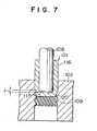
- Fig. 7 is an illustration of an essential part of another embodiment of the invention, applied to a formation of a helical involute spline in the outer cylindrical surface of a cylindrical part.
- a cylindrical blank 101 is provided at its one end (lower end in this case) with a bottom portion having a thickness large enough to withstand a shearing force which is applied thereto during the processing.
- the blank 101 is supported at the outer peripheral surface of the cylindrical portion thereof by a die 102.
- a stepped outer cylindrical portion 120 of a diameter substantially equal to or smaller than the inside diameter of the helical involute spline 109 formed in the inner peripheral surface of the die 102 is beforehand provided in the outer cylindrical surface of the cylindrical portion 116 adjacent to the bottom thereof.
- the stepped outer cylindrical portion 120 has an axial depth substantially equal to or smaller than that of the inner bottom surface of the bottom 115.
- the stepped outer cylindrical portion 120 has an axial depth smaller than that of the inner bottom surface by a length i.
- the die apparatus itself is not shown because it is materially identical to that shown in Fig. 2 for processing the inner cylindrical surface, except that the processing part, i.e. the involute helical spline, is formed in the inner peripheral surface of the die insteadly of the outer peripheral surface of the punch.
- the die 102 is mounted on the stationary base in the same manner as that in the embodiment shown in Fig. 2.
- a punch 108 is mounted rotatably on the movable base through thrust bearings, as in the case of the embodiment shown in Fig. 2
- the movable base is moved to press the punch 108 into the bore of the cylindrical portion 116 through the open end of the latter against the bottom 115. Since the blank 101 is pressed downwardly by the punch 118 which is carried rotatably, the blank 101 is driven into the die 102 while being rotated along the helical angle of the involute spline 109 formed in the inner peripheral surface of the die 102. Meanwhile, a helical involute spline is formed in the portion of the outer cylindrical surface of the cylindrical portion above the stepped outer cylindrical portion 120, by a plastic deformation effected by the involute spline 109 in the inner peripheral surface of the die 102.
- a helical involute spline is formed in the outer cylindrical surface of the cylindrical portion 116 in confirmity with the helical involute spline 109 formed in the die 102 by the plastic work.
- the material of the cylindrical portion 116 is kept under a complete tensed condition as in the case of the processing of the inner cylindrical surface. It is, therefore, possible to drive the punch with a reduced force, which in turn provides the same advantages as those achieved in the processing of the inner cylindrical surface, i.e. the prevention of seizure and the enhancement of dimensional precision of the processing.
- part having grooves or teeth in the cylindrical surface involves not only cylindrical parts having supporting portions but also such cylindrical parts as having no substantial supporting portion and the cylindrical parts having a constant diameter of outer peripheral surface.
- the supporting portion is beforehand formed on the blank and then removed by a suitable method after the plastic work. Needless to say, it is possible to make use of a supporting portion of the cylindrical part if the part inherently has such a supporting portion.
Landscapes
- Engineering & Computer Science (AREA)
- Mechanical Engineering (AREA)
- Forging (AREA)
Applications Claiming Priority (2)
| Application Number | Priority Date | Filing Date | Title |
|---|---|---|---|
| JP59824/81 | 1981-04-22 | ||
| JP56059824A JPS57175043A (en) | 1981-04-22 | 1981-04-22 | Inside diameter shape working method of cylindrical parts |
Publications (3)
| Publication Number | Publication Date |
|---|---|
| EP0064197A2 true EP0064197A2 (fr) | 1982-11-10 |
| EP0064197A3 EP0064197A3 (en) | 1983-07-20 |
| EP0064197B1 EP0064197B1 (fr) | 1986-09-17 |
Family
ID=13124357
Family Applications (1)
| Application Number | Title | Priority Date | Filing Date |
|---|---|---|---|
| EP82103225A Expired EP0064197B1 (fr) | 1981-04-22 | 1982-04-16 | Procédé d'usinage d'une surface cylindrique |
Country Status (5)
| Country | Link |
|---|---|
| US (1) | US4452060A (fr) |
| EP (1) | EP0064197B1 (fr) |
| JP (1) | JPS57175043A (fr) |
| AU (1) | AU536304B2 (fr) |
| DE (1) | DE3273280D1 (fr) |
Cited By (7)
| Publication number | Priority date | Publication date | Assignee | Title |
|---|---|---|---|---|
| EP0322770A3 (en) * | 1987-12-26 | 1990-09-05 | M. H. Center, Ltd. | Method and apparatus for plastically forming helical internal gears and helical gears |
| CN103381467A (zh) * | 2013-07-11 | 2013-11-06 | 江苏森威精锻有限公司 | 一种台阶类锻件开合模成形方法 |
| DE102013225666A1 (de) | 2013-12-11 | 2015-06-11 | Volkswagen Aktiengesellschaft | Verfahren zur Herstellung einer Welle-Nabe-Fügeverbindung und Welle-Nabe-Fügeverbindung oder Nockenwelle |
| CN105964860A (zh) * | 2016-06-30 | 2016-09-28 | 娄土岭 | 一种离合器冷挤压模具与使用方法 |
| CN105964861A (zh) * | 2016-06-30 | 2016-09-28 | 娄土岭 | 一种离合器锻压模具与使用方法 |
| CN109420733A (zh) * | 2017-08-28 | 2019-03-05 | 丰田自动车株式会社 | 齿轮的锻造成形方法及齿轮的锻造成形装置 |
| CN111112541A (zh) * | 2018-10-31 | 2020-05-08 | 丰田自动车株式会社 | 用于锻造齿轮的方法和设备 |
Families Citing this family (12)
| Publication number | Priority date | Publication date | Assignee | Title |
|---|---|---|---|---|
| IT1214528B (it) * | 1986-09-23 | 1990-01-18 | Aquila Piombo Per Caccia E Tir | Procedimento per la realizzazione di un polo o terminale di batteria elettrica, apparecchiatura per attuare tale procedimento, nonche'polo o terminale di batteria elettrica cosi' ottenuto. |
| JPS63149034A (ja) * | 1986-12-15 | 1988-06-21 | Hitachi Ltd | インターナルギヤの製造方法 |
| US5465597A (en) * | 1994-07-18 | 1995-11-14 | Ford Motor Company | Extrusion forming of internal helical splines |
| US5551270A (en) * | 1994-07-18 | 1996-09-03 | Ford Motor Company | Extrusion forming of internal helical splines |
| US5732586A (en) * | 1996-09-19 | 1998-03-31 | Ford Global Technologies, Inc. | Cold extrusion for helical gear teeth |
| EP1005932A3 (fr) * | 1998-11-13 | 2001-08-29 | SMS Eumuco GmbH | Procédé et dispositif pour la formation plastique d'un cylindre creux à denture intérieure |
| US6339976B1 (en) | 1999-11-12 | 2002-01-22 | Chalmer C. Jordan | Tool for removing damaged fasteners and method for making such tool |
| JP2004034037A (ja) * | 2002-06-28 | 2004-02-05 | Aisin Aw Co Ltd | 内スプライン部材及びその製造方法 |
| US6729208B1 (en) | 2002-10-29 | 2004-05-04 | Aj Manufacturing Co., Inc. | Tool for removing fasteners |
| KR100927838B1 (ko) | 2007-10-02 | 2009-11-23 | 강태흥 | 냉간단조용 금형의 유닛구조 |
| JP5025685B2 (ja) * | 2009-05-25 | 2012-09-12 | 中国電力株式会社 | 清掃確認方法 |
| CA2877173C (fr) * | 2012-07-05 | 2020-08-25 | Magna Powertrain Of America, Inc. | Formation de cannelures helicoidales |
Family Cites Families (8)
| Publication number | Priority date | Publication date | Assignee | Title |
|---|---|---|---|---|
| DE305023C (fr) * | ||||
| FR375701A (fr) * | 1906-09-20 | 1907-07-20 | Johann Ludwig Heinrich Tuengel | Bouton de vetement avec partie en forme de cosse, garantissant les fils d'attache |
| US1225915A (en) * | 1913-07-31 | 1917-05-15 | George W Bowen | Process for making grease-cup bodies. |
| US1985833A (en) * | 1930-12-20 | 1934-12-25 | Berlin Karisruher Ind Werke A | Method of making grooved sleeves |
| DE622352C (de) * | 1933-05-07 | 1935-11-26 | Fritz Werner Akt Ges | Maschine zum selbsttaetigen Eindruecken von Gewinde in Rotationskoerper aus Blech |
| DE1062091B (de) * | 1954-06-18 | 1959-07-23 | Friedrich Berges Fabrik Fuer K | Einsenkstempel zum Herstellen der Negativform gerader oder schraubenfoermiger Verzahnungen von Stirnzahnraedern |
| GB1382827A (en) * | 1971-04-01 | 1975-02-05 | Lucas Industries Ltd | Method of and apparatus for forming splines |
| US4200235A (en) * | 1978-04-03 | 1980-04-29 | Victor Equipment Company | Multiple piece torch tip |
-
1981
- 1981-04-22 JP JP56059824A patent/JPS57175043A/ja active Granted
-
1982
- 1982-04-15 US US06/368,663 patent/US4452060A/en not_active Expired - Fee Related
- 1982-04-16 DE DE8282103225T patent/DE3273280D1/de not_active Expired
- 1982-04-16 EP EP82103225A patent/EP0064197B1/fr not_active Expired
- 1982-04-21 AU AU82879/82A patent/AU536304B2/en not_active Ceased
Cited By (7)
| Publication number | Priority date | Publication date | Assignee | Title |
|---|---|---|---|---|
| EP0322770A3 (en) * | 1987-12-26 | 1990-09-05 | M. H. Center, Ltd. | Method and apparatus for plastically forming helical internal gears and helical gears |
| CN103381467A (zh) * | 2013-07-11 | 2013-11-06 | 江苏森威精锻有限公司 | 一种台阶类锻件开合模成形方法 |
| DE102013225666A1 (de) | 2013-12-11 | 2015-06-11 | Volkswagen Aktiengesellschaft | Verfahren zur Herstellung einer Welle-Nabe-Fügeverbindung und Welle-Nabe-Fügeverbindung oder Nockenwelle |
| CN105964860A (zh) * | 2016-06-30 | 2016-09-28 | 娄土岭 | 一种离合器冷挤压模具与使用方法 |
| CN105964861A (zh) * | 2016-06-30 | 2016-09-28 | 娄土岭 | 一种离合器锻压模具与使用方法 |
| CN109420733A (zh) * | 2017-08-28 | 2019-03-05 | 丰田自动车株式会社 | 齿轮的锻造成形方法及齿轮的锻造成形装置 |
| CN111112541A (zh) * | 2018-10-31 | 2020-05-08 | 丰田自动车株式会社 | 用于锻造齿轮的方法和设备 |
Also Published As
| Publication number | Publication date |
|---|---|
| JPS57175043A (en) | 1982-10-27 |
| AU8287982A (en) | 1982-11-25 |
| US4452060A (en) | 1984-06-05 |
| AU536304B2 (en) | 1984-05-03 |
| DE3273280D1 (en) | 1986-10-23 |
| JPS6245012B2 (fr) | 1987-09-24 |
| EP0064197A3 (en) | 1983-07-20 |
| EP0064197B1 (fr) | 1986-09-17 |
Similar Documents
| Publication | Publication Date | Title |
|---|---|---|
| US4452060A (en) | Method of processing cylindrical surface | |
| US4845972A (en) | Method for working the ends of steel pipe by upsetting and pressing | |
| KR930001088B1 (ko) | 헬리컬인터널기어 및 헬리컬기어의 소성 가공방법 및 그의 가공장치 | |
| GB1438220A (fr) | ||
| KR100560075B1 (ko) | 랙축의제조방법및장치 | |
| US3835686A (en) | Method of manufacturing a steel component having a head part and a hollow shank part | |
| AU7552796A (en) | Apparatus and method for forging a pinion gear with a near net shape | |
| JP2847024B2 (ja) | 段付き部品の鍛造金型及び段付き部品の鍛造方法 | |
| AU6890494A (en) | A method of making a mandrel for blind rivets | |
| CN220646435U (zh) | 斜花齿圆螺母及其成型装置 | |
| US4461162A (en) | Forging of conical liners | |
| US5211048A (en) | Method of forming shaped configuration at end of long element | |
| EP0158883A2 (fr) | Bague de roulement extérieure d'un joint universel à gorges de roulement croisées | |
| FR2384567A1 (fr) | Procede de fabrication d'elements de liaison ou d'articulation | |
| US3538793A (en) | Extrusion of helically fluted cutting tools | |
| JPH09168997A (ja) | パンチング機械用の回転機構付き金型 | |
| EP0755734B1 (fr) | Procédé pour l'extrusion à froid d'une roue dentée conique avec arbre de rotation intégral et roue dentée conique ainsi obtenue | |
| EP0143579A1 (fr) | Eléments de fixation du type boulon à utiliser pour outils mûs par force et procédé de leur fabrication | |
| JP2887585B2 (ja) | 筒部を有する板金製部材の内鍔部形成方法 | |
| KR20180082382A (ko) | 냉간 배압단조공법을 통한 플랜지형 허브클러치 제조방법 | |
| EP0003443A1 (fr) | Perfectionnements relatifs aux paliers de roulement | |
| KR20180029301A (ko) | 냉간 배압단조공법을 통한 플랜지형 허브클러치 제조방법 | |
| JPH0679393A (ja) | 鍛造装置 | |
| JP3056094B2 (ja) | ハスバ歯車加工装置及び加工方法 | |
| SU1268267A2 (ru) | Способ получени отверстий с фасками в толстолистовых заготовках |
Legal Events
| Date | Code | Title | Description |
|---|---|---|---|
| PUAI | Public reference made under article 153(3) epc to a published international application that has entered the european phase |
Free format text: ORIGINAL CODE: 0009012 |
|
| AK | Designated contracting states |
Designated state(s): CH DE FR GB IT NL SE |
|
| PUAL | Search report despatched |
Free format text: ORIGINAL CODE: 0009013 |
|
| AK | Designated contracting states |
Designated state(s): CH DE FR GB IT LI NL SE |
|
| 17P | Request for examination filed |
Effective date: 19830727 |
|
| GRAA | (expected) grant |
Free format text: ORIGINAL CODE: 0009210 |
|
| AK | Designated contracting states |
Kind code of ref document: B1 Designated state(s): CH DE FR GB IT LI NL SE |
|
| REF | Corresponds to: |
Ref document number: 3273280 Country of ref document: DE Date of ref document: 19861023 |
|
| ET | Fr: translation filed | ||
| ITF | It: translation for a ep patent filed | ||
| PLBE | No opposition filed within time limit |
Free format text: ORIGINAL CODE: 0009261 |
|
| STAA | Information on the status of an ep patent application or granted ep patent |
Free format text: STATUS: NO OPPOSITION FILED WITHIN TIME LIMIT |
|
| 26N | No opposition filed | ||
| PGFP | Annual fee paid to national office [announced via postgrant information from national office to epo] |
Ref country code: FR Payment date: 19910325 Year of fee payment: 10 |
|
| PGFP | Annual fee paid to national office [announced via postgrant information from national office to epo] |
Ref country code: GB Payment date: 19910402 Year of fee payment: 10 |
|
| ITTA | It: last paid annual fee | ||
| PGFP | Annual fee paid to national office [announced via postgrant information from national office to epo] |
Ref country code: NL Payment date: 19910430 Year of fee payment: 10 |
|
| PGFP | Annual fee paid to national office [announced via postgrant information from national office to epo] |
Ref country code: CH Payment date: 19910626 Year of fee payment: 10 |
|
| PGFP | Annual fee paid to national office [announced via postgrant information from national office to epo] |
Ref country code: DE Payment date: 19910628 Year of fee payment: 10 |
|
| PGFP | Annual fee paid to national office [announced via postgrant information from national office to epo] |
Ref country code: SE Payment date: 19920306 Year of fee payment: 11 |
|
| PG25 | Lapsed in a contracting state [announced via postgrant information from national office to epo] |
Ref country code: GB Effective date: 19920416 |
|
| PG25 | Lapsed in a contracting state [announced via postgrant information from national office to epo] |
Ref country code: LI Effective date: 19920430 Ref country code: CH Effective date: 19920430 |
|
| PG25 | Lapsed in a contracting state [announced via postgrant information from national office to epo] |
Ref country code: NL Effective date: 19921101 |
|
| GBPC | Gb: european patent ceased through non-payment of renewal fee | ||
| NLV4 | Nl: lapsed or anulled due to non-payment of the annual fee | ||
| PG25 | Lapsed in a contracting state [announced via postgrant information from national office to epo] |
Ref country code: FR Effective date: 19921230 |
|
| REG | Reference to a national code |
Ref country code: CH Ref legal event code: PL |
|
| PG25 | Lapsed in a contracting state [announced via postgrant information from national office to epo] |
Ref country code: DE Effective date: 19930101 |
|
| REG | Reference to a national code |
Ref country code: FR Ref legal event code: ST |
|
| PG25 | Lapsed in a contracting state [announced via postgrant information from national office to epo] |
Ref country code: SE Effective date: 19930417 |
|
| EUG | Se: european patent has lapsed |
Ref document number: 82103225.7 Effective date: 19931110 |