EP0064272A2 - Procédé et appareil pour l'emballage d'un matériau solide - Google Patents
Procédé et appareil pour l'emballage d'un matériau solide Download PDFInfo
- Publication number
- EP0064272A2 EP0064272A2 EP82103625A EP82103625A EP0064272A2 EP 0064272 A2 EP0064272 A2 EP 0064272A2 EP 82103625 A EP82103625 A EP 82103625A EP 82103625 A EP82103625 A EP 82103625A EP 0064272 A2 EP0064272 A2 EP 0064272A2
- Authority
- EP
- European Patent Office
- Prior art keywords
- bag
- taking
- solid material
- bags
- taking member
- Prior art date
- Legal status (The legal status is an assumption and is not a legal conclusion. Google has not performed a legal analysis and makes no representation as to the accuracy of the status listed.)
- Granted
Links
Images


Classifications
-
- B—PERFORMING OPERATIONS; TRANSPORTING
- B65—CONVEYING; PACKING; STORING; HANDLING THIN OR FILAMENTARY MATERIAL
- B65B—MACHINES, APPARATUS OR DEVICES FOR, OR METHODS OF, PACKAGING ARTICLES OR MATERIALS; UNPACKING
- B65B43/00—Forming, feeding, opening or setting-up containers or receptacles in association with packaging
- B65B43/12—Feeding flexible bags or carton blanks in flat or collapsed state; Feeding flat bags connected to form a series or chain
- B65B43/14—Feeding individual bags or carton blanks from piles or magazines
-
- B—PERFORMING OPERATIONS; TRANSPORTING
- B65—CONVEYING; PACKING; STORING; HANDLING THIN OR FILAMENTARY MATERIAL
- B65B—MACHINES, APPARATUS OR DEVICES FOR, OR METHODS OF, PACKAGING ARTICLES OR MATERIALS; UNPACKING
- B65B43/00—Forming, feeding, opening or setting-up containers or receptacles in association with packaging
- B65B43/12—Feeding flexible bags or carton blanks in flat or collapsed state; Feeding flat bags connected to form a series or chain
- B65B43/14—Feeding individual bags or carton blanks from piles or magazines
- B65B43/16—Feeding individual bags or carton blanks from piles or magazines by grippers
-
- B—PERFORMING OPERATIONS; TRANSPORTING
- B65—CONVEYING; PACKING; STORING; HANDLING THIN OR FILAMENTARY MATERIAL
- B65B—MACHINES, APPARATUS OR DEVICES FOR, OR METHODS OF, PACKAGING ARTICLES OR MATERIALS; UNPACKING
- B65B43/00—Forming, feeding, opening or setting-up containers or receptacles in association with packaging
- B65B43/26—Opening or distending bags; Opening, erecting, or setting-up boxes, cartons, or carton blanks
- B65B43/34—Opening or distending bags; Opening, erecting, or setting-up boxes, cartons, or carton blanks by internal pressure
Definitions
- This invention relates to a solid material packing method in which solid material such as ham is packed in a film bag, and to apparatus for carrying out the method.
- Futhermore there is also ⁇ known a solid material packing method in which a number of film bags are stuck to a piece of adhesive tape in such a manner that they overlap one another, and the film bags are supplied with material one after another each time a packing cycle is completed, utilizing a packing cycle comprising the opening of a film bag, putting solid material into the film bag and removing the film bag, so that solid materials are continuously packed.
- this latter method is disadvantageous in that both the forming of the assembly of film bags stuck to the piece of adhesive tape and the setting of the assembly of film bags are troublesome,
- Solid material packing machines also differ in their particular means for supplying the material into the bag.
- a relatively thick, cylindrical object In the case where a relatively thick, cylindrical object is to be packed into a bag, it is common to place a sufficiently opened bag in front of the front end portion of a cylindrical chute, and the material is then delivered into the bag through the chute.
- An object of this invention is to provide solid material packing method and apparatus in which the above-described drawbacks accompanying a conventional solid material packing method can be eliminated or at least substantially reduced and solid-material can be automatically packed with high efficiency.
- a packing method comprising the steps of transporting one of a plurality of bags from a storage location to a packing location and inserting material into said bag, characterized in that the transporting step comprises: pressing against said one bag with a taking member having at least one exposed adhesive surface thereon for adhering to said bags; and moving said taking member from a first position in which it presses against said one bag at said storage location to a second position in which it holds said bag at said packing location.
- a packing apparatus in which one of a plurality of bags is transported from a storage location to a packing location and material is then inserted into said bag, characterized by a taking member having at least one adhesive surface thereon, said taking member being pivotable between a first position in which said adhesive surface presses against and adheres to said one bag at said storage location and a second position at which it holds said bag at said packing location.
- a solid material packing method and apparatus in which a plurality of plastic film bags, each of which has an opening at one end and a sealed or knotted bottom at the other end, are stacked upon one another to form a stack of plastic film bags which are supported by a support member at at least two points near the opening so that the bags can be taken out.
- the support member of the stack of plastic film bags is preferably detachably set on mounting means, and the bags are taken out of the stack of film bags one at a time by sticking and taking means.
- the sticking and taking means preferably comprises: pressing and sticking members which operate to take out the top one in the stack of film bags by causing adhesive tapes to press against and stick to the top film bag at at least two points near the opening thereof and to release the top film bag when a solid material is packed therewith; means for feeding the adhesive tapes to replace the pressing and sticking surfaces thereof whenever one film bag is taken out; and a support for supporting the pressing and sticking members.
- the opening of the film bag taken out is:: set at a packing position in solid material supplying means by a movable sticking, taking and supplying means which is obtained by mounting the sticking and taking means on another support.
- the film bag is inflated by jetting air to the opening of the film.bag.thus taken out, and the film bag is released from the sticking and taking means included in the sticking, taking and supplying means by putting a solid material into the film bag through the opening thereof, to thereby obtain a packed solid material.
- a more specific feature of the invention resides in a pair of conduit-shaped holding plates which are so designed as to perform all of the operations of holding a material to be packed, holding the bag open and placing the material into the bag.
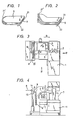
- Fig. 1 shows a bag cassette 9 comprising a stack of film bags 6 which are bound together with a support member, e.g., a plastic fastener 22.
- a support member e.g., a plastic fastener 22.
- Each film bag 6 has a sealed bottom 21' at one end, and an opening 21 at the opposite end.
- Fig. 2 shows another example of the bag cassette 9 which is different from that in Fig. 1 in that each film bag has a knotted bottom 21" instead of a sealed bottom.
- Fig. 3 is a plan view of a solid material packing machine according to a preferred embodiment of this invention.
- Fig. 4 is a side view of the machine as viewed in the direction if the arrow IV in Fig. 3.
- Fig. 5 is also a side view of the machine as viewed in the direction of the arrow V in Fig. 3.
- the stack of film bags, or the bag cassette 9, is detachably mounted on a mounting means, in the form of a mounting stand 8. More specifically, the bag cassette 9 is mounted on the mounting stand 8 by laterally inserting the fastener 22 into a dovetail groove 15 formed in the mounting stand 8.
- the dovetail groove 15 is formed in the front surface of the mounting stand 8 in such a manner that it extends from one side of the stand to the other.
- the stand 8 may be wide enough to accomodate two bag cassettes, in which. case a bag cassette to be used next may be provided beside a bag cassette being used.
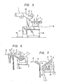
- Figs. 6, 7 and 8 are diagrams for a description of the operation of the solid material packing machine.
- the bag cassette 9 which is a stack of film bags is set on the mounting stand 8.
- reference numeral 1 designates a solid material sliding stand on which solid material is placed. The solid material thus placed slides down the stand 1 into an awaiting bag as shown in Fig. 8.
- a sticking, taking and supplying means comprises a stick-' ing and taking means mounted on a support, and comprises a take-up unit 7 in Fig. 6.
- the take-up unit 7 can be turned about a vertical axis from a position A where a solid material supplying means is positioned as shown in Fig. 3 to a position B.
- the unit 7 is shown in solid outline in its positon B in Fig. 4, while the dotted outline designated by reference numeral 7' in Fig. 4 represents position A.
- the take-up unit 7 In the position B, the take-up unit 7 can be moved in the direction of the arrow R in Fig. 3, in response to an operation signal from a foot switch 16, so as to be ready for taking out the top one 6' of the stack of film bags.
- a pivoting sticker 3 which is the sticking and taking means of the take-up unit 7 has at least two sticking tape members 5 at its outer end.
- the sticker 3 With the unit 7 in position B, the sticker 3 is pivotted counterclockwise in Fig. 4 to press against and stick to the topmost bag 6'.
- the sticker 3 is pivotted clockwise so that the sticking tape members 5 are moved from a position D (Fig. 4) where they press against the bag cassette 9 to a position C (Fig. 4) to which they bring the topmost film bag 6 (i.e., the sticking tape members 5 are swung from the position as shown in Fig. 6 to the position as shown in Fig. 7 while carrying a film bag designated by reference numeral 13 in Fig. 7).
- the take-up unit 7 is turned about a vertical axis while moving laterally from the position B to the position A shown at 7' in Fig. 4.
- the opening 21 of the film bag 6 is directed to the solid material sliding stand 1 and a sloping stand 20 extending therefrom, as shown in Fig. 5 or 8.
- an air nozzle 12 disposed below the sloped stand 20 as shown in Fig. 8 jets air into the bag 6 through its opening 21, to inflate the film bag 6.
- the inflation of the bag is detected by a conventional detecting means such as an optical device.
- a solid material to be packed is put into the inflated bag through a solid material supplying funnel 2, and the film bag stuck to the sticking tape member 5 is released from the latter 5, preferably by the weight of the solid material, when the solid material is put into the bag so that the film bag containing the solid material is dropped onto the conveying means 19.
- reference numeral 10 designates a supporting stand; and 11, a power source.
- a film bag retaining member 14 is preferably provided in the sticking and taking section, which retaining member 14 slides on the open ends of film bags to ensure that only one film bag is taken out whenever the tape heads 17 swing in a vertical plane (Figs. 6 and 7).
- the film bag transport operation of the sticking and taking section is as follows: after the sticking tape members have been moved from the position D to the position C, and in response to a signal indicating this movement, the take-up unit 7 is moved from the position B to the position A ( F ig.
- the sticker 3, which is the.pressing and sticking means of the take-up unit 7, preferably has at least two sticking tape members 5 at the top, as already described herein.
- Each sticking tape member 5 is made up of an adhesive tape and a tape head 17 which serves as a support in pressing against the cassette bag. When necessary, the sticking area can be changed by replacing the tape head 17.
- the sticking tape member is so designed to have a new sticking surface at all times, as will be described later, by feeding of the adhesive tape. More specifically, whenever a film bag 6 is taken out, the adhesive tape is advanced 2 to 10 mm, preferably 2 to 3 mm, by a one-way clutch mechanism or the like.
- the adhesive tape may be advanced prior to the next swinging operation of the take-up unit 7.
- the adhesive tape is advanced during movement of the unit from position C to position D.
- the adhesive tape of the sticking tape member 5 may be any one of a variety of adhesive tapes, and a commercially available adhesive tape in the form of a roll may be employed as the adhesive tape of the sticking tape member 5. It is desirable to provide an. adjusting handle 4 so that the distance between the two sticking tape members 5 can be adjusted according to the width of a film bag with the inflation of a film bag taken into consideration. Furthermore, in order that the sticking area of the adhesive tape , to a film bag can be adjusted according to the weight of a solid material to be packed, it is desirable that the pressing area of the tape head 17, which serves as the support in pressing the adhesive tape against the bag cassette, is adjustable. In this conncetion, the replacement of the tape head 17 may be the most convenient way of adjusting the pressing area.
- the adhesive tape may be supplied from an adhesive tape supply reel 23, caused to pass around the tape head 17, and can then be wound on a winding reel 24.
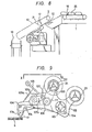
- Fig. 9 is a side view of a specific preferred example of a sticking and taking device according to this invention.
- Fig. 10 is a view in the direction of the arrow X-X in Fig. 9.
- reference numeral 101 designates a rotary shaft; 102, a base plate which is secured to a suitable portion of the rotary shaft 101 in such a manner that it is perpendicular to the latter 101; and 23, the supply reel on which an adhesive tape roll to be used is mounted.
- the adhesive tape roll may be a commercially available cellophane tape roll as described above.
- reference numeral 104 designates guide rollers for introducing the tape to a taking head 17 which can be replaced by one different in tip area and has guides 17a on both sides of the head 17; 106 and 107, pinch rolls, the pinch roll 106 being turned intermittently by a drive shaft 106a, and the pinch roll 107 being pressed against the pinch roll 106 by a coil spring 107B which is elastically connected to a lever 107a; and 24, a winding reel for winding the used tape.
- ratchet unit 110 (Fig. 10) provided on the rear side of the base plate 102 is mounted on the shaft 106a of the pinch roll 106, and a lever 109 extended from the ratchet
- the pinch roll 106 is turned intermittently with suitable timing by engaging the lever 109 during counterclockwise rotation of the plate 102.
- the taking head 17 is pressed against, adheres to and carries away a bag out of a stack of bags 6 to a predetermined position and then returns to its original position.
- the lever 109 is turned through a predetermined angle preferably during the downward stroke (counterclockwise) of the plate 102, by engaging the free end of the lever 109 with an abutment protrusion (not shown), as a result of which the pinch roll 106 is turned slightly to'feed the tape about 5 mm, the exact feed amount being adjustable in accordance with a number of factors including, e.g., the sticking area of the head 17.
- the ⁇ top of the taking head 17 is maintained adhesive at all times.
- the winding reel 24 is turned by a belt 113 which is laid over a pulley 111 connected to the shaft 106a and over a pulley 112 connected to the shaft 24a.
- a slip means is necessary since the diameter of the tape wound on the winding reel 24 will change with time.
- a conventional brake means is provided for the reel 23 so that tension is maintained in the tape at all times.
- the surfaces of the rolls are preferably finely knurled in order to prevent adhesion between the rolls and the tape; however, it is desirable that the materials of the rolls be taken into account in determining the degree and the amount of knurling.
- a bag or the like is taken out by adhering to twopoints near the mouth thereof.
- the bag thus taken out is moved to a predetermined position, as described above, where it is inflated by jetting air towards its mouth and, under this condition, a material to be packed is put into the bag.
- the solid material supplying funnel in the solid material supplying section namely, an assist funnel assembly 2
- the funnel assembly 2 can be replaced according to the size and configuration of a solid material to be packed.
- the funnel assembly 2 is used to positively put solid material into an inflated film bag.
- the funnel assembly 2 is preferably made up of a pair of funnel pieces as shown in Fig. 3, and the funnel pieces are so set that the front ends thereof are closed to hold a solid material.
- the funnel assembly 2 is moved towards the film bag.
- the front ends fo the funnel pieces are inserted into the film bag, the front ends are opened to hold open the open end of the film bag while allowing the solid material to drop into the film bag.
- the air which is at first not applied to the opening of the film bag will follow along the upper surface of the film bag to form a negative pressure thereon, to thereby open the film bag.
- the air is positively introduced into the film bag.
- the front ends of the funnel pieces can be made slippery by the fat of the meat, and accordingly the solid materials may drop down the funnel assembly before it is intended to put them into the film bags. If the bag opening has not been positively secured by the funnel assembly, the meat may not pass into the bag properly.
- means for supporting a film bag such as knurled members or needle-like protrusions, are provided on the outside surfaces of the funnel pieces which are brought into engagement with the film bag.
- a solid material supplying conveyor 8 is provided on the solid material sliding stand 1 for supplying solid materials.
- the conveyor 8 operates to supply the solid materials 25 one at a time in association with the film bag inflating operation described before.
- a film bag, after being filled with a solid material, is released from the funnel assembly and dropped onto the conveying means 19, so that it is delivered to the next process, for instance, for cacuum packing.
- an automatic operation control device which uses a conventional optical detecting mechanism to allow the operation of the sticking, taking and supplying section, the operation of the film bag inflating section and the operation of the solid material supplying section to coordinate with one another in response to the operation of the foot switch 16.
- Fig. 11 is a side view showing the essential components of a solid material supplying device according to a preferred embodiment of the invention.
- Fig. 12 and 13 are views in the direction of the arrow XII-XII in Fig. 11.
- reference numeral 201 designates a stationary board which is fixedly secured to a machine body in such a manner that it is inclined; 202, a post which is embedded upright in the stationary board 201; 203, an oil pressure or air pressure cylinder; and 204, a slide board which is slidable on the stationary board 201.
- Another post 205 is embedded upright in the slide board 204, and is coupled to the shaft 206a of a piston 206 which is fitted in cylinder 203.
- a plurality of pins 207 are embedded upright in the stationary board 201, and are slidably engaged with groove cams 208 which are formed in the slide board 204.
- reference numeral 6 designates a bag; and 2, a conduit-shaped holding plate which is secured to the flange 204a of the slide board 204.
- Fig. 12 is a view in the direction of the arrow XI I -XII in Fig. 11, showing one of the pair of units which form the solid material supplying device.
- the device is ready for operation. That is, the piston 206 is moved to the right in Fig. 12.
- One pair of holding plates 2 are so set that the front ends thereof are closed to hold a solid material 25 to be packed.
- Fig. 13 shows the solid material 25 which is being delivered into the bag 6.
- the piston 206' is moved to the left so that the slide board 204 together with the holding plate 2 is moved towards the bag 6.
- the holding plate (plates) 2 is moved into the bag 6, the pins 207 slide along the cam grooves 208 to the bent portions 208' thereof.
- the slide boards 204 are opened outwardly, and simultaneously the pair of holding plates 2 are also opened outwardly, so that the folding plates 2 are set in parallel with each other to sufficiently open the mouth of the bag.
- the solid material which has until this time been held by the holding plates, is dropped into the bag by its own weight.
- reference character 2a designates a knurled piece which positively holds the bag whose mouth has been opened.
- the bag 6 is delivered to the solid material supplying device by a means described hereinabove, and it is inflated by an air jetting means such as an air nozzle to the extent that the front ends of the holding members 2 can be inserted into the bag.
- an air jetting means such as an air nozzle
- the holding plates 2 receive and hold the next solid material while retracting to the position shown in Fig. 12.
- the holding plates 2 can be readily adjusted or replaced according to the size and configuration of the solid materials to be packed.
- the solid material packing method and machine according to the preferred embodiment of the invention, stacks of film bags which can be readily loaded on or unloaded from the machine are employed. Therefore, the solid materials can be packed with high efficiency.
- the film bags are taken out by the pressing and sticking surfaces of the sticking tape members, which are new at all times, and therefore they can be positively taken out. Even unstiff film bags can be positively taken out.
- the tape handling mechanism is simple and compact in construction, and the solid material supplying device operates effectively not only to control the supply of material into the bag but also to hold the bag open. Thus, the solid materials can be packed with high efficiency.
Landscapes
- Engineering & Computer Science (AREA)
- Mechanical Engineering (AREA)
- Supplying Of Containers To The Packaging Station (AREA)
- Auxiliary Devices For And Details Of Packaging Control (AREA)
- Basic Packing Technique (AREA)
Applications Claiming Priority (6)
| Application Number | Priority Date | Filing Date | Title |
|---|---|---|---|
| JP63371/81 | 1981-04-28 | ||
| JP6337181A JPS5946849B2 (ja) | 1981-04-28 | 1981-04-28 | 固型物充「てん」方法及び装置 |
| JP71908/81 | 1981-05-20 | ||
| JP7190881U JPS6016483Y2 (ja) | 1981-05-20 | 1981-05-20 | 固型物供給装置 |
| JP7519081U JPS57188731U (fr) | 1981-05-26 | 1981-05-26 | |
| JP75190/81 | 1981-05-26 |
Publications (3)
| Publication Number | Publication Date |
|---|---|
| EP0064272A2 true EP0064272A2 (fr) | 1982-11-10 |
| EP0064272A3 EP0064272A3 (en) | 1983-01-26 |
| EP0064272B1 EP0064272B1 (fr) | 1986-12-03 |
Family
ID=27298151
Family Applications (1)
| Application Number | Title | Priority Date | Filing Date |
|---|---|---|---|
| EP82103625A Expired EP0064272B1 (fr) | 1981-04-28 | 1982-04-28 | Procédé et appareil pour l'emballage d'un matériau solide |
Country Status (10)
| Country | Link |
|---|---|
| US (1) | US4534155A (fr) |
| EP (1) | EP0064272B1 (fr) |
| AU (1) | AU551346B2 (fr) |
| BR (1) | BR8202394A (fr) |
| CA (1) | CA1208182A (fr) |
| DE (1) | DE3274536D1 (fr) |
| DK (1) | DK183282A (fr) |
| ES (1) | ES511719A0 (fr) |
| FI (1) | FI74255C (fr) |
| NZ (1) | NZ200420A (fr) |
Cited By (3)
| Publication number | Priority date | Publication date | Assignee | Title |
|---|---|---|---|---|
| NL1035060C2 (nl) * | 2008-02-21 | 2009-08-24 | Manter Internat B V | Inrichting voor het opnemen en openen van zakken. |
| WO2013075807A1 (fr) * | 2011-11-22 | 2013-05-30 | Focke & Co. (Gmbh & Co. Kg) | Procede et dispositif permettant de manipuler des sachets regroupés en paquets |
| RU2485516C1 (ru) * | 2012-02-02 | 2013-06-20 | Алексей Гаврилович Мешандин | Способ постановки реакции иммунологического анализа |
Families Citing this family (11)
| Publication number | Priority date | Publication date | Assignee | Title |
|---|---|---|---|---|
| DE3910208A1 (de) * | 1989-03-30 | 1990-10-04 | Meyer Hans H | Beutelbefuell- und schliessvorrichtung |
| US5782066A (en) * | 1997-02-21 | 1998-07-21 | Giesbrecht; Kenneth Peter | Apparatus for filling a bag with an article loaded in a tray |
| TWI286113B (en) * | 2006-02-10 | 2007-09-01 | Hon Hai Prec Ind Co Ltd | Device for packaging and incising plastic wrappers |
| DK200900512A (da) | 2009-04-21 | 2010-10-22 | Schur Technology As | Fremgangsmåde og apparat til distribution af emner i et lagerrum |
| US8122689B2 (en) | 2007-01-24 | 2012-02-28 | Schur International A/S | Method and apparatus for producing, bagging and dispensing ice |
| US9409726B2 (en) | 2010-09-17 | 2016-08-09 | Reddy Ice Technology Llc | Method and apparatus for distributing articles in a storage compartment |
| US8534034B1 (en) | 2012-08-02 | 2013-09-17 | Schur Technology A/S | Method and apparatus for distributing and storing serially produced articles in multiple storage units |
| US9562711B2 (en) | 2013-01-11 | 2017-02-07 | Reddy Ice Technology Llc | Method and apparatus for storing and dispensing bagged ice |
| CN105644855A (zh) * | 2016-01-28 | 2016-06-08 | 漳州佳龙科技股份有限公司 | 一种传动驱动的无动力胶带吸取机构及其方法 |
| US20180222616A1 (en) * | 2017-02-09 | 2018-08-09 | Walmart Apollo, Llc | Automated Opening Device for Plastic Shopping Bags on Carousels |
| CN115285438B (zh) * | 2022-08-31 | 2024-08-16 | 贵州盘江民爆有限公司 | 一种装箱设备 |
Family Cites Families (18)
| Publication number | Priority date | Publication date | Assignee | Title |
|---|---|---|---|---|
| DE683619C (de) * | 1936-11-17 | 1939-11-10 | Fr Hesser Maschinenfabrik Akt | Flachbeutelfuell- und -schliessmaschine |
| US2612738A (en) * | 1948-05-21 | 1952-10-07 | Ivers Lee Co | Method of and machine for making and filling packages for fluent substances |
| US2702150A (en) * | 1952-05-20 | 1955-02-15 | Clarence W Vogt | Apparatus for filling bags |
| FR1096132A (fr) * | 1953-04-23 | 1955-06-09 | Gebru Der Holler Maschinenfabr | Dispositif utilisable pour ouvrir des sacs pliés |
| US2973612A (en) * | 1956-02-20 | 1961-03-07 | William S Mcgowan | Bag opener |
| US3083961A (en) * | 1960-06-23 | 1963-04-02 | Pfaff Ag G M | Pickup device for use in feeding mechanism and the like |
| US3206913A (en) * | 1962-08-14 | 1965-09-21 | Albert H Ginsburg | Bag filling machine |
| DE1285381B (de) * | 1963-07-01 | 1968-12-12 | Nordischer Maschb Rudolf Baade | Vorrichtung zum Greifen von aus Folien hergestellten Beuteln |
| US3412522A (en) * | 1965-07-06 | 1968-11-26 | Carter William Co | Mechanism for successively feeding bags to a bag loading machine |
| US3471997A (en) * | 1966-06-22 | 1969-10-14 | American Packaging Corp | Packaging machine |
| FR1503836A (fr) * | 1966-10-14 | 1967-12-01 | Azolacq | Machine à ensacher |
| US3427780A (en) * | 1966-12-05 | 1969-02-18 | Philip Bock | Bag opening and closing machine |
| US3448557A (en) * | 1967-04-19 | 1969-06-10 | Spartans Ind Inc | Folding and bagging machine |
| US3430409A (en) * | 1967-04-20 | 1969-03-04 | Union Camp Corp | Automatic bag opener |
| DE2126643A1 (de) * | 1971-05-28 | 1972-12-07 | Gocking, Albert, 4742 Stromberg | Verfahren und Vorrichtung zum Auf stecken von Sacken, insbesondere Ventil sacken, auf Fullrohre von Sack Abfull maschinen |
| US4018031A (en) * | 1972-05-19 | 1977-04-19 | Marcal Paper Mills, Inc. | Article packaging machine |
| US3881410A (en) * | 1973-05-10 | 1975-05-06 | Norwood Marking & Equipment Co | Inflated bag printer having the anvil mounted on a bell crank |
| IT995630B (it) * | 1973-10-05 | 1975-11-20 | Buzzi R | Macchina per riempire e cucire automaticamente sacchi |
-
1982
- 1982-04-20 CA CA000401315A patent/CA1208182A/fr not_active Expired
- 1982-04-23 DK DK183282A patent/DK183282A/da not_active Application Discontinuation
- 1982-04-26 FI FI821442A patent/FI74255C/fi not_active IP Right Cessation
- 1982-04-26 ES ES82511719A patent/ES511719A0/es active Granted
- 1982-04-27 BR BR8202394A patent/BR8202394A/pt unknown
- 1982-04-27 US US06/372,351 patent/US4534155A/en not_active Expired - Fee Related
- 1982-04-27 NZ NZ200420A patent/NZ200420A/en unknown
- 1982-04-28 DE DE8282103625T patent/DE3274536D1/de not_active Expired
- 1982-04-28 EP EP82103625A patent/EP0064272B1/fr not_active Expired
- 1982-04-28 AU AU83066/82A patent/AU551346B2/en not_active Ceased
Cited By (5)
| Publication number | Priority date | Publication date | Assignee | Title |
|---|---|---|---|---|
| NL1035060C2 (nl) * | 2008-02-21 | 2009-08-24 | Manter Internat B V | Inrichting voor het opnemen en openen van zakken. |
| WO2013075807A1 (fr) * | 2011-11-22 | 2013-05-30 | Focke & Co. (Gmbh & Co. Kg) | Procede et dispositif permettant de manipuler des sachets regroupés en paquets |
| AU2012342913B2 (en) * | 2011-11-22 | 2016-11-03 | Focke & Co. (Gmbh & Co. Kg) | Method and device for handling bags combined into bundles |
| US9856043B2 (en) | 2011-11-22 | 2018-01-02 | Focke & Co. (Gmbh & Co. Kg) | Method and device for handling bags combined into bundles |
| RU2485516C1 (ru) * | 2012-02-02 | 2013-06-20 | Алексей Гаврилович Мешандин | Способ постановки реакции иммунологического анализа |
Also Published As
| Publication number | Publication date |
|---|---|
| ES8306062A1 (es) | 1983-05-01 |
| FI821442A0 (fi) | 1982-04-26 |
| FI74255B (fi) | 1987-09-30 |
| FI74255C (fi) | 1988-01-11 |
| AU551346B2 (en) | 1986-04-24 |
| DK183282A (da) | 1982-10-29 |
| ES511719A0 (es) | 1983-05-01 |
| EP0064272B1 (fr) | 1986-12-03 |
| FI821442L (fi) | 1982-10-29 |
| EP0064272A3 (en) | 1983-01-26 |
| CA1208182A (fr) | 1986-07-22 |
| DE3274536D1 (en) | 1987-01-15 |
| US4534155A (en) | 1985-08-13 |
| BR8202394A (pt) | 1983-04-12 |
| NZ200420A (en) | 1986-01-24 |
| AU8306682A (en) | 1982-11-04 |
Similar Documents
| Publication | Publication Date | Title |
|---|---|---|
| EP0064272B1 (fr) | Procédé et appareil pour l'emballage d'un matériau solide | |
| US5082268A (en) | Credit card dispensing and positioning apparatus | |
| US4437232A (en) | Electronic parts mounting apparatus | |
| CN101641603B (zh) | 用于移除可剥离的密封件的设备和方法 | |
| JP4202382B2 (ja) | 素材ウエブをグリップする装置 | |
| US3814343A (en) | Automatic tape loading apparatus for cassettes and the like | |
| JPS5940684B2 (ja) | ロ−ル包装装置 | |
| DK160928B (da) | Apparat til automatisk fyldning af en pose | |
| GB1524170A (en) | Apparatus for automatic insertion of valved bags on bag-filling machines for materials in granular powder or like form | |
| US3682743A (en) | Labelling machine for pressure sensitive labels | |
| CA1218042A (fr) | Mecanisme de deploiement au jet d'air pour sac souple preleve au sommet d'une pile, et extracteur transversal dudit mecanisme | |
| US6837023B1 (en) | Printer for shingled bags and method | |
| JPS61282260A (ja) | 電気部品の取扱い装置 | |
| US4310037A (en) | Apparatus for mounting valve bags to filling spouts of filling machines | |
| US3330555A (en) | Pneumatic sheet feeding platen and supply magazine | |
| JP2786537B2 (ja) | ウェブ材料ストリップのスプール巻き装置 | |
| JP2551544B2 (ja) | 充填包装機 | |
| US5483877A (en) | Cassette stacker/stamper | |
| JP2603341B2 (ja) | 自動ネガ貼り装置 | |
| JP3504714B2 (ja) | ラベル貼着装置 | |
| JP2002019751A (ja) | ラベル貼付装置 | |
| JPS5946849B2 (ja) | 固型物充「てん」方法及び装置 | |
| JPS6138223Y2 (fr) | ||
| JPS6138221Y2 (fr) | ||
| JPH0597317A (ja) | 落下するシート状体の一時保持方法及び装置 |
Legal Events
| Date | Code | Title | Description |
|---|---|---|---|
| PUAI | Public reference made under article 153(3) epc to a published international application that has entered the european phase |
Free format text: ORIGINAL CODE: 0009012 |
|
| AK | Designated contracting states |
Designated state(s): BE CH DE FR GB IT NL |
|
| PUAL | Search report despatched |
Free format text: ORIGINAL CODE: 0009013 |
|
| AK | Designated contracting states |
Designated state(s): BE CH DE FR GB IT LI NL |
|
| 17P | Request for examination filed |
Effective date: 19830324 |
|
| ITF | It: translation for a ep patent filed | ||
| GRAA | (expected) grant |
Free format text: ORIGINAL CODE: 0009210 |
|
| AK | Designated contracting states |
Kind code of ref document: B1 Designated state(s): BE CH DE FR GB IT LI NL |
|
| ET | Fr: translation filed | ||
| REF | Corresponds to: |
Ref document number: 3274536 Country of ref document: DE Date of ref document: 19870115 |
|
| PLBE | No opposition filed within time limit |
Free format text: ORIGINAL CODE: 0009261 |
|
| STAA | Information on the status of an ep patent application or granted ep patent |
Free format text: STATUS: NO OPPOSITION FILED WITHIN TIME LIMIT |
|
| 26N | No opposition filed | ||
| PGFP | Annual fee paid to national office [announced via postgrant information from national office to epo] |
Ref country code: FR Payment date: 19890412 Year of fee payment: 8 |
|
| PGFP | Annual fee paid to national office [announced via postgrant information from national office to epo] |
Ref country code: BE Payment date: 19890428 Year of fee payment: 8 |
|
| ITTA | It: last paid annual fee | ||
| PGFP | Annual fee paid to national office [announced via postgrant information from national office to epo] |
Ref country code: NL Payment date: 19890430 Year of fee payment: 8 Ref country code: GB Payment date: 19890430 Year of fee payment: 8 |
|
| PGFP | Annual fee paid to national office [announced via postgrant information from national office to epo] |
Ref country code: CH Payment date: 19890523 Year of fee payment: 8 |
|
| PGFP | Annual fee paid to national office [announced via postgrant information from national office to epo] |
Ref country code: DE Payment date: 19890630 Year of fee payment: 8 |
|
| PG25 | Lapsed in a contracting state [announced via postgrant information from national office to epo] |
Ref country code: GB Effective date: 19900428 |
|
| PG25 | Lapsed in a contracting state [announced via postgrant information from national office to epo] |
Ref country code: LI Effective date: 19900430 Ref country code: CH Effective date: 19900430 Ref country code: BE Effective date: 19900430 |
|
| BERE | Be: lapsed |
Owner name: KUREHA KAGAKU KOGYO K.K. Effective date: 19900430 |
|
| PG25 | Lapsed in a contracting state [announced via postgrant information from national office to epo] |
Ref country code: NL Effective date: 19901101 |
|
| NLV4 | Nl: lapsed or anulled due to non-payment of the annual fee | ||
| PG25 | Lapsed in a contracting state [announced via postgrant information from national office to epo] |
Ref country code: FR Effective date: 19901228 |
|
| REG | Reference to a national code |
Ref country code: CH Ref legal event code: PL |
|
| PG25 | Lapsed in a contracting state [announced via postgrant information from national office to epo] |
Ref country code: DE Effective date: 19910101 |
|
| GBPC | Gb: european patent ceased through non-payment of renewal fee | ||
| REG | Reference to a national code |
Ref country code: FR Ref legal event code: ST |