EP0064319A1 - Tube d'images en couleurs - Google Patents
Tube d'images en couleurs Download PDFInfo
- Publication number
- EP0064319A1 EP0064319A1 EP82200522A EP82200522A EP0064319A1 EP 0064319 A1 EP0064319 A1 EP 0064319A1 EP 82200522 A EP82200522 A EP 82200522A EP 82200522 A EP82200522 A EP 82200522A EP 0064319 A1 EP0064319 A1 EP 0064319A1
- Authority
- EP
- European Patent Office
- Prior art keywords
- conductors
- colour
- groups
- selection means
- display tube
- Prior art date
- Legal status (The legal status is an assumption and is not a legal conclusion. Google has not performed a legal analysis and makes no representation as to the accuracy of the status listed.)
- Granted
Links
- 239000004020 conductor Substances 0.000 claims abstract description 67
- 239000000463 material Substances 0.000 claims abstract description 9
- 238000010894 electron beam technology Methods 0.000 claims description 12
- 239000003086 colorant Substances 0.000 claims description 3
- 239000003990 capacitor Substances 0.000 description 10
- OAICVXFJPJFONN-UHFFFAOYSA-N Phosphorus Chemical compound [P] OAICVXFJPJFONN-UHFFFAOYSA-N 0.000 description 5
- 229910052751 metal Inorganic materials 0.000 description 5
- 239000002184 metal Substances 0.000 description 5
- 238000010276 construction Methods 0.000 description 4
- 239000011521 glass Substances 0.000 description 4
- 230000001627 detrimental effect Effects 0.000 description 3
- UQSXHKLRYXJYBZ-UHFFFAOYSA-N Iron oxide Chemical compound [Fe]=O UQSXHKLRYXJYBZ-UHFFFAOYSA-N 0.000 description 2
- 239000011324 bead Substances 0.000 description 2
- 239000000919 ceramic Substances 0.000 description 2
- 230000000694 effects Effects 0.000 description 2
- 239000011810 insulating material Substances 0.000 description 2
- OKTJSMMVPCPJKN-UHFFFAOYSA-N Carbon Chemical compound [C] OKTJSMMVPCPJKN-UHFFFAOYSA-N 0.000 description 1
- 239000004111 Potassium silicate Substances 0.000 description 1
- 239000004115 Sodium Silicate Substances 0.000 description 1
- 239000000853 adhesive Substances 0.000 description 1
- 230000001070 adhesive effect Effects 0.000 description 1
- 230000005540 biological transmission Effects 0.000 description 1
- 230000015572 biosynthetic process Effects 0.000 description 1
- 239000004568 cement Substances 0.000 description 1
- 238000011109 contamination Methods 0.000 description 1
- 210000003298 dental enamel Anatomy 0.000 description 1
- 239000000428 dust Substances 0.000 description 1
- 229910002804 graphite Inorganic materials 0.000 description 1
- 239000010439 graphite Substances 0.000 description 1
- 239000012535 impurity Substances 0.000 description 1
- 239000002245 particle Substances 0.000 description 1
- 229910052913 potassium silicate Inorganic materials 0.000 description 1
- NNHHDJVEYQHLHG-UHFFFAOYSA-N potassium silicate Chemical compound [K+].[K+].[O-][Si]([O-])=O NNHHDJVEYQHLHG-UHFFFAOYSA-N 0.000 description 1
- 235000019353 potassium silicate Nutrition 0.000 description 1
- 229910052911 sodium silicate Inorganic materials 0.000 description 1
- NTHWMYGWWRZVTN-UHFFFAOYSA-N sodium silicate Chemical compound [Na+].[Na+].[O-][Si]([O-])=O NTHWMYGWWRZVTN-UHFFFAOYSA-N 0.000 description 1
- 239000000725 suspension Substances 0.000 description 1
Images
Classifications
-
- H—ELECTRICITY
- H01—ELECTRIC ELEMENTS
- H01J—ELECTRIC DISCHARGE TUBES OR DISCHARGE LAMPS
- H01J29/00—Details of cathode-ray tubes or of electron-beam tubes of the types covered by group H01J31/00
- H01J29/46—Arrangements of electrodes and associated parts for generating or controlling the ray or beam, e.g. electron-optical arrangement
- H01J29/80—Arrangements for controlling the ray or beam after passing the main deflection system, e.g. for post-acceleration or post-concentration, for colour switching
- H01J29/81—Arrangements for controlling the ray or beam after passing the main deflection system, e.g. for post-acceleration or post-concentration, for colour switching using shadow masks
Definitions
- the invention relates to a colour display tube comprising in an evacuated envelope means to generate a number of electron beams, a display screen having a large number of areas luminescing in different colours, and colour selection means having a large number of apertures which associate each electron beam with luminescent areas of one colour, said colour selection means comprising first and second lens electrode means situated at a defined distance from each other.
- Such a display tube is known from United States Patent Specification 4,107,569.
- a focusing effect is exerted on the electron beams passing through each of the apertures of the colour selection means.
- Such display tubes are therefore sometimes referred to as "post-focusing tubes”.
- the colour selection takes place in a manner analogous to that in a colour display tube which is equipped with a normal shadow mask.
- a colour display tube having in an evacuated envelope means to generate a number of electron beams, a display screen having a large number of areas luminescing in different colours, and colour selection means having a large number of apertures which associate each electron beam with luminescent regions of one colour, said colour selection means comprising first and second lens electrode means situated at a defined distance from each other, is characterized in that at least one of these lens electrode means consists of a number of elongate conductors or groups of elongate conductors extending parallel to each other, which conductors or groups of conductors are interconnected via an electric resistance material.
- the discharge current of the capacitor formed in combination by the first and second lens electrode means is bounded by the resistance material which is incorporated in the electric connection path of the elongate conductors or groups of conductors.
- the energy released in the flash-.. over point per unit of time thus is too small to be able to damage the colour selection means.
- the capacitor formed by the colour selection means is divided into a number of parallel connected partial capacitors which are interconnected via resistors. The energy stored in each of the partial capacitors in the case of a flash-over within said partial capacitor may not lead to damage of the colour selection means.
- the product of the capacity of a partial capacitor and the square of the voltages difference between the first and second lens electrode means may therefore not exceed a given critical value.
- This critical value depends on the construction of the colour selection means. It can be established experimentally, however, into how many partial capacities the overall capacity of the colour selection means has to be subdivided so as not to have detrimental results of an electric flash-over. The smallest partial capacity is obtained when each of the elongate conductors is connected to another elongate conductor via a resistor. It is also possible and sometimes desirable to divide the conductors into groups of interconnected conductors and to interconnect said groups via resistors. The capacity of a partial capacitor is in this case determined by the number of elongate conductors in a group.
- the elongate conductors or groups of elongate conductors are connected to a common voltage supply conductor via an electric resistance material.
- the desired resistance values can be obtained with discrete resistors or in the form of a layer of resistance material. These resistance values are not particularly critical and depend inter alia on the dimensions of the colour selection means.
- the minimum resistance value is determined by the current strength occurring in an electric Hash-over in the flash-over point, which current strength is still permissible.
- the resistance between two adjacent elongate conductors or between two adjacent groups of elongate conductors is at least substantially 2000 Ohms.
- an upper limit is also imposed on said resistance values so as to prevent too large potential variations from occurring in the colour selection means as a result of, for example, dissipating secondary electrons which impinge on the elongate conductors.
- the resistance values are chosen to be not higher than substantially 500 x 10 3 O h m.
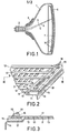
- the tube shown in Fig. 1 comprises a glass envelope 1, means 2 to generate three electron beams 3, 4 and 5, a display screen 6, colour selection means 7 and deflection coils 8.
- the electron beams 3, 4 and 5 are generated in one plane, the plane of the drawing of Fig. 1, and are deflected over the display screen 6 by means of the deflection coils 8.
- the display screen 6 consists of a large number of phosphor strips luminescing in red, green and blue the longitudinal direction of which is perpendicular to the plane of the drawing of Fig. 1. During normal operation of the tube the phosphor strips are vertical and Fig. 1 thus is a horizontal sectional view of the tube.
- the colour selection means 7 comprise a large number of apertures 9 which are shown diagrammatically only in Fig. 1.
- the three electron beams 3, 4 and 5 pass through the apertures 9 at a small angle with each other and consequently each impinge only on phosphor strips of one colour, each beam being associated with a different colour.
- the apertures 9 in the colour selection means 7 are thus very accurately positioned relative to the phosphor strips of the display screen 6.
- the colour selection means consist of first and second lens electrode means and a focusing effect is exerted on the electron beams 3, 4 and 5 passing through each of the apertures 9.
- the first and second lens electrode means for that purpose have an electric potential difference with respect to each other of approximately 2000 V.
- the first electrode means consist of a metal plate 11 having rows of apertures 9.
- the second lens electrode means consist of a number of elongate conductors 12 extending parallel to each other and kept at a distance of approximately 100 / um from the metal plate 11 by means of glass beads 13.
- the conductors 12 are positioned between the rows of apertures 9 and the beads 13 are connected by means of an enamel on the one hand to the conductors 12 and on the other hand to the plate 11, -
- the apertures 9 are 475 x 570 ⁇ m and their pitch is 775 / um so that the transmission of the colour selection means is approximately 50%
- the display screen 6 and the metal plate 11 are electrically connected and during operation of the display tube receive a voltage of approximately 25 kV while a voltage of approximately 23 kV is applied to the conductors 12.
- a quadrupole lens field is formed in each of the apertures 9 in such manner that an electron beam passing through an aperture 9 is focused in one direction and is defocused in a direction at right angles to said direction.
- an elongate spot is obtained on the display screen 6 the long axis of which is parallel to the phosphor strips on the display screen 6.
- the conductors 12 and the metal plate 11 together constitute a capacitor which discharges at such a flash-over.
- a colour selection electrode of 38 x 52 cm said capacitor has a capacity of approximately 10 nF.
- the energy stored in said capacitor at the given voltage of 2000 V is only a few tens of milli-Joules, when the conductors 12 are interconnected in a low-ohmic manner, said energy may be released in the flash-over point in fractions of a second.
- the detrimental results of an electric flash-over are restricted by interconnecting the conductors 12 in a high-ohmic manner so that the discharge current in the flash over point is limited to a permissible value.
- Figs. 2 and 3 show a possible construction with which this can be realized.
- the plate 11 comprises at its edge a step-shaped strip 14 on which a strip 15 of insulating material, for example glass or ceramic, is connected.
- the conductors 12 project beyond the plate 11 and bear on the strip 15.
- a second strip 16 of insulating material (glass or ceramic) is connected to the strip 15 by means of an adhesive 17, for example a connection cement, the conductors 12 being also connected between the strips 15 and 16.
- a voltage supply conductor 18 which is common to the conductors 12 is connected to the strip 16.
- the high-ohmic connection between the conductors 12 is obtained by means of a layer of resistance material 19 which is in the form of a suspension and which also provides a high-ohmic connection between the conductors 12 and the common supply conductor 18.
- the layer 19 in the dried condition consists of approximately 21% by weight of sodium silicate or potassium silicate, 63% by weight of iron oxide (Fe 2 0 3 ) and 16% by weight of graphite.
- a resistance of 25 x 10 3 to 100 x 10 3 Ohm is obtained between adjacent conductors 12 which restricts the current strength occurring in the case of a flash-over in the flash-over point to a few milliamperes.
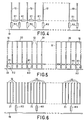
- Fig. 4 shows diagrammatically how the elongate conductors are coupled together and to the common supply conductor 18 according to the construction shown in Figs. 2 and 3.
- the resistors R 1 denote the resistance obtained by the resistance layer 19 between two adjacent conductors 12.
- the resistors R 2 indicate the resistance between a conductor 12 and the common conductor 18 obtained by the resistance layer 19.
- the resistors R 1 and R 2 are of the same order of magnitude and have a value between 25 x 10 3 and 100 x 10 3 O h m.
- this division into groups can simply be realized by providing short-circuit strips at the ends of the conductors 12 not shown in Fig. 2, which strips each connect a number of conductors to a group.
- said short-circuit strips are referenced 20.
- Another embodiment of conductors connected in groups is shown diagrammatically in Fig. 6.
- the short-circuit strips 21 shown in said figure are connected to the common supply conductors 18 via resistors R3.
- connection in groups of the conductors 12, that is to say the division into larger partial capacities of the overall capacities of the colour selection means may be necessary in connection with dust particles or other contaminations which may form a source of the formation of an electric flash-over.
- a partial capacity and therewith the energy released in the flash-over point per unit of time is then on the one hand large enough to burn away such an impurity, but on the other hand is too small to damage the colour selection means.
Landscapes
- Cathode-Ray Tubes And Fluorescent Screens For Display (AREA)
- Electrodes For Cathode-Ray Tubes (AREA)
Applications Claiming Priority (2)
| Application Number | Priority Date | Filing Date | Title |
|---|---|---|---|
| NL8102200A NL8102200A (nl) | 1981-05-06 | 1981-05-06 | Kleurenbeeldbuis. |
| NL8102200 | 1981-05-06 |
Publications (2)
| Publication Number | Publication Date |
|---|---|
| EP0064319A1 true EP0064319A1 (fr) | 1982-11-10 |
| EP0064319B1 EP0064319B1 (fr) | 1984-10-31 |
Family
ID=19837443
Family Applications (1)
| Application Number | Title | Priority Date | Filing Date |
|---|---|---|---|
| EP82200522A Expired EP0064319B1 (fr) | 1981-05-06 | 1982-05-03 | Tube d'images en couleurs |
Country Status (5)
| Country | Link |
|---|---|
| US (1) | US4473772A (fr) |
| EP (1) | EP0064319B1 (fr) |
| JP (1) | JPS57194440A (fr) |
| DE (1) | DE3261116D1 (fr) |
| NL (1) | NL8102200A (fr) |
Cited By (3)
| Publication number | Priority date | Publication date | Assignee | Title |
|---|---|---|---|---|
| WO1997006551A1 (fr) * | 1995-08-04 | 1997-02-20 | Orion Electric Co., Ltd. | Masque perfore a haute luminescence et a faible echauffement, pour tubes cathodiques, fabrication d'un ecran a l'aide de ce masque |
| US5827628A (en) * | 1995-04-29 | 1998-10-27 | Orion Electric Co., Ltd. | Method of electrographically manufacturing a luminescent screen assembly for a CRT and CRT comprising a luminescent screen assembly manufacturing by the method |
| CN1068621C (zh) * | 1995-10-12 | 2001-07-18 | 板谷博 | 电沉积用聚酰亚胺组合物及由其形成的涂层 |
Families Citing this family (5)
| Publication number | Priority date | Publication date | Assignee | Title |
|---|---|---|---|---|
| US4745330A (en) * | 1987-01-23 | 1988-05-17 | Zenith Electronics Corporation | Faceplate front assembly with improved ceramic tension mask support structure |
| US5647653A (en) * | 1995-07-26 | 1997-07-15 | Rca Thomson Licensing Corp. | Uniaxial tension focus mask materials |
| US5625251A (en) * | 1995-07-26 | 1997-04-29 | Thomson Consumer Electronics, Inc. | Uniaxial tension focus mask for color CRT and method of making same |
| US6720719B2 (en) | 2001-03-06 | 2004-04-13 | Thomson Licensing S. A. | Resistive coating for a tensioned focus mask CRT |
| DE602006016022D1 (de) * | 2006-06-21 | 2010-09-16 | Thomson Licensing | Bi-silikat-matrixbeschichtung für ein display |
Citations (3)
| Publication number | Priority date | Publication date | Assignee | Title |
|---|---|---|---|---|
| US2703850A (en) * | 1951-12-28 | 1955-03-08 | Machlett Lab Inc | Color television tube structure |
| US3742287A (en) * | 1971-04-28 | 1973-06-26 | Itt | Electron tube voltage control device |
| FR2338576A1 (fr) * | 1976-01-16 | 1977-08-12 | Philips Nv | Tube reproducteur d'images de television en couleurs et son procede de fabrication |
Family Cites Families (7)
| Publication number | Priority date | Publication date | Assignee | Title |
|---|---|---|---|---|
| NL7600420A (nl) * | 1976-01-16 | 1977-07-19 | Philips Nv | Elektrische ontladingsinrichting. |
| NL7600419A (nl) * | 1976-01-16 | 1977-07-19 | Philips Nv | Kleurenbeeldbuis en werkwijze ter vervaardiging daarvan. |
| NL7711772A (nl) * | 1977-10-27 | 1979-05-02 | Philips Nv | Kleurenbeeldbuis en werkwijze voor de vervaar- diging van een dergelijke kleurenbeeldbuis. |
| US4316126A (en) * | 1979-11-23 | 1982-02-16 | Rca Corporation | Color television picture tube with color-selection structure and method of operation thereof |
| US4350922A (en) * | 1980-06-20 | 1982-09-21 | Rca Corporation | Multicolor cathode-ray tube with quadrupolar focusing color-selection structure |
| US4311944A (en) * | 1980-06-27 | 1982-01-19 | Rca Corporation | CRT With dipolar deflection and quadrupolar-focusing color-selection structure |
| US4427918A (en) * | 1981-01-26 | 1984-01-24 | Rca Corporation | Focusing color-selection structure for a CRT |
-
1981
- 1981-05-06 NL NL8102200A patent/NL8102200A/nl not_active Application Discontinuation
-
1982
- 1982-04-19 US US06/369,959 patent/US4473772A/en not_active Expired - Fee Related
- 1982-05-03 EP EP82200522A patent/EP0064319B1/fr not_active Expired
- 1982-05-03 DE DE8282200522T patent/DE3261116D1/de not_active Expired
- 1982-05-04 JP JP57073487A patent/JPS57194440A/ja active Granted
Patent Citations (3)
| Publication number | Priority date | Publication date | Assignee | Title |
|---|---|---|---|---|
| US2703850A (en) * | 1951-12-28 | 1955-03-08 | Machlett Lab Inc | Color television tube structure |
| US3742287A (en) * | 1971-04-28 | 1973-06-26 | Itt | Electron tube voltage control device |
| FR2338576A1 (fr) * | 1976-01-16 | 1977-08-12 | Philips Nv | Tube reproducteur d'images de television en couleurs et son procede de fabrication |
Cited By (4)
| Publication number | Priority date | Publication date | Assignee | Title |
|---|---|---|---|---|
| US5827628A (en) * | 1995-04-29 | 1998-10-27 | Orion Electric Co., Ltd. | Method of electrographically manufacturing a luminescent screen assembly for a CRT and CRT comprising a luminescent screen assembly manufacturing by the method |
| WO1997006551A1 (fr) * | 1995-08-04 | 1997-02-20 | Orion Electric Co., Ltd. | Masque perfore a haute luminescence et a faible echauffement, pour tubes cathodiques, fabrication d'un ecran a l'aide de ce masque |
| US5843601A (en) * | 1995-08-04 | 1998-12-01 | Orion Electric Co., Ltd. | High-luminance-low-temperature mask for CRTS and fabrication of a screen using the mask |
| CN1068621C (zh) * | 1995-10-12 | 2001-07-18 | 板谷博 | 电沉积用聚酰亚胺组合物及由其形成的涂层 |
Also Published As
| Publication number | Publication date |
|---|---|
| EP0064319B1 (fr) | 1984-10-31 |
| JPH0227776B2 (fr) | 1990-06-19 |
| DE3261116D1 (en) | 1984-12-06 |
| US4473772A (en) | 1984-09-25 |
| NL8102200A (nl) | 1982-12-01 |
| JPS57194440A (en) | 1982-11-30 |
Similar Documents
| Publication | Publication Date | Title |
|---|---|---|
| US4107569A (en) | Color selection means comprising lens electrodes spaced by grains of insulating material | |
| US4059781A (en) | Shadow mask each aperture of which is defined by a quadrupolar lens | |
| EP0064319B1 (fr) | Tube d'images en couleurs | |
| RU2157018C2 (ru) | Цветная электронно-лучевая трубка и способ изготовления маски для нее | |
| EP0021502B1 (fr) | Tube image de télévision en couleurs | |
| US4890032A (en) | Color display tube having electrode converging means | |
| EP0058992B1 (fr) | Tube d'images en couleurs à masque focalisant | |
| US4499402A (en) | Color display tube | |
| US4128790A (en) | Cathode ray tube for displaying colored pictures | |
| US4197482A (en) | Color selection means for color display tube and method of making same | |
| US5536997A (en) | Cathode ray tube | |
| US4564786A (en) | External neck charge dissipation means for an in-line color cathode ray tube | |
| US4620134A (en) | Cathode-ray tube | |
| CA1304441C (fr) | Tube indicateur a faisceau electronique | |
| US4514658A (en) | Mesh lens focus mask for a cathode-ray tube | |
| EP0079660B1 (fr) | Tube à rayons cathodiques et ensemble de cathode pour un tel tube | |
| US4305018A (en) | Electron gun structure with electrical contact spring for color television display tube | |
| US4602186A (en) | Insulating mount for a CRT Einzel lens focus mask | |
| US6653772B1 (en) | CRT electron gun with reduced stray electron flow between electrodes | |
| GB2079038A (en) | Multicolour cathode-ray tube with quadrupolar focusing colour-selection structure | |
| US4600859A (en) | Cathode ray tube protection systems | |
| EP0333421B1 (fr) | Tubes à rayons cathodiques | |
| US3790000A (en) | Multi-electrode electron tube | |
| HUP0302583A2 (hu) | Katódsugárcső részben vezetőképes szigetelőt tartalmazó fókuszmaszkkal | |
| US4604548A (en) | Electron gun with afterglow eliminator |
Legal Events
| Date | Code | Title | Description |
|---|---|---|---|
| PUAI | Public reference made under article 153(3) epc to a published international application that has entered the european phase |
Free format text: ORIGINAL CODE: 0009012 |
|
| 17P | Request for examination filed |
Effective date: 19820503 |
|
| AK | Designated contracting states |
Designated state(s): DE FR GB IT |
|
| ITF | It: translation for a ep patent filed | ||
| GRAA | (expected) grant |
Free format text: ORIGINAL CODE: 0009210 |
|
| AK | Designated contracting states |
Designated state(s): DE FR GB IT |
|
| REF | Corresponds to: |
Ref document number: 3261116 Country of ref document: DE Date of ref document: 19841206 |
|
| ET | Fr: translation filed | ||
| PLBE | No opposition filed within time limit |
Free format text: ORIGINAL CODE: 0009261 |
|
| STAA | Information on the status of an ep patent application or granted ep patent |
Free format text: STATUS: NO OPPOSITION FILED WITHIN TIME LIMIT |
|
| 26N | No opposition filed | ||
| PGFP | Annual fee paid to national office [announced via postgrant information from national office to epo] |
Ref country code: GB Payment date: 19910501 Year of fee payment: 10 |
|
| PGFP | Annual fee paid to national office [announced via postgrant information from national office to epo] |
Ref country code: FR Payment date: 19910522 Year of fee payment: 10 |
|
| ITTA | It: last paid annual fee | ||
| PGFP | Annual fee paid to national office [announced via postgrant information from national office to epo] |
Ref country code: DE Payment date: 19910726 Year of fee payment: 10 |
|
| PG25 | Lapsed in a contracting state [announced via postgrant information from national office to epo] |
Ref country code: GB Effective date: 19920503 |
|
| GBPC | Gb: european patent ceased through non-payment of renewal fee |
Effective date: 19920503 |
|
| PG25 | Lapsed in a contracting state [announced via postgrant information from national office to epo] |
Ref country code: FR Effective date: 19930129 |
|
| PG25 | Lapsed in a contracting state [announced via postgrant information from national office to epo] |
Ref country code: DE Effective date: 19930202 |
|
| REG | Reference to a national code |
Ref country code: FR Ref legal event code: ST |