EP0064480A2 - Tréteau de sciage - Google Patents
Tréteau de sciage Download PDFInfo
- Publication number
- EP0064480A2 EP0064480A2 EP82810170A EP82810170A EP0064480A2 EP 0064480 A2 EP0064480 A2 EP 0064480A2 EP 82810170 A EP82810170 A EP 82810170A EP 82810170 A EP82810170 A EP 82810170A EP 0064480 A2 EP0064480 A2 EP 0064480A2
- Authority
- EP
- European Patent Office
- Prior art keywords
- wood
- teeth
- sawhorse
- sawing
- supports
- Prior art date
- Legal status (The legal status is an assumption and is not a legal conclusion. Google has not performed a legal analysis and makes no representation as to the accuracy of the status listed.)
- Withdrawn
Links
- 239000002023 wood Substances 0.000 claims abstract description 83
- 238000006073 displacement reaction Methods 0.000 claims description 5
- 230000005484 gravity Effects 0.000 claims description 3
- 239000002916 wood waste Substances 0.000 claims description 2
- 230000037431 insertion Effects 0.000 claims 1
- 238000003780 insertion Methods 0.000 claims 1
- 230000001681 protective effect Effects 0.000 abstract description 4
- 230000000694 effects Effects 0.000 description 3
- 241001295925 Gegenes Species 0.000 description 2
- XEEYBQQBJWHFJM-UHFFFAOYSA-N Iron Chemical compound [Fe] XEEYBQQBJWHFJM-UHFFFAOYSA-N 0.000 description 2
- 238000005520 cutting process Methods 0.000 description 2
- 238000010304 firing Methods 0.000 description 2
- 238000004519 manufacturing process Methods 0.000 description 2
- 238000005096 rolling process Methods 0.000 description 2
- 206010010219 Compulsions Diseases 0.000 description 1
- 241000265798 Prionus coriarius Species 0.000 description 1
- 229910000746 Structural steel Inorganic materials 0.000 description 1
- 239000007795 chemical reaction product Substances 0.000 description 1
- 230000006866 deterioration Effects 0.000 description 1
- 230000002349 favourable effect Effects 0.000 description 1
- 238000005246 galvanizing Methods 0.000 description 1
- 229910052742 iron Inorganic materials 0.000 description 1
- JEIPFZHSYJVQDO-UHFFFAOYSA-N iron(III) oxide Inorganic materials O=[Fe]O[Fe]=O JEIPFZHSYJVQDO-UHFFFAOYSA-N 0.000 description 1
- 238000012423 maintenance Methods 0.000 description 1
- 239000000463 material Substances 0.000 description 1
- 239000002184 metal Substances 0.000 description 1
- 229910052751 metal Inorganic materials 0.000 description 1
- 210000003205 muscle Anatomy 0.000 description 1
- 230000002250 progressing effect Effects 0.000 description 1
- 238000004080 punching Methods 0.000 description 1
Images

Classifications
-
- B—PERFORMING OPERATIONS; TRANSPORTING
- B27—WORKING OR PRESERVING WOOD OR SIMILAR MATERIAL; NAILING OR STAPLING MACHINES IN GENERAL
- B27B—SAWS FOR WOOD OR SIMILAR MATERIAL; COMPONENTS OR ACCESSORIES THEREFOR
- B27B17/00—Chain saws; Equipment therefor
- B27B17/0041—Saw benches or saw bucks
- B27B17/0075—Saw benches or saw bucks the workpiece being held in a cantilever manner
Definitions
- the invention relates to a sawhorse for sawing wood in the form of tree trunks, logs, logs, logs, logs and the like or of old beams or similar wood waste in sections of a certain length.
- This is equal to the log length when it comes to making firewood, which is by far the most common use of sawhorses; except in the case of thin sticks, the sections usually have to be split with an ax.
- the appropriate log length is approximately the same, and because this is not a critical measure to be followed exactly, it follows that the same log length fits virtually all wood firing systems.
- the hitherto usual sawhorse is known to everyone: two vertically standing, mostly X-shaped supports are with slats or the like. connected to a fixed frame; the wood to be sawn is placed in the supports and then sawn through between them. That is easier said than done, of course; Dead weight and sawing pressure bend the wood down the more, the more it is weakened by the progressing saw gap, this is increasingly compressed - after all, so much that it jams the saw and you no longer continue to saw, so the wood is only partially can saw through. You then have to pull out the saw, twist the wood in the sawhorse and start with the saw to a new cut in the old cutting plane; it is an extraordinary complication of this work. Often it is not possible to saw through the wood completely; one must then finally break through it in order to completely separate the sections from one another.
- both supports are located under the wood and can only be sawn between them, making jamming of the saw inevitable.
- the new saw trestle however, one saws outside of the two supports according to a) and the saw pressure increases the support force in both supports because the support adjacent to the cutting area is underneath, the other above the wood, and so the sawing gap even becomes at the end of a cut slightly bent apart, ie jamming of the saw is impossible.
- the basic further idea according to b) according to which measures must also be taken against changes in the position of the wood during sawing; then all accident hazards are eliminated even when using a chain saw.
- At least one of the two supports has at least one pair of teeth attacking the wood, which is arranged on both sides of the vertical central plane of the wood at a distance from it and is designed such that the teeth penetrate somewhat into the wood under the action of the support force ;
- the upper support has a stop for the wood, against which it abuts with its end when inserted, and which is arranged so that the upper support then engages near the end of the wood.
- the two above measures can be combined in such a way that the upper support has several pairs of teeth lying diagonally one above the other, which attack the wood from above, the lowest of which consists of two closely adjacent teeth and the next highest of which consists of two teeth at a greater mutual distance, whose distance from the lower support measured in the horizontal direction is smaller than that of the next lower teeth p aares, so that the wood can always be inserted approximately horizontally regardless of its thickness, with the height of the lower support unchanged, by the pair of teeth of the upper support corresponding to its respective thickness Intervention comes and the next lower pair of teeth forms the stop.
- the pairs of teeth are formed by two identically toothed rods which are equidistant from the lower support to which their teeth are turned and are inclined towards it, and which diverge upwards.
- the upper support can meet the requirements where there is only reasonably round and straight wood available. If gnarled, more or less crooked and possibly split billets, such as those that occur primarily from deciduous trees, or sawn timber are to be sawn, it is advantageous if, in addition to the two toothed bearing rods, two additional rods that are equally toothed and inclined towards the lower support also have the same Lower bearing facing teeth are provided, which are spaced apart on both sides of the two toothed bearing rods, opposite to each other upwards and arranged such that their teeth are each lower than that of the two toothed bearing rods located pairs of teeth, which are equidistant from the lower support.
- Wood of this type is then often packed not by the middle, but by the teeth of one of the middle and an additional bar.
- the additional rods are not useless even with round and straight grown wood, because they also represent a safety measure: Should this be rolled aside under the two middle bearing rods due to gross carelessness or incorrect maintenance of the chain saw, the tooth of which remains in engagement with one , this movement ends after a minimal distance on the tooth of the additional rod in question, which also comes into engagement and, by lying a little lower, prevents further rolling aside.
- the two toothed bearing rods are connected to each other by several, horizontally running spokes, the protruding ends of which are tapered to teeth and bent towards the lower support in such a way that their Teeth on both sides of the flanks of an inserted wood and facing them.
- the tooth tips are located at approximately the same locations as in the previously described toothed additional rods, but they can also be a little further towards the lower support.
- At least one bracket is attached to one of the two supports, which partially encompasses the inserted wood on both sides and is shaped in such a way that its distance from inserted wood is smaller and larger on both sides.
- the bracket can prevent it from rolling aside or being pushed aside.
- the wood is fully secured against rotation and displacement there and is sufficient as a lower support for the bracket as a means against larger transverse displacements in its place, which also means the wood is secured against swiveling movements and overall against any changes in position.
- the most favorable shape for the bracket results in a simple manner from the conditions of use.
- the bracket for example used as a lower support, can also be equipped with teeth on the inside, for example in such a way that the teeth help to fix wood of particularly small diameter, while thick wood is enclosed by the bracket with little play.
- the upper support in addition to the toothed rods, can be provided with a bracket next to these, which then serves as a further safety measure against the wood being rolled aside, but experience has shown that this is not necessary in any case if the upper support contains a total of four toothed rods, so if the two toothed bearing rods are joined by the two toothed rods previously called “additional rods", which may not be cheaper than a bracket, but in contrast to this when using crippled wood and the like. are helpful.
- At least one of the supports of the new sawhorse can be made adjustable and / or replaceable. It can then be set up and used not only for sawing firewood using wood of any thickness and form, but also for a wide variety of other sawing work; this increases its utility value with only marginally higher manufacturing costs.
- other sawing work the sawing of long boards into sections that are handy for further processing, as well as the sawing of correspondingly long tree trunks, e.g. to pit wood.
- the frame must of course be designed so that it does not tip over when the long tree trunk is inserted - or one would have to support it at the other end - and the sections to be made by sawing the tree trunk are then much longer than with firewood as the end product .
- Structural steel is inexpensive and useful as the material for the new sawhorse, and hot-dip galvanizing to protect it against rust.
- the teeth can be made by a punching operation; Needless to say, they shouldn't be exaggeratedly pointed, like a gramophone needle.
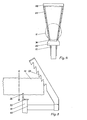
- a frame made of simple parts 11-16 carries a base 21 with an upper support 2 and a base 31 with a lower support 3 in the form of a bracket which on both sides - covered on the opposite side - comprises an inlaid wood H partial iron.
- the upper support 2 consisting of four toothed, inclined, upwardly spread rods, holds the Holt H with those of its teeth which, when the wood is inserted approximately horizontally, corresponds to its thickness, near one end of it from above, the lower support grips it from below, and one saws close to the lower support.
- a tray for the saw is designated, the tray can be pivoted, and a protective plate 5 keeps chips and falling pieces of wood away from the operator, whose location, as can be seen from the inclination of the protective plate and the position of the tray, on the in Fig.l facing away from the sawhorse is intended.
- FIG. 2 shows the upper support 2 used in the example according to FIG. 1, and another embodiment of the lower support, in a view in the direction of the axis of the wood not shown here.
- the lower support is formed here by a pair of small teeth 33 at a short distance from one another and by a pair of larger teeth 34 at a greater distance, so that wood of very different thicknesses is adequately fixed.
- Figure 3 shows a view in the same direction; the top and that lower supports are designed differently here.
- the upper two toothed support rods 25 carry a number of spokes 26 at different heights, the ends of which protrude on both sides are pointed and bent so that their teeth on both sides face the flanks of an inlaid wood, not shown here; the ends are not only downward, but also bent towards the viewer of FIG. 3.
- the lower support is formed by a bracket 32 partially encompassing an inlaid wood, in which a pair of teeth 33 can be provided for securely fixing even very thin billets.
- the reference numbers are only entered on one side of these symmetrical figures.
- the new sawhorse can not only be adapted to a wide variety of wood cross-sectional shapes, but also to a wide variety of tasks.
- Fig. 4 shows in a similar view a greatly simplified embodiment of the new sawing stick; the same is shown in a view from the right in FIG.
- the lower support 35 is limited to grasp the timber H with only one pair of teeth 36 whose mutual distance can then only be a compromise which for Wood is not too small and not too large in diameter, and because only two toothed rods are provided as the upper support, this embodiment is preferably suitable for wood that has grown somewhat roughly, as is the case with the forests in Flatland arises.
- the dash-dotted line AB indicates the plane in which one is sawing (approximately), in the direction from A to B, ie in this direction the saw gap progresses when sawing.
- Fig.5 gives an opportunity to point out that the teeth of the support rods 27 reach less over the end of the wood H, the smaller the tooth pitch (the more teeth you can accommodate on a given rod length), and each less the toothed rods 27 are inclined.
Landscapes
- Life Sciences & Earth Sciences (AREA)
- Engineering & Computer Science (AREA)
- Mechanical Engineering (AREA)
- Wood Science & Technology (AREA)
- Forests & Forestry (AREA)
Applications Claiming Priority (2)
| Application Number | Priority Date | Filing Date | Title |
|---|---|---|---|
| CH264981A CH651777A5 (de) | 1981-04-23 | 1981-04-23 | Vorrichtung zum festhalten zu bearbeitender profilhoelzer. |
| CH2649/81 | 1981-04-23 |
Publications (1)
| Publication Number | Publication Date |
|---|---|
| EP0064480A2 true EP0064480A2 (fr) | 1982-11-10 |
Family
ID=4238491
Family Applications (1)
| Application Number | Title | Priority Date | Filing Date |
|---|---|---|---|
| EP82810170A Withdrawn EP0064480A2 (fr) | 1981-04-23 | 1982-04-23 | Tréteau de sciage |
Country Status (2)
| Country | Link |
|---|---|
| EP (1) | EP0064480A2 (fr) |
| CH (1) | CH651777A5 (fr) |
Cited By (10)
| Publication number | Priority date | Publication date | Assignee | Title |
|---|---|---|---|---|
| WO1984004272A1 (fr) * | 1983-04-27 | 1984-11-08 | Beek Wilhelmus Ch C Van | Chevalet de sciage |
| FR2559416A1 (fr) * | 1983-09-05 | 1985-08-16 | Laligue Guy | Support de sciage a main, a trois pieds stabilisateurs avec guide amovible et reglable |
| EP0206617A3 (fr) * | 1985-06-10 | 1987-06-16 | Arthur J. Hopkins | Porteur de grume |
| GB2187993A (en) * | 1986-03-17 | 1987-09-23 | Joseph Timperon | Log gripper saw bench |
| GB2200319A (en) * | 1987-01-27 | 1988-08-03 | Gordon Kenworthy | Restraint and holding device |
| WO2002034488A1 (fr) * | 2000-10-24 | 2002-05-02 | Charles Errol Brathwaite | Support de travail |
| EP1834743A1 (fr) * | 2006-03-18 | 2007-09-19 | Rudolf Dittrich | Tréteau de sciage de type porte à faux |
| WO2010057176A1 (fr) * | 2008-11-17 | 2010-05-20 | Tie Boss Llc | Dispositif d’attelage de remorque |
| USD658549S1 (en) | 2011-04-27 | 2012-05-01 | Neumann Chad M | Saw buck |
| US9004477B2 (en) | 2011-04-27 | 2015-04-14 | Chad M. Neumann | Saw buck |
-
1981
- 1981-04-23 CH CH264981A patent/CH651777A5/de not_active IP Right Cessation
-
1982
- 1982-04-23 EP EP82810170A patent/EP0064480A2/fr not_active Withdrawn
Cited By (13)
| Publication number | Priority date | Publication date | Assignee | Title |
|---|---|---|---|---|
| WO1984004272A1 (fr) * | 1983-04-27 | 1984-11-08 | Beek Wilhelmus Ch C Van | Chevalet de sciage |
| FR2559416A1 (fr) * | 1983-09-05 | 1985-08-16 | Laligue Guy | Support de sciage a main, a trois pieds stabilisateurs avec guide amovible et reglable |
| EP0206617A3 (fr) * | 1985-06-10 | 1987-06-16 | Arthur J. Hopkins | Porteur de grume |
| GB2187993A (en) * | 1986-03-17 | 1987-09-23 | Joseph Timperon | Log gripper saw bench |
| GB2200319A (en) * | 1987-01-27 | 1988-08-03 | Gordon Kenworthy | Restraint and holding device |
| GB2385556A (en) * | 2000-10-24 | 2003-08-27 | Charles Errol Brathwaite | Work support |
| WO2002034488A1 (fr) * | 2000-10-24 | 2002-05-02 | Charles Errol Brathwaite | Support de travail |
| GB2385556B (en) * | 2000-10-24 | 2005-01-12 | Charles Errol Brathwaite | Work support |
| EP1834743A1 (fr) * | 2006-03-18 | 2007-09-19 | Rudolf Dittrich | Tréteau de sciage de type porte à faux |
| WO2010057176A1 (fr) * | 2008-11-17 | 2010-05-20 | Tie Boss Llc | Dispositif d’attelage de remorque |
| US8616540B2 (en) | 2008-11-17 | 2013-12-31 | Tie Boss Llc | Trailer hitch attachment |
| USD658549S1 (en) | 2011-04-27 | 2012-05-01 | Neumann Chad M | Saw buck |
| US9004477B2 (en) | 2011-04-27 | 2015-04-14 | Chad M. Neumann | Saw buck |
Also Published As
| Publication number | Publication date |
|---|---|
| CH651777A5 (de) | 1985-10-15 |
Similar Documents
| Publication | Publication Date | Title |
|---|---|---|
| EP0064480A2 (fr) | Tréteau de sciage | |
| DE913955C (de) | Kette fuer Motorkettensaege | |
| DE69928526T2 (de) | Vorrichtung zum halten von holzstücken | |
| DE2847353C2 (de) | Maschine zum Abfräsen des Wurzelansatzes von Baumstämmen | |
| DE1956462A1 (de) | Vorrichtung zum gleichzeitigen Behandeln von mehreren gefaellten Baeumen | |
| DE102007039289B4 (de) | Vorrichtung zum Spalten von abgelängten Holzstämmen o. dgl. | |
| AT514697A4 (de) | Vorrichtung zum Schneiden von länglichem Holz | |
| DE3013375C2 (de) | Vorrichtung zum Zerkleinern von Holz | |
| DE3120897A1 (de) | "presse zum herstellen von holmen oder platten aus verleimten staeben" | |
| DE112005000608T5 (de) | Verfahren und Anlage zum Sägen eines unbearbeiteten Baumstammes | |
| DE2552840A1 (de) | Zerspanmaschine | |
| AT528572B1 (de) | Vorrichtung zum Spalten von Holz | |
| DE1199966B (de) | Holzentrindungsmaschine | |
| DE69100462T2 (de) | Vorrichtung und Verfahren zum Spatten von Holz zur Herstellung von Fassdauben. | |
| DE4041704C2 (de) | Verfahren und Vorrichtung zur Herstellung von Quadern aus Holz, insbesondere Palettenklötzen | |
| DE3325923C2 (de) | Vorrichtung zum Zerkleinern von Holz | |
| DE3429212A1 (de) | Als saegebock ausgebildete saegevorrichtung | |
| CH617383A5 (en) | Board-cutting saw with upright frame having bearing rollers mounted in a vertically adjustable manner on a bottom cross member | |
| AT410419B (de) | Brennholzabläng-spaltmaschine | |
| DE2925401C2 (de) | Stichsäge mit Motorantrieb | |
| DE2629764C3 (de) | Vorrichtung zum Wenden der Seitenwarenbretter | |
| AT503076B1 (de) | Holzspaltvorrichtung | |
| DE1453163A1 (de) | Verfahren und Vorrichtung fuer die wirtschaftliche Verwendung des Abfalles beim Holzsaegen | |
| DE2734707A1 (de) | Buendelvorrichtung fuer stabstahl | |
| DE226256C (fr) |
Legal Events
| Date | Code | Title | Description |
|---|---|---|---|
| PUAI | Public reference made under article 153(3) epc to a published international application that has entered the european phase |
Free format text: ORIGINAL CODE: 0009012 |
|
| AK | Designated contracting states |
Designated state(s): AT BE CH DE FR GB SE |
|
| 17P | Request for examination filed |
Effective date: 19830509 |
|
| STAA | Information on the status of an ep patent application or granted ep patent |
Free format text: STATUS: THE APPLICATION IS DEEMED TO BE WITHDRAWN |
|
| 18D | Application deemed to be withdrawn |
Effective date: 19841101 |