EP0064567B1 - Chariot chargeur à panneau rabattable hydrauliquement - Google Patents
Chariot chargeur à panneau rabattable hydrauliquement Download PDFInfo
- Publication number
- EP0064567B1 EP0064567B1 EP81103544A EP81103544A EP0064567B1 EP 0064567 B1 EP0064567 B1 EP 0064567B1 EP 81103544 A EP81103544 A EP 81103544A EP 81103544 A EP81103544 A EP 81103544A EP 0064567 B1 EP0064567 B1 EP 0064567B1
- Authority
- EP
- European Patent Office
- Prior art keywords
- rear wall
- lever
- driver
- frame
- pressure cylinder
- Prior art date
- Legal status (The legal status is an assumption and is not a legal conclusion. Google has not performed a legal analysis and makes no representation as to the accuracy of the status listed.)
- Expired
Links
- 230000007246 mechanism Effects 0.000 claims abstract description 13
- 230000009471 action Effects 0.000 claims description 5
- 239000004459 forage Substances 0.000 description 17
- 230000007935 neutral effect Effects 0.000 description 3
- 230000000087 stabilizing effect Effects 0.000 description 3
- 238000000034 method Methods 0.000 description 2
- 230000008569 process Effects 0.000 description 2
- 230000008901 benefit Effects 0.000 description 1
- 230000008859 change Effects 0.000 description 1
- 238000010276 construction Methods 0.000 description 1
- 230000001627 detrimental effect Effects 0.000 description 1
- 238000010586 diagram Methods 0.000 description 1
- 230000000694 effects Effects 0.000 description 1
- 239000012530 fluid Substances 0.000 description 1
- 230000005484 gravity Effects 0.000 description 1
- 230000002028 premature Effects 0.000 description 1
- 230000000284 resting effect Effects 0.000 description 1
- 230000002441 reversible effect Effects 0.000 description 1
- 238000005096 rolling process Methods 0.000 description 1
- 210000002023 somite Anatomy 0.000 description 1
Images


Classifications
-
- B—PERFORMING OPERATIONS; TRANSPORTING
- B60—VEHICLES IN GENERAL
- B60P—VEHICLES ADAPTED FOR LOAD TRANSPORTATION OR TO TRANSPORT, TO CARRY, OR TO COMPRISE SPECIAL LOADS OR OBJECTS
- B60P1/00—Vehicles predominantly for transporting loads and modified to facilitate loading, consolidating the load, or unloading
- B60P1/04—Vehicles predominantly for transporting loads and modified to facilitate loading, consolidating the load, or unloading with a tipping movement of load-transporting element
- B60P1/26—Means for controlling movement of tailboards or sideboards
-
- A—HUMAN NECESSITIES
- A01—AGRICULTURE; FORESTRY; ANIMAL HUSBANDRY; HUNTING; TRAPPING; FISHING
- A01D—HARVESTING; MOWING
- A01D90/00—Vehicles for carrying harvested crops with means for selfloading or unloading
- A01D90/10—Unloading means
Definitions
- the invention relates to a loading wagon with a rolling or scraper floor, a height-adjustable structure arranged above a fixed structure, and a rear wall which can be pivoted out at the unloading end by means of at least one pressure cylinder articulated on one side on the fixed structure via a lifting mechanism and which has an axis of rotation at the free end of a fixed structure
- pivotally hinged bracket which occupies an approximately horizontal position in its lowest position, is pivotally hinged and can be locked to the fixed structure via at least one spring-loaded latch.
- a rear wall is freely pivoted on a pivotable lever arm.
- the swiveling out of the rear wall is also carried out here by means of a hydraulic cylinder, the hydraulic cylinder swiveling the pivoting lever arm upwards by means of a cable pull and thus pulling up the rear wall hinged to the lever arm.
- a spring-loaded latch is raised on the first swivel path of the hydraulic cylinder, allowing the rear wall to swing backwards.
- the balanced position is the position for «unloading green fodder».
- a disadvantage of the arrangement mentioned is the cumbersome re-engagement of the rear wall, and several braking maneuvers may be required until the rear wall comes back into the locking position. When braking from a higher speed, it can be securely engaged, but the resulting blows on the locking device are detrimental to the service life of these elements, and damage is not excluded. Due to the not very wide swinging out of the rear wall in “green fodder unloading position”, the transverse frame part of the rear wall can cause disabilities. When the lever is pivoted to reach the dry forage unloading position, the rear wall swivels back into its starting position as a result of the change in its center of gravity with respect to its pivot axis until it comes to rest on the lever. Unwindered unloading is not possible by swiveling back the rear wall, since part of the required unloading area is covered by the rear wall.
- an embodiment is known from DE-U-6601 710, wherein a rear wall which can be folded up by means of a hydraulic cylinder is used.
- the loading wagon has a structure for dry forage or for hay, but it is not designed to be foldable.
- the load being loaded up to the upper edge of the fixed side walls, one cannot do without a foldable or removable dry forage construction, which is not required here.
- the invention is based on the object of avoiding the disadvantages mentioned and of designing a rear wall which can be operated from the tractor seat in such a way that problem-free unloading of green fodder in low-sized stables is made possible and unhindered passage during unloading of dry fodder is ensured.
- a lifting mechanism of the swing-out rear wall is formed from a lever which is rotatably mounted at a radial distance from the pivot axis of the rear wall, the free end of which is acted upon by the pressure cylinder articulated on the fixed structure and a driver which moves into the
- the rear wall can be pivoted, has an unlocking device that is articulated on the lever and leads to the bolt, and a further driver that can be brought into the pivoting region of the bracket.
- switching elements in the lifting mechanism, which control elements in the circuit, via which a directional valve is actuated, which controls a pressure cylinder for lifting the rear wall.
- the incremental lifting of the rear wall or bracket has the advantage that only a part of the rear closing wall has to be raised when loading green forage, which means that the energy required for lifting is reduced to a minimum, in contrast to one-piece closing walls.
- Figure 1 shows a partial view of a loading wagon.
- Fixed side walls A are attached above a scraper floor, not shown.
- a foldable structure B is articulated in the upper region of the fixed side walls A.
- an approximately horizontally oriented bracket 1 is articulated in the axis of rotation 1a, which has a pivot axis 2a in which a rear wall 2 is pivotably mounted.
- the rear wall 2 assumes an approximately vertical locking position in the position shown.
- the rear wall 2 is locked to the fixed structure A via a bolt 4 which overlaps a bolt 9 attached to the fixed structure and is pivotably mounted on the rear wall 2 about the axis 4a.
- the cable is in this case on a bolt 14 of the lever 3 attached, to which a tension spring 8 also engages, which is articulated on the rear wall 2.
- the tension spring 8 results in a force which pushes the lever 3 forward.
- a single-acting hydraulic cylinder 5 is articulated on the fixed structure A via the axis 5a and on the lever 3 via the axis 5b.
- the lever 3 has a driver 10 which can be guided into the swivel range of the bracket 1.
- the lever in the area of the axis 5b of the hydraulic cylinder has a driver 11 which projects into the pivoting area of the rear wall 2.
- a tension spring 7 is attached, which is directed against the line of action "W" of the hydraulic cylinder 5.
- the broken line of the bolt 4 in FIG. 1 shows it in the locked position, the hydraulic cylinder being in its retracted position and the driver 11 not yet resting against the rear wall 2.
- a backpack-like mesh covering D is attached between the rear part of the bracket 1 and the rear wall 2.
- Ropes C are tensioned from the outer boundary of the free leg of the bracket 1 and over the highest point of the foldable structure B, which are an upper flexible boundary of the loading space for dry forage.
- the back wall is 2 until the discharge for green forage raised, the driver 1o rests on the bracket 1.
- the bracket 1 together with the rear wall 2 is now raised to an upper position, as shown in FIG. 3, in which the free passage for unloading dry forage, which is generally up to the upper limit of a folding structure B is loaded is guaranteed.
- the outer limit of the free legs of the rear wall 2 and the bracket 1 are approximately at the level of the upper limit of the folding structure B.
- the locking and lifting mechanism can also be attached to the loading wagon on both sides.
- FIG. 4 shows a rear view according to FIG. 1 of the loading wagon rear wall, in which the lifting mechanism is arranged on one side and the tension spring 7 is arranged on both sides.
- the rear wall 2 is in the locked position; the chassis and the folding structure were not shown.
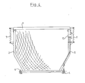
- FIG. 5 shows the function control of the lifting mechanism.
- the lever 3 is assigned two limit switches g and d, which can have an interrupting effect on the circuit when the green forage or dry forage discharge position (FIGS. 2 and 3) is reached.
- the single-acting hydraulic cylinder 5 is controlled starting from a hydraulic pump 15 via a 3/3 way valve and a throttle valve 17. The oil flow is thus throttled in the flow as well as in the return in order to avoid raising and lowering too quickly.
- the directional control valve 16 is shown in its neutral position held by the springs F1 and F2, in which the filling state of the hydraulic cylinder is maintained and thus the lifting height of the rear wall is fixed, i. H. any intermediate position of the rear wall can be set.
- Two electromagnetic valve switches 18 and 19 are connected to ground and each have a feed line 20 or 20, 22 and 21. Depending on which of the two feed lines is connected to potential, the directional control valve takes the position "lifting" or. «Lower».
- connection of the valve switch 18 to the power source is now via the switch g actuated by the lever 3 and the manual switch 23 or the switch d actuated by the lever 3 and the manual switch 23, while the connection of the valve switch 19 to the power source is only via the manual switch 23 .
- the hand switch 23 has an ineffective switching position "0", which is locked, as well as further locked positions "G” and “D” in which the lifting contact is connected to the feed line 24, and finally a keyed switching position S in which the lowering contact via the Supply line 24 is connected to the power source.
- the electrohydraulic control works as follows:
- the electromagnet 18 is activated via the closed switch g.
- the directional control valve 16 is shifted to “H” equal to lifting, with which the hydraulic cylinder is pressurized with hydraulic fluid via the hydraulic line 12 and extends.
- the lever 3 is pivoted thereby, with which the lifting process of the rear wall 2, which has already been described, is carried out until the unloading position for green fodder is reached.
- the switch "g" is actuated by the lever 3, which opens it and thus interrupts the power supply to the electromagnet 18.
- the directional valve is returned to the neutral position "N" by the spring F2, whereby the supply of pressure medium to the hydraulic cylinder is interrupted. The return of pressure medium from the hydraulic cylinder is blocked, so that the hydraulic cylinder or the rear wall remains in this position.
- the hand switch 23 is set to " S " equal to lower. There is an action on the electromagnet 19, which shifts the directional control valve 16 to sinks S, which results in the backflow of the pressure medium and the back wall 2 returns due to its own weight under the action of the springs 7 in its locking position.
- the lever 3 is also pivoted back again, so that the switch "g" returns to its closed position and a new "lift command” can thus be carried out.
- any intermediate position of the rear wall or bracket can be set with this control.
Landscapes
- Engineering & Computer Science (AREA)
- Life Sciences & Earth Sciences (AREA)
- Environmental Sciences (AREA)
- Transportation (AREA)
- Mechanical Engineering (AREA)
- Agricultural Machines (AREA)
- Shovels (AREA)
- Types And Forms Of Lifts (AREA)
Claims (9)
Priority Applications (3)
| Application Number | Priority Date | Filing Date | Title |
|---|---|---|---|
| AT81103544T ATE8318T1 (de) | 1981-05-09 | 1981-05-09 | Ladewagen mit hydraulisch verschwenkbarer rueckwand. |
| DE8181103544T DE3164698D1 (en) | 1981-05-09 | 1981-05-09 | Car loader with hydraulically tiltable tailboard |
| EP81103544A EP0064567B1 (fr) | 1981-05-09 | 1981-05-09 | Chariot chargeur à panneau rabattable hydrauliquement |
Applications Claiming Priority (1)
| Application Number | Priority Date | Filing Date | Title |
|---|---|---|---|
| EP81103544A EP0064567B1 (fr) | 1981-05-09 | 1981-05-09 | Chariot chargeur à panneau rabattable hydrauliquement |
Publications (2)
| Publication Number | Publication Date |
|---|---|
| EP0064567A1 EP0064567A1 (fr) | 1982-11-17 |
| EP0064567B1 true EP0064567B1 (fr) | 1984-07-11 |
Family
ID=8187706
Family Applications (1)
| Application Number | Title | Priority Date | Filing Date |
|---|---|---|---|
| EP81103544A Expired EP0064567B1 (fr) | 1981-05-09 | 1981-05-09 | Chariot chargeur à panneau rabattable hydrauliquement |
Country Status (3)
| Country | Link |
|---|---|
| EP (1) | EP0064567B1 (fr) |
| AT (1) | ATE8318T1 (fr) |
| DE (1) | DE3164698D1 (fr) |
Families Citing this family (6)
| Publication number | Priority date | Publication date | Assignee | Title |
|---|---|---|---|---|
| GB2233938B (en) * | 1989-07-21 | 1993-10-27 | Glyndwr Shaw | Improvements in or relating to vehicle tail-gate latching mechanisms. |
| DE4205046A1 (de) * | 1992-02-19 | 1993-08-26 | Scheibenzuber Jun Josef | Schliessmechanismus |
| AT401135B (de) * | 1994-05-10 | 1996-06-25 | Bauer & Co Gmbh Reform Werke | An einem ladewagen für halm- und/oder blattgut vorgesehene entlade- und dosiereinrichtung für das entladegut |
| DE29510800U1 (de) * | 1995-07-04 | 1996-10-31 | Maschinenfabrik Kemper GmbH, 48703 Stadtlohn | Ladewagen zur Beförderung von insbesondere Erntegut |
| FR2755075B1 (fr) * | 1996-10-24 | 1998-12-04 | Bricaud Jean Paul | Benne du type a vidage par basculement |
| DE202022103972U1 (de) | 2022-07-14 | 2023-10-17 | Pöttinger Landtechnik Gmbh | Landwirtschaftlicher Ladewagen |
Family Cites Families (3)
| Publication number | Priority date | Publication date | Assignee | Title |
|---|---|---|---|---|
| DE6601710U (de) * | 1967-12-02 | 1969-03-20 | Landmaschinenfabrik B Strautma | Antrag auf erteilung eines hilfsgebrauchsmusters |
| DE6929397U (de) * | 1969-07-23 | 1970-01-08 | Fahr A G Gottmadingen Maschf | Hydraulische entriegenungsvorrichtung und entriegelungsvorrichtung einer rueckwand eines gezogenen oder selbstfahrenden ladewagens |
| DE2019055A1 (de) * | 1970-04-21 | 1971-11-11 | Gruber, Otto, Saalfelden (Österreich) | Landwirtschaftlicher Ladewagen |
-
1981
- 1981-05-09 DE DE8181103544T patent/DE3164698D1/de not_active Expired
- 1981-05-09 AT AT81103544T patent/ATE8318T1/de not_active IP Right Cessation
- 1981-05-09 EP EP81103544A patent/EP0064567B1/fr not_active Expired
Also Published As
| Publication number | Publication date |
|---|---|
| ATE8318T1 (de) | 1984-07-15 |
| DE3164698D1 (en) | 1984-08-16 |
| EP0064567A1 (fr) | 1982-11-17 |
Similar Documents
| Publication | Publication Date | Title |
|---|---|---|
| DE19705010B4 (de) | Fahrzeugsitz-Aufhängungssystem | |
| CH630567A5 (de) | Ladevorrichtung fuer lastfahrzeugaufbauten. | |
| DE1556560B1 (de) | Schiffsladevorrichtung | |
| EP0064567B1 (fr) | Chariot chargeur à panneau rabattable hydrauliquement | |
| DE3685681T2 (de) | Lasthebevorrichtung. | |
| EP1055360A1 (fr) | Dispositif de coupe avec fixation non-bloquante du rabatteur | |
| DE69612518T2 (de) | Mähmaschine mit einer Betätigungsvorrichtung einer Entlastungsfeder des Mähmechanismus | |
| DD208958A5 (de) | Vorrichtung zur parallelachsigen kinematischen steuerung eines hebemaschinen-auslegers | |
| DE1634764A1 (de) | Vorrichtung zum Verschwenken eines an ein Tragfahrzeug schwenkbar angeschlossenen,eventuell mit einem Bedienungssitz versehenen Tiefloeffels | |
| DE1781267C3 (de) | Hydraulische Steuervorrichtung für einen an einem Schlepper angeordneten Schaufellader | |
| DE10063610B4 (de) | Steuereinrichtung zur Steuerung einer hydraulischen Schwenkantriebsvorrichtung | |
| DE69012018T2 (de) | Öffnungs- und Verschlussvorrichtung für die Hintertür eines Anhängers. | |
| DE1932040A1 (de) | Gewichtsuebertragungskupplung | |
| DE2627535C3 (de) | Beladerohr für Schüttgut | |
| DE69205374T2 (de) | Verbesserungen an hydraulischen Aufhängungen von Lastkraftwagen. | |
| DE1482916B2 (de) | Maehmaschine mit einem maehtisch | |
| DE4016789A1 (de) | Vorrichtung an einer ladebordwand | |
| DE4004960A1 (de) | Vorrichtung an einer ladebordwand | |
| DE29803468U1 (de) | Korntank für ein Getreide-Erntefahrzeug | |
| DE2436457A1 (de) | Hydraulische steuervorrichtung fuer die ausheb- und absenkbewegungen eines mit mehreren pflugscharen versehenen pfluges | |
| DE69514879T2 (de) | Serviceeinrichtung an Arbeitsfahrzeugen | |
| DE9317545U1 (de) | Schwenkbare Bordwand eines Transportfahrzeugs | |
| DE1949438U (de) | Steuervorrichtung fuer ein hydraulisch verschwenkbares ankoppelungsgestaenge fuer ein landwirtschaftliches geraet an einem schlepper. | |
| DE3838424A1 (de) | Frontlenker-zugmaschine mit kippbarem fahrerhaus | |
| CH328999A (de) | Liegemöbel mit verstellbarem Teil |
Legal Events
| Date | Code | Title | Description |
|---|---|---|---|
| PUAI | Public reference made under article 153(3) epc to a published international application that has entered the european phase |
Free format text: ORIGINAL CODE: 0009012 |
|
| AK | Designated contracting states |
Designated state(s): AT CH DE FR GB IT NL |
|
| 17P | Request for examination filed |
Effective date: 19821203 |
|
| ITF | It: translation for a ep patent filed | ||
| GRAA | (expected) grant |
Free format text: ORIGINAL CODE: 0009210 |
|
| AK | Designated contracting states |
Designated state(s): AT CH DE FR GB IT LI NL |
|
| REF | Corresponds to: |
Ref document number: 8318 Country of ref document: AT Date of ref document: 19840715 Kind code of ref document: T |
|
| REF | Corresponds to: |
Ref document number: 3164698 Country of ref document: DE Date of ref document: 19840816 |
|
| ET | Fr: translation filed | ||
| PLBE | No opposition filed within time limit |
Free format text: ORIGINAL CODE: 0009261 |
|
| STAA | Information on the status of an ep patent application or granted ep patent |
Free format text: STATUS: NO OPPOSITION FILED WITHIN TIME LIMIT |
|
| 26N | No opposition filed | ||
| PG25 | Lapsed in a contracting state [announced via postgrant information from national office to epo] |
Ref country code: FR Free format text: LAPSE BECAUSE OF NON-PAYMENT OF DUE FEES Effective date: 19880129 |
|
| GBPC | Gb: european patent ceased through non-payment of renewal fee | ||
| REG | Reference to a national code |
Ref country code: FR Ref legal event code: ST |
|
| PG25 | Lapsed in a contracting state [announced via postgrant information from national office to epo] |
Ref country code: GB Free format text: LAPSE BECAUSE OF NON-PAYMENT OF DUE FEES Effective date: 19881121 |
|
| REG | Reference to a national code |
Ref country code: CH Ref legal event code: PUE Owner name: GREENLAND GMBH & CO. KG |
|
| NLS | Nl: assignments of ep-patents |
Owner name: GREENLAND GMBH & CO. KG TE GOTTMADINGEN, BONDSREPU |
|
| PGFP | Annual fee paid to national office [announced via postgrant information from national office to epo] |
Ref country code: CH Payment date: 19950418 Year of fee payment: 15 |
|
| PGFP | Annual fee paid to national office [announced via postgrant information from national office to epo] |
Ref country code: AT Payment date: 19950426 Year of fee payment: 15 |
|
| PGFP | Annual fee paid to national office [announced via postgrant information from national office to epo] |
Ref country code: NL Payment date: 19950531 Year of fee payment: 15 |
|
| PGFP | Annual fee paid to national office [announced via postgrant information from national office to epo] |
Ref country code: DE Payment date: 19950630 Year of fee payment: 15 |
|
| PG25 | Lapsed in a contracting state [announced via postgrant information from national office to epo] |
Ref country code: AT Effective date: 19960509 |
|
| PG25 | Lapsed in a contracting state [announced via postgrant information from national office to epo] |
Ref country code: LI Effective date: 19960531 Ref country code: CH Effective date: 19960531 |
|
| PG25 | Lapsed in a contracting state [announced via postgrant information from national office to epo] |
Ref country code: NL Effective date: 19961201 |
|
| REG | Reference to a national code |
Ref country code: CH Ref legal event code: PL |
|
| PG25 | Lapsed in a contracting state [announced via postgrant information from national office to epo] |
Ref country code: DE Effective date: 19970201 |
|
| NLV4 | Nl: lapsed or anulled due to non-payment of the annual fee |
Effective date: 19961201 |