EP0064598A1 - Segment pour un palier hydrodynamique - Google Patents
Segment pour un palier hydrodynamique Download PDFInfo
- Publication number
- EP0064598A1 EP0064598A1 EP82102838A EP82102838A EP0064598A1 EP 0064598 A1 EP0064598 A1 EP 0064598A1 EP 82102838 A EP82102838 A EP 82102838A EP 82102838 A EP82102838 A EP 82102838A EP 0064598 A1 EP0064598 A1 EP 0064598A1
- Authority
- EP
- European Patent Office
- Prior art keywords
- bearing
- transverse groove
- segment
- hydrodynamic
- rotating element
- Prior art date
- Legal status (The legal status is an assumption and is not a legal conclusion. Google has not performed a legal analysis and makes no representation as to the accuracy of the status listed.)
- Granted
Links
- 230000001050 lubricating effect Effects 0.000 claims abstract description 8
- 239000010687 lubricating oil Substances 0.000 claims abstract description 8
- 239000003921 oil Substances 0.000 description 16
- 230000002706 hydrostatic effect Effects 0.000 description 4
- 238000012544 monitoring process Methods 0.000 description 2
- 230000003068 static effect Effects 0.000 description 2
- 238000010276 construction Methods 0.000 description 1
- 238000001816 cooling Methods 0.000 description 1
- 238000003754 machining Methods 0.000 description 1
- 238000000034 method Methods 0.000 description 1
- 210000000056 organ Anatomy 0.000 description 1
- 230000010355 oscillation Effects 0.000 description 1
- 239000011435 rock Substances 0.000 description 1
Images

Classifications
-
- F—MECHANICAL ENGINEERING; LIGHTING; HEATING; WEAPONS; BLASTING
- F16—ENGINEERING ELEMENTS AND UNITS; GENERAL MEASURES FOR PRODUCING AND MAINTAINING EFFECTIVE FUNCTIONING OF MACHINES OR INSTALLATIONS; THERMAL INSULATION IN GENERAL
- F16C—SHAFTS; FLEXIBLE SHAFTS; ELEMENTS OR CRANKSHAFT MECHANISMS; ROTARY BODIES OTHER THAN GEARING ELEMENTS; BEARINGS
- F16C17/00—Sliding-contact bearings for exclusively rotary movement
- F16C17/02—Sliding-contact bearings for exclusively rotary movement for radial load only
- F16C17/03—Sliding-contact bearings for exclusively rotary movement for radial load only with tiltably-supported segments, e.g. Michell bearings
-
- F—MECHANICAL ENGINEERING; LIGHTING; HEATING; WEAPONS; BLASTING
- F16—ENGINEERING ELEMENTS AND UNITS; GENERAL MEASURES FOR PRODUCING AND MAINTAINING EFFECTIVE FUNCTIONING OF MACHINES OR INSTALLATIONS; THERMAL INSULATION IN GENERAL
- F16C—SHAFTS; FLEXIBLE SHAFTS; ELEMENTS OR CRANKSHAFT MECHANISMS; ROTARY BODIES OTHER THAN GEARING ELEMENTS; BEARINGS
- F16C33/00—Parts of bearings; Special methods for making bearings or parts thereof
- F16C33/02—Parts of sliding-contact bearings
- F16C33/04—Brasses; Bushes; Linings
- F16C33/06—Sliding surface mainly made of metal
- F16C33/10—Construction relative to lubrication
Definitions
- the invention relates to a bearing segment for a hydrodynamic radial plain bearing, with a transverse groove provided in the bearing surface on the inlet side of the rotating element and serving for distributing lubricating oil over the axial bearing width and feeding a hydrodynamic lubricating wedge.
- the object of the invention is to create a bearing segment for a hydrodynamic radial slide bearing of the type mentioned at the outset, which is distinguished by a higher mean specific surface load in comparison with known designs and which permits a particularly narrow bearing construction.
- This object is achieved in that two longitudinal grooves are connected to the two ends of the transverse groove serving to distribute the lubricating oil over the axial bearing width via a throttle, which limit the bearing surface in the axial direction.
- FIGS. 1 to 5 illustrate the generally known prior art.
- Fig. 1 shows a plan view of a segment of a hydrodynamic radial plain bearing and Fig. 2 shows a section along the line II of Fig. 1.
- This bearing segment 1 contains in its bearing surface 2 on the inlet side of the (not shown) rotating Elements a transverse groove 3, which is connected to a lubricating oil supply line 4 and is used to distribute the lubricating oil over the axial bearing width.
- This transverse groove 3 feeds the hydrodynamic lubricating wedge in a known manner, which is formed during operation between the bearing surface 2 and the rotating element.
- Fig. 3 illustrates the pressure distribution along the circumference of the bearing segment 1, namely in the section plane II-II (i.e. in the middle of the bearing). 4 and 5 show cross sections through this pressure mountain (along lines IV-IV and V-V of Fig. 3).
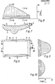
- FIG. 6 shows a plan view of a bearing segment according to the invention
- FIG. 7 shows a section along the line VII-VII of FIG. 6, while FIGS. 8, 9 and 10 show sections through the build-up of pressure along the lines VIII-VIII, IX- Show IX or XX.
- the bearing segment 11 contains in its bearing surface 12 a transverse groove 13 which is connected to a lubricating oil supply line 14.
- the two ends of this transverse groove 13 are each connected via a throttle 15, 16 to longitudinal grooves 17, 18 which extend the bearing surface 12 in the axial direction, i.e. limit near the longitudinal edges 12a, 12b.
- the hydrodynamic lubricating wedge that forms in the gap between the bearing segment 11 and the rotating element during operation is supported as a result on its two flanks (ie in the region of the longitudinal grooves 17, 18) against a higher pressure level than the atmosphere.
- the side flow is significantly reduced and the volume of the pressure mountain is increased approximately by the base which is striped across in FIGS. 8 to 10.
- This increase in the volume of the pressure rock corresponds to a proportional increase in the load capacity of the bearing segment.
- the solution according to the invention thus allows either to increase the bearing capacity of the bearing and / or to make the bearing narrower.
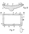
- the bearing segment 31 contains, in addition to the transverse groove 33 provided on the inlet side of the rotating element and the two longitudinal grooves 37, 38 connected via throttles 35, 36, a transverse groove 39 provided on the outlet side of the rotating element, which via throttles 40, 41 is connected to the longitudinal grooves 37, 38.
- the design is expediently such that the throttles 35, 36 bring about a pressure drop of 5 to 30 % , preferably from 10 to 20%, during normal operation, while the throttles 40, 41 cause a pressure drop of 70 to 95%, preferably from 80 to 90 %, cause.
- the transverse groove 39 then represents the oil reservoir from which the hydrodynamic lubricating wedge is fed.
- the connection of this transverse groove 39 to the longitudinal grooves 37, 38 via the throttles 40, 41 ensures that a small oil reservoir is formed in the transverse groove 39 in every spatial position of the bearing segment 31, which causes the bearing to run dry for a limited time when the direction of rotation is changed prevented.
- a hydraulic accumulator 42 is connected to the transverse groove 33 and maintains a certain oil pressure even if the main oil supply fails.
- the throttles provided in the position according to the invention as a connection between the transverse groove and the two longitudinal grooves form safety organs which, in the case of unfavorable gap conditions, prevent an uncontrolled outflow of the lubricating oil via the two longitudinal grooves. It should be noted that, especially with large dimensions of the rotating element (e.g. when storing large tube mills), ideal gap conditions can by no means always be expected, but that machining tolerances, mechanical deformations and temperature-related deformations must be taken into account.
- the feed pressure in the transverse groove on the inlet side of the rotating element should be between 3 and 30 bar for large bearing segments, such as are used for the storage of tube mills, drums and the like.
- the throttles leading to the longitudinal grooves are dimensioned such that the pressure loss occurring therein is preferably between 10 and 20%.
- a further advantage is that the starting aid usually used in hydrodynamic bearings can be dispensed with (such starting aid for large hydrodynamic bearings usually consists of a central bore in the bearing segment through which the high-pressure oil turns before being rotated metallic contact between the pin and the bearing is removed).
Landscapes
- Engineering & Computer Science (AREA)
- General Engineering & Computer Science (AREA)
- Mechanical Engineering (AREA)
- Physics & Mathematics (AREA)
- Fluid Mechanics (AREA)
- Sliding-Contact Bearings (AREA)
- Magnetic Bearings And Hydrostatic Bearings (AREA)
Priority Applications (1)
| Application Number | Priority Date | Filing Date | Title |
|---|---|---|---|
| AT82102838T ATE11328T1 (de) | 1981-05-05 | 1982-04-02 | Lagersegment fuer ein hydrodynamisches gleitlager. |
Applications Claiming Priority (2)
| Application Number | Priority Date | Filing Date | Title |
|---|---|---|---|
| DE3117746 | 1981-05-05 | ||
| DE19813117746 DE3117746A1 (de) | 1981-05-05 | 1981-05-05 | Hydrodynamisches radial-gleitlager |
Publications (2)
| Publication Number | Publication Date |
|---|---|
| EP0064598A1 true EP0064598A1 (fr) | 1982-11-17 |
| EP0064598B1 EP0064598B1 (fr) | 1985-01-16 |
Family
ID=6131493
Family Applications (1)
| Application Number | Title | Priority Date | Filing Date |
|---|---|---|---|
| EP82102838A Expired EP0064598B1 (fr) | 1981-05-05 | 1982-04-02 | Segment pour un palier hydrodynamique |
Country Status (7)
| Country | Link |
|---|---|
| EP (1) | EP0064598B1 (fr) |
| AT (1) | ATE11328T1 (fr) |
| BR (1) | BR8202572A (fr) |
| CA (1) | CA1186358A (fr) |
| DE (2) | DE3117746A1 (fr) |
| ES (1) | ES277883Y (fr) |
| ZA (1) | ZA822102B (fr) |
Cited By (6)
| Publication number | Priority date | Publication date | Assignee | Title |
|---|---|---|---|---|
| GB2256681A (en) * | 1991-02-25 | 1992-12-16 | Metal Leve Sa | A bearing for an internal combustion engine. |
| US5290899A (en) * | 1988-09-22 | 1994-03-01 | Tosoh Corporation | Photosensitive material having a silicon-containing polymer |
| EP1722116A1 (fr) * | 2005-05-11 | 2006-11-15 | Carl Freudenberg KG | Palier lisse |
| EP2878837A1 (fr) * | 2013-11-08 | 2015-06-03 | Mitsubishi Hitachi Power Systems, Ltd. | Palier de butée à patins oscillants et machine rotative dotée de celui-ci |
| JP2017502232A (ja) * | 2014-01-24 | 2017-01-19 | マン・ディーゼル・アンド・ターボ・エスイー | 軸受装置のためのティルティングセグメントおよび軸受装置 |
| CN120739800A (zh) * | 2025-07-23 | 2025-10-03 | 东方电气集团东方电机有限公司 | 一种辅助启动的推力轴承瓦、推力轴承及使用方法 |
Families Citing this family (6)
| Publication number | Priority date | Publication date | Assignee | Title |
|---|---|---|---|---|
| SE442328B (sv) * | 1983-09-29 | 1985-12-16 | Jan R Schnittger | Hydrodynamisk lagerenhet |
| IT1395717B1 (it) * | 2009-09-22 | 2012-10-19 | Nuovo Pignone Spa | Cuscinetto, meccanismo di distribuzione olio e metodo. |
| IT1395716B1 (it) | 2009-09-22 | 2012-10-19 | Nuovo Pignone Spa | Cuscinetto, meccanismo di fissaggio e metodo per fissare almeno un pattino. |
| DE102013224117A1 (de) | 2013-11-26 | 2015-05-28 | Sms Siemag Ag | Walzenanordnung für Walzen in einer Walzanlage |
| DE102015209637A1 (de) | 2015-05-26 | 2016-12-01 | Sms Group Gmbh | Walzenanordnung |
| EP4170191A1 (fr) | 2021-10-20 | 2023-04-26 | Flender-Graffenstaden S.A.S. | Palier hydrodynamique, boîte de vitesses et utilisation |
Citations (4)
| Publication number | Priority date | Publication date | Assignee | Title |
|---|---|---|---|---|
| CH274953A (de) * | 1949-07-06 | 1951-04-30 | Sulzer Ag | Gleitlager. |
| US3352610A (en) * | 1965-02-04 | 1967-11-14 | Furukawa Yuichiro | Bearing for impeller shaft |
| DE2147207A1 (de) * | 1970-09-23 | 1972-03-30 | Skf Ind Trading & Dev | Hydrostatisches Lager |
| DE2211414A1 (de) * | 1972-03-06 | 1973-09-13 | Siemens Ag | Hydrodynamisches spurlager mit mittig unterstuetzten kippsegmenten fuer eine in zwei drehrichtungen rotierende welle |
Family Cites Families (4)
| Publication number | Priority date | Publication date | Assignee | Title |
|---|---|---|---|---|
| GB371479A (en) * | 1931-01-28 | 1932-04-28 | James Lawrence Myers | Grooved bearings |
| DE2100365B2 (de) * | 1971-01-07 | 1981-09-17 | Ekkehard Dr.-Ing. 7100 Heilbronn Grau | Gleitlager mit Schmiernutensystem |
| FR2229287A5 (en) * | 1973-05-11 | 1974-12-06 | Worthington France | Rotary fluid press. generating device - has shaft rotating about axis eccentric w.r.t. axis of cylinder |
| DE2931383A1 (de) * | 1979-08-02 | 1981-02-19 | Polysius Ag | Hydrodynamisches lager |
-
1981
- 1981-05-05 DE DE19813117746 patent/DE3117746A1/de not_active Withdrawn
-
1982
- 1982-03-25 CA CA000399441A patent/CA1186358A/fr not_active Expired
- 1982-03-29 ZA ZA822102A patent/ZA822102B/xx unknown
- 1982-04-02 DE DE8282102838T patent/DE3261910D1/de not_active Expired
- 1982-04-02 AT AT82102838T patent/ATE11328T1/de not_active IP Right Cessation
- 1982-04-02 EP EP82102838A patent/EP0064598B1/fr not_active Expired
- 1982-05-04 BR BR8202572A patent/BR8202572A/pt unknown
- 1982-05-04 ES ES1982277883U patent/ES277883Y/es not_active Expired
Patent Citations (4)
| Publication number | Priority date | Publication date | Assignee | Title |
|---|---|---|---|---|
| CH274953A (de) * | 1949-07-06 | 1951-04-30 | Sulzer Ag | Gleitlager. |
| US3352610A (en) * | 1965-02-04 | 1967-11-14 | Furukawa Yuichiro | Bearing for impeller shaft |
| DE2147207A1 (de) * | 1970-09-23 | 1972-03-30 | Skf Ind Trading & Dev | Hydrostatisches Lager |
| DE2211414A1 (de) * | 1972-03-06 | 1973-09-13 | Siemens Ag | Hydrodynamisches spurlager mit mittig unterstuetzten kippsegmenten fuer eine in zwei drehrichtungen rotierende welle |
Non-Patent Citations (1)
| Title |
|---|
| VDI-BERICHTE, Nr. 111, 1966, Düsseldorf, K. DROSTE: "Schmierungsgerechte Konstruktion" Seiten 15 bis 19 * |
Cited By (10)
| Publication number | Priority date | Publication date | Assignee | Title |
|---|---|---|---|---|
| US5290899A (en) * | 1988-09-22 | 1994-03-01 | Tosoh Corporation | Photosensitive material having a silicon-containing polymer |
| GB2256681A (en) * | 1991-02-25 | 1992-12-16 | Metal Leve Sa | A bearing for an internal combustion engine. |
| GB2256681B (en) * | 1991-02-25 | 1995-09-06 | Metal Leve Sa | A bearing for an internal combustion engine |
| EP1722116A1 (fr) * | 2005-05-11 | 2006-11-15 | Carl Freudenberg KG | Palier lisse |
| EP2878837A1 (fr) * | 2013-11-08 | 2015-06-03 | Mitsubishi Hitachi Power Systems, Ltd. | Palier de butée à patins oscillants et machine rotative dotée de celui-ci |
| US9670957B2 (en) | 2013-11-08 | 2017-06-06 | Mitsubishi Hitachi Power Systems, Ltd. | Tilting-pad thrust bearing and rotary machine having the same |
| JP2017502232A (ja) * | 2014-01-24 | 2017-01-19 | マン・ディーゼル・アンド・ターボ・エスイー | 軸受装置のためのティルティングセグメントおよび軸受装置 |
| EP3097316B1 (fr) * | 2014-01-24 | 2019-06-05 | MAN Energy Solutions SE | Patin oscillant pour dispositif formant palier d'arbre et dispositif formant palier d'arbre |
| US10408258B2 (en) | 2014-01-24 | 2019-09-10 | Man Energy Solutions Se | Tilting segment for a shaft bearing device, and shaft bearing device |
| CN120739800A (zh) * | 2025-07-23 | 2025-10-03 | 东方电气集团东方电机有限公司 | 一种辅助启动的推力轴承瓦、推力轴承及使用方法 |
Also Published As
| Publication number | Publication date |
|---|---|
| EP0064598B1 (fr) | 1985-01-16 |
| BR8202572A (pt) | 1983-04-19 |
| ATE11328T1 (de) | 1985-02-15 |
| DE3261910D1 (en) | 1985-02-28 |
| DE3117746A1 (de) | 1982-12-09 |
| CA1186358A (fr) | 1985-04-30 |
| ES277883Y (es) | 1985-06-16 |
| ZA822102B (en) | 1983-03-30 |
| ES277883U (es) | 1984-12-16 |
Similar Documents
| Publication | Publication Date | Title |
|---|---|---|
| DE69007079T2 (de) | Buchse für Ölfilmlager. | |
| EP0064598B1 (fr) | Segment pour un palier hydrodynamique | |
| DE2843658A1 (de) | Oelfilmlager | |
| EP0753678B1 (fr) | Palier à contact lisse pour un arbre | |
| DE3244893A1 (de) | Axialschublager fuer turbolader | |
| DE3010406A1 (de) | Hydrostatische dichtung fuer zentrifugalpumpen | |
| DE2356817A1 (de) | Eigenversorgtes hydrostatisches lager fuer eine umlaufende welle | |
| DE1525194C2 (de) | Dynamisch geschmiertes Axial - Radialgleitlager | |
| AT390129B (de) | Hydrodynamische gleitlageranordnung fuer drehende lagerzapfen bzw. wellenzapfen | |
| DE2100365B2 (de) | Gleitlager mit Schmiernutensystem | |
| DE2930107A1 (de) | Hochdruckpumpe mit druckregler | |
| DE2118077C3 (de) | Hydrostatisches Radialgleitlager | |
| DE2636252A1 (de) | Arbeitszylinder | |
| DE1775519C3 (de) | Hydrostatisches Axial-Radiallager | |
| EP0105050A1 (fr) | Palier hydrostatique | |
| DE3301353A1 (de) | Lageranordnung fuer ein belastbares maschinenteil | |
| EP0068103B1 (fr) | Palier hydrodynamique | |
| DE102015219752A1 (de) | Lagerbuchse | |
| DE102015209637A1 (de) | Walzenanordnung | |
| DE10030698A1 (de) | Verfahren zum Schmieren und Kühlen eines hydrodynamischen Gleitlagers und Vorrichtung zur Durchführung dieses Verfahrens | |
| DE3522037C2 (fr) | ||
| DE2056071A1 (de) | Hydraulische Nachstellvorrichtung fur Werkzeuge | |
| DE2456032A1 (de) | Regler fuer die druckmittelschmierung eines hydrostatischen lagers | |
| DE1502891A1 (de) | Vorrichtung zur Stabilisierung des Drehtisches einer Werkzeugmaschine | |
| DE3446387A1 (de) | Verfahren und vorrichtung zur schmiermittelzufuehrung |
Legal Events
| Date | Code | Title | Description |
|---|---|---|---|
| PUAI | Public reference made under article 153(3) epc to a published international application that has entered the european phase |
Free format text: ORIGINAL CODE: 0009012 |
|
| AK | Designated contracting states |
Designated state(s): AT BE DE FR GB IT SE |
|
| 17P | Request for examination filed |
Effective date: 19821121 |
|
| ITF | It: translation for a ep patent filed | ||
| GRAA | (expected) grant |
Free format text: ORIGINAL CODE: 0009210 |
|
| AK | Designated contracting states |
Designated state(s): AT BE DE FR GB IT SE |
|
| REF | Corresponds to: |
Ref document number: 11328 Country of ref document: AT Date of ref document: 19850215 Kind code of ref document: T |
|
| REF | Corresponds to: |
Ref document number: 3261910 Country of ref document: DE Date of ref document: 19850228 |
|
| ET | Fr: translation filed | ||
| PGFP | Annual fee paid to national office [announced via postgrant information from national office to epo] |
Ref country code: AT Payment date: 19850311 Year of fee payment: 4 |
|
| PLBE | No opposition filed within time limit |
Free format text: ORIGINAL CODE: 0009261 |
|
| STAA | Information on the status of an ep patent application or granted ep patent |
Free format text: STATUS: NO OPPOSITION FILED WITHIN TIME LIMIT |
|
| 26N | No opposition filed | ||
| PG25 | Lapsed in a contracting state [announced via postgrant information from national office to epo] |
Ref country code: AT Effective date: 19860402 |
|
| PG25 | Lapsed in a contracting state [announced via postgrant information from national office to epo] |
Ref country code: SE Effective date: 19860403 |
|
| PG25 | Lapsed in a contracting state [announced via postgrant information from national office to epo] |
Ref country code: BE Effective date: 19860430 |
|
| BERE | Be: lapsed |
Owner name: KRUPP POLYSIUS A.G. Effective date: 19860430 |
|
| GBPC | Gb: european patent ceased through non-payment of renewal fee | ||
| PG25 | Lapsed in a contracting state [announced via postgrant information from national office to epo] |
Ref country code: FR Free format text: LAPSE BECAUSE OF NON-PAYMENT OF DUE FEES Effective date: 19861231 |
|
| PG25 | Lapsed in a contracting state [announced via postgrant information from national office to epo] |
Ref country code: DE Effective date: 19870101 |
|
| REG | Reference to a national code |
Ref country code: FR Ref legal event code: ST |
|
| PG25 | Lapsed in a contracting state [announced via postgrant information from national office to epo] |
Ref country code: GB Effective date: 19881121 |
|
| EUG | Se: european patent has lapsed |
Ref document number: 82102838.8 Effective date: 19870224 |