EP0064652A2 - Dispositif d'ancrage pour des matériaux composites de filaments - Google Patents
Dispositif d'ancrage pour des matériaux composites de filaments Download PDFInfo
- Publication number
- EP0064652A2 EP0064652A2 EP82103491A EP82103491A EP0064652A2 EP 0064652 A2 EP0064652 A2 EP 0064652A2 EP 82103491 A EP82103491 A EP 82103491A EP 82103491 A EP82103491 A EP 82103491A EP 0064652 A2 EP0064652 A2 EP 0064652A2
- Authority
- EP
- European Patent Office
- Prior art keywords
- rod
- bore
- element according
- fiber composite
- force application
- Prior art date
- Legal status (The legal status is an assumption and is not a legal conclusion. Google has not performed a legal analysis and makes no representation as to the accuracy of the status listed.)
- Granted
Links
Images

Classifications
-
- E—FIXED CONSTRUCTIONS
- E04—BUILDING
- E04C—STRUCTURAL ELEMENTS; BUILDING MATERIALS
- E04C5/00—Reinforcing elements, e.g. for concrete; Auxiliary elements therefor
- E04C5/08—Members specially adapted to be used in prestressed constructions
- E04C5/12—Anchoring devices
- E04C5/125—Anchoring devices the tensile members are profiled to ensure the anchorage, e.g. when provided with screw-thread, bulges, corrugations
-
- F—MECHANICAL ENGINEERING; LIGHTING; HEATING; WEAPONS; BLASTING
- F16—ENGINEERING ELEMENTS AND UNITS; GENERAL MEASURES FOR PRODUCING AND MAINTAINING EFFECTIVE FUNCTIONING OF MACHINES OR INSTALLATIONS; THERMAL INSULATION IN GENERAL
- F16B—DEVICES FOR FASTENING OR SECURING CONSTRUCTIONAL ELEMENTS OR MACHINE PARTS TOGETHER, e.g. NAILS, BOLTS, CIRCLIPS, CLAMPS, CLIPS OR WEDGES; JOINTS OR JOINTING
- F16B13/00—Dowels or other devices fastened in walls or the like by inserting them in holes made therein for that purpose
- F16B13/14—Non-metallic plugs or sleeves; Use of liquid, loose solid or kneadable material therefor
- F16B13/141—Fixing plugs in holes by the use of settable material
-
- F—MECHANICAL ENGINEERING; LIGHTING; HEATING; WEAPONS; BLASTING
- F16—ENGINEERING ELEMENTS AND UNITS; GENERAL MEASURES FOR PRODUCING AND MAINTAINING EFFECTIVE FUNCTIONING OF MACHINES OR INSTALLATIONS; THERMAL INSULATION IN GENERAL
- F16B—DEVICES FOR FASTENING OR SECURING CONSTRUCTIONAL ELEMENTS OR MACHINE PARTS TOGETHER, e.g. NAILS, BOLTS, CIRCLIPS, CLAMPS, CLIPS OR WEDGES; JOINTS OR JOINTING
- F16B17/00—Connecting constructional elements or machine parts by a part of or on one member entering a hole in the other and involving plastic deformation
- F16B17/004—Connecting constructional elements or machine parts by a part of or on one member entering a hole in the other and involving plastic deformation of rods or tubes mutually
-
- F—MECHANICAL ENGINEERING; LIGHTING; HEATING; WEAPONS; BLASTING
- F16—ENGINEERING ELEMENTS AND UNITS; GENERAL MEASURES FOR PRODUCING AND MAINTAINING EFFECTIVE FUNCTIONING OF MACHINES OR INSTALLATIONS; THERMAL INSULATION IN GENERAL
- F16G—BELTS, CABLES, OR ROPES, PREDOMINANTLY USED FOR DRIVING PURPOSES; CHAINS; FITTINGS PREDOMINANTLY USED THEREFOR
- F16G11/00—Means for fastening cables or ropes to one another or to other objects; Caps or sleeves for fixing on cables or ropes
- F16G11/04—Means for fastening cables or ropes to one another or to other objects; Caps or sleeves for fixing on cables or ropes with wedging action, e.g. friction clamps
- F16G11/042—Means for fastening cables or ropes to one another or to other objects; Caps or sleeves for fixing on cables or ropes with wedging action, e.g. friction clamps using solidifying liquid material forming a wedge
-
- F—MECHANICAL ENGINEERING; LIGHTING; HEATING; WEAPONS; BLASTING
- F16—ENGINEERING ELEMENTS AND UNITS; GENERAL MEASURES FOR PRODUCING AND MAINTAINING EFFECTIVE FUNCTIONING OF MACHINES OR INSTALLATIONS; THERMAL INSULATION IN GENERAL
- F16G—BELTS, CABLES, OR ROPES, PREDOMINANTLY USED FOR DRIVING PURPOSES; CHAINS; FITTINGS PREDOMINANTLY USED THEREFOR
- F16G11/00—Means for fastening cables or ropes to one another or to other objects; Caps or sleeves for fixing on cables or ropes
- F16G11/04—Means for fastening cables or ropes to one another or to other objects; Caps or sleeves for fixing on cables or ropes with wedging action, e.g. friction clamps
- F16G11/05—Means for fastening cables or ropes to one another or to other objects; Caps or sleeves for fixing on cables or ropes with wedging action, e.g. friction clamps by using conical plugs insertable between the strands
-
- Y—GENERAL TAGGING OF NEW TECHNOLOGICAL DEVELOPMENTS; GENERAL TAGGING OF CROSS-SECTIONAL TECHNOLOGIES SPANNING OVER SEVERAL SECTIONS OF THE IPC; TECHNICAL SUBJECTS COVERED BY FORMER USPC CROSS-REFERENCE ART COLLECTIONS [XRACs] AND DIGESTS
- Y10—TECHNICAL SUBJECTS COVERED BY FORMER USPC
- Y10T—TECHNICAL SUBJECTS COVERED BY FORMER US CLASSIFICATION
- Y10T403/00—Joints and connections
- Y10T403/47—Molded joint
- Y10T403/473—Socket or open cup for bonding material
-
- Y—GENERAL TAGGING OF NEW TECHNOLOGICAL DEVELOPMENTS; GENERAL TAGGING OF CROSS-SECTIONAL TECHNOLOGIES SPANNING OVER SEVERAL SECTIONS OF THE IPC; TECHNICAL SUBJECTS COVERED BY FORMER USPC CROSS-REFERENCE ART COLLECTIONS [XRACs] AND DIGESTS
- Y10—TECHNICAL SUBJECTS COVERED BY FORMER USPC
- Y10T—TECHNICAL SUBJECTS COVERED BY FORMER US CLASSIFICATION
- Y10T403/00—Joints and connections
- Y10T403/49—Member deformed in situ
- Y10T403/4924—Inner member is expanded by longitudinally inserted element
Definitions
- the invention relates to a force introduction element for a rod made of a fiber composite material, cooperating with a bore in an anchor, the inner surface of the bore being profiled and the profiling being essentially perpendicular to the rod and one or more elements for expanding the rod end being present.
- Composites made of high-strength fibers and reactive resins achieve strengths that are on a par with high-strength metals. Such materials are also of additional interest to the user because of the lower specific weight, the better corrosion resistance and sometimes because of the non-conductivity.
- the present invention has for its object to provide a force introduction element for a rod made of a fiber composite material, which avoids the disadvantages mentioned of the known devices, which is in particular less expensive and with which the high strength values of fiber-reinforced rods can be better used.
- the object is achieved in that the inner cross section of the bore in the force introduction element is adapted to the cross-sectional shape of the rod to be anchored and remains essentially constant and is larger than the unexpanded rod made of the fiber composite material, and that the space between rod, expansion element and bore is completely filled with a sealing compound.
- the internally profiled bore corresponds to an internally profiled anchor sleeve.
- the anchoring principle according to the invention is not limited to this.
- An internally profiled hole in a concrete component is only suitable for receiving the expanded rod end.
- the wedge element has to be adjusted by adapting the slotted rod end to the specified inner cone of the sleeve are sufficient to be pre-stressed, but this also necessitates a change in the bending line of the rod segments which is formed without external forces and leads to locally high surface pressure and thus limits the load-bearing capacity of the anchoring.
- the force application elements according to the invention are very easy to manufacture and to handle, they require neither great mechanical nor time expenditure. They are easily adaptable to a wide variety of tasks and are small in size. With them, surprisingly large forces, both static and dynamic, can be introduced into rods made of a fiber composite material. Regardless of the composition and shape of the rods, the manufacturing tolerances of the bore and the accuracy of the widening of the rod ends, which influence the bending lines of the rod segments and the actual line of force, the potting compound always ensures optimal conditions in the area of force application. If the fiber composite material deviates from the usual round rod shape, then an internally profiled, for example prismatic bore, especially a corresponding anchor sleeve, adapted to the profile of the fiber composite material can be assumed.
- the inside of the hole in the anchorage for receiving the rod always has a larger clear diameter than the rod in the unexpanded state. Not even with cylindrical fiber composite material profiles, a corresponding "play" must be provided in the bore.
- the end of the rod is widened in the bore.
- Commercially available parts which are able to press the rod segments apart such as, for example, can be used as expansion elements. so-called cross nails, among others be used.
- Expansion elements can consist of metallic or ceramic materials, but also of plastics.
- the rod end is, for example, notched in the fiber direction in accordance with the expansion element used.
- the expansion element is pressed so far into the rod end that it is fixed by the elastic clamping force of the profile segments.
- the profiled anchor sleeve is then filled with a filled reaction resin to such an extent that, after the rod end has been introduced, the gap between the sleeve and the profile used and also between the rod and the expansion element completely fills.
- the rod, expansion element and anchor sleeve form a reliable connection that is resistant to high static and dynamic loads.
- Ver Casting filled space preferably in the range of 1 to 3 mm.
- the rod length installed in the bore should preferably be 5 to 15 ml as large as the rod diameter.
- the casting system is required to have a flowability sufficient all the gaps between rod segments, A ufweitungselement and completely fill hole.
- the compressive strength of the casting compound must be at least as great as the compressive strength of the matrix resin on which the fiber composite material rod is based.
- there may be further requirements placed on the casting compound for example resistance to temperature and / or certain media.
- the range of pourable elastomers and reactive resins is very large; unfilled, unsaturated polyester resins, epoxy resins or polyurethane resins are particularly suitable; but they can also be filled with finely divided fillers.
- Fiber composite materials made from a wide variety of starting materials can be anchored with the force introduction elements according to the invention.
- Examples include glass fiber reinforced polyester resin profiles, and profiles made of carbon fibers and epoxy resins, preferably with unidirectional fiber orientation.
- the anchor sleeves are preferably made of metal, too Drilling in concrete is an option.
- the profile of the inner surface of the anchor sleeve is preferably a thread.
- the inner surface can also have a different structure.
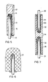
- the rod 1 made of a unidirectionally reinforced fiber composite material is inserted in an anchor sleeve 2, in which the rod is anchored and via which the forces can be transmitted in a known manner.
- the anchor sleeve 2 is drilled axially and provided with a thread 3.
- the end of the rod 1 is widened with a cross nail 4.
- the entire remaining free space inside the anchor sleeve is completely filled with a potting compound 5.
- FIGS. 2 and 3 are the same as in FIG. 1.
- Fig. 4 shows a suitable expansion element.
- FIG. 6 a masonry anchor is shown. Under certain circumstances, a metallic anchor sleeve can be dispensed with. Adequate profiling of the bore can be produced, for example, by drilling into hardened concrete 20 or by pouring cores, which are removed again after the concrete has hardened.
- FIG. 7 shows how profiles can be connected to one another. The two rods 30, 31 are inserted in an anchor sleeve 32, which is drilled out from both sides and is internally profiled 33. The rod ends are widened 34 and cast in 35. The multiple anchors serve to connect several profiles with aligned and / or mutually perpendicular profile axes.
- the anchor sleeves were made of St 52 material, had an outer diameter of 25 mm, were 80 mm long and were provided with a through hole in which M 14 threads were cut.
- the sleeves were temporarily closed on one side and filled to about 3/4 of their length with a filler-free cold-curing epoxy resin and the profile ends were pressed in firmly with the cross nails so that the resin completely filled all the spaces between the threaded holes, the rod segments and the cross nails.
- the anchorages thus produced failed in the tensile test at a load of 65,300 N.
- a round rod with a diameter of 7.5 mm made of a fiber composite material based on an unsaturated polyester resin and approx. 80% by weight of unidirectionally oriented glass fibers was cut in a cruciform shape at both ends by approx. 35 mm in length and a cross diameter of 6 mm were pressed into the profile with the tip to such an extent that they were fixed by the elastic clamping force of the profile segments.
- the anchor sleeve stock was made of St 52 material and had an outer diameter of 20 mm.
- An M 12 thread was cut into the blind hole 65 mm deep. About 50 g of a fast-curing casting compound were poured into the blind hole and the end of the profile was pressed firmly in with the cross nail.
- the potting compound completely filled all the spaces between the threaded hole, the rod and the cross nails. Force transmission elements manufactured in this way failed in the tensile test at a load of 58,600 N.
Landscapes
- Engineering & Computer Science (AREA)
- General Engineering & Computer Science (AREA)
- Mechanical Engineering (AREA)
- Architecture (AREA)
- Civil Engineering (AREA)
- Structural Engineering (AREA)
- Joining Of Building Structures In Genera (AREA)
- Reinforcement Elements For Buildings (AREA)
Applications Claiming Priority (2)
| Application Number | Priority Date | Filing Date | Title |
|---|---|---|---|
| DE3118492 | 1981-05-09 | ||
| DE3118492A DE3118492A1 (de) | 1981-05-09 | 1981-05-09 | Krafteinleitungselement fuer faserverbundwerkstoffe |
Publications (3)
| Publication Number | Publication Date |
|---|---|
| EP0064652A2 true EP0064652A2 (fr) | 1982-11-17 |
| EP0064652A3 EP0064652A3 (en) | 1985-12-27 |
| EP0064652B1 EP0064652B1 (fr) | 1988-09-14 |
Family
ID=6131919
Family Applications (1)
| Application Number | Title | Priority Date | Filing Date |
|---|---|---|---|
| EP82103491A Expired EP0064652B1 (fr) | 1981-05-09 | 1982-04-24 | Dispositif d'ancrage pour des matériaux composites de filaments |
Country Status (3)
| Country | Link |
|---|---|
| US (1) | US4526492A (fr) |
| EP (1) | EP0064652B1 (fr) |
| DE (2) | DE3118492A1 (fr) |
Cited By (1)
| Publication number | Priority date | Publication date | Assignee | Title |
|---|---|---|---|---|
| DE3707292A1 (de) * | 1987-03-06 | 1988-09-15 | Korte Jungermann Hans Werner | Verfahren zur verankerung eines ankerbolzens |
Families Citing this family (8)
| Publication number | Priority date | Publication date | Assignee | Title |
|---|---|---|---|---|
| GB2364756B8 (en) * | 2000-07-14 | 2017-06-14 | Vitec Group Plc | Improvements in or relating to methods of forming joints between elongate members and sockets |
| RU2182642C1 (ru) * | 2000-11-22 | 2002-05-20 | Пышнов Виктор Николаевич | Насосная штанга (варианты) |
| RU2232865C2 (ru) * | 2002-05-24 | 2004-07-20 | Пышнов Виктор Николаевич | Насосная штанга |
| DE10232762A1 (de) * | 2002-07-18 | 2004-02-12 | Kew Kunststofferzeugnisse Gmbh Wilthen | Befestigungsmasse zum Fixieren eines Befestigungselementes und Verfahren |
| DE102007011987A1 (de) * | 2007-03-09 | 2008-09-18 | Technische Universität Chemnitz | Zugstabsystem und Verfahren zum Erstellen eines Zugstabsystems |
| US11391312B2 (en) * | 2012-06-19 | 2022-07-19 | Megalex Joint, Llc | Method for creating a high tensile strength joint for connecting rods and fittings |
| US10132343B2 (en) * | 2012-06-19 | 2018-11-20 | Megalex Joint, Llc | High tensile strength joint for connecting rods and fittings |
| HU231446B1 (hu) * | 2020-08-26 | 2023-11-28 | Pauger Kft. | Eljárás végterminál rögzítésére és hasító eszköz |
Family Cites Families (15)
| Publication number | Priority date | Publication date | Assignee | Title |
|---|---|---|---|---|
| US87778A (en) * | 1869-03-16 | of titusville | ||
| US90935A (en) * | 1869-06-08 | Improved coupling for pump-rods | ||
| US52793A (en) * | 1866-02-20 | Improved pipe-coupling | ||
| US974719A (en) * | 1910-03-30 | 1910-11-01 | Charles Stevenson | Wire cable, socket, and coupling. |
| US1381779A (en) * | 1919-09-25 | 1921-06-14 | Thomas M Williams | Dead-end clamp for cables |
| US2426920A (en) * | 1942-08-20 | 1947-09-02 | Wilhelm B Bronander | Method of forming and applying cooling fins to tubular members |
| US2874937A (en) * | 1955-11-25 | 1959-02-24 | Edward F Higgins | Corrosion-resistant sucker rod and method of constructing same |
| US3129282A (en) * | 1962-08-23 | 1964-04-14 | Anderson Electric Corp | Strain insulators |
| US3328229A (en) * | 1963-11-06 | 1967-06-27 | Dow Chemical Co | Method and apparatus for attaching load bearing members to low strength bodies |
| US3552787A (en) * | 1968-10-28 | 1971-01-05 | Alfred A Yee | Wire cage-type splice sleeve for reinforcing bars |
| GB1382054A (en) * | 1971-05-20 | 1975-01-29 | Fosroc Ag | Fixing bolts in blind holes |
| GB1408366A (en) * | 1973-06-22 | 1975-10-01 | Ici Ltd | Anchor bolt |
| GB1524469A (en) * | 1976-08-13 | 1978-09-13 | Ici Ltd | Dowel device for grouting in a drillhole |
| US4247224A (en) * | 1978-12-14 | 1981-01-27 | Ppg Industries, Inc. | Method for installing a mine roof bolt |
| DE2903694A1 (de) * | 1979-01-31 | 1980-08-14 | Gebirgssicherung Gmbh | Gebirgsanker |
-
1981
- 1981-05-09 DE DE3118492A patent/DE3118492A1/de not_active Withdrawn
-
1982
- 1982-04-22 US US06/371,028 patent/US4526492A/en not_active Expired - Fee Related
- 1982-04-24 DE DE8282103491T patent/DE3279034D1/de not_active Expired
- 1982-04-24 EP EP82103491A patent/EP0064652B1/fr not_active Expired
Cited By (1)
| Publication number | Priority date | Publication date | Assignee | Title |
|---|---|---|---|---|
| DE3707292A1 (de) * | 1987-03-06 | 1988-09-15 | Korte Jungermann Hans Werner | Verfahren zur verankerung eines ankerbolzens |
Also Published As
| Publication number | Publication date |
|---|---|
| EP0064652A3 (en) | 1985-12-27 |
| EP0064652B1 (fr) | 1988-09-14 |
| DE3118492A1 (de) | 1982-12-02 |
| DE3279034D1 (en) | 1988-10-20 |
| US4526492A (en) | 1985-07-02 |
Similar Documents
| Publication | Publication Date | Title |
|---|---|---|
| EP2817465B1 (fr) | Dispositif d'introduction de force dans des éléments de traction à partir de lamelles de bandes plates en matière synthétique renforcées en fibres | |
| EP2606185B1 (fr) | Dispositif d'introduction de force dans des éléments de traction constitués de lamelles plates en matière plastique renforcée par des fibres | |
| EP3578832B1 (fr) | Procédé d'agencement d'une vis de béton cellulaire dans le béton cellulaire, utilisation et agencement | |
| WO2014154207A1 (fr) | Agencement structural et procédé pour fixer un échafaudage sur un mur de bâtiment | |
| EP0064652B1 (fr) | Dispositif d'ancrage pour des matériaux composites de filaments | |
| EP1397601B1 (fr) | Tige d'ancrage | |
| EP1259679B1 (fr) | Ancrage pour element de traction precontraint et/ou charge et boite d'ancrage | |
| EP0188174A1 (fr) | Ancre pour la consolidation des parois dans des structures de cavité | |
| EP2977528B1 (fr) | Système de renfort d'un ouvrage et procédé destiné à renforcer un ouvrage doté d'un tel système de renfort | |
| EP0319736B1 (fr) | Méthode de fixation de boulons d'ancrage dans béton et masse compound | |
| DE102007057291A1 (de) | Verfahren zur Herstellung einer Eckverbindung für Beton-Fertigteile | |
| EP0015895A1 (fr) | Tirant pour l'ancrage d'éléments de construction dans un corps de fondement | |
| DE102009022828B4 (de) | Fachwerkträger einschließlich eines unterspannten Trägers sowie ein zugehöriges Verfahren zur Herstellung | |
| EP0739442B1 (fr) | Dispositif d'ancrage dans la roche, en plastique arme fibres de verre, pouvant etre tendu | |
| DE3879807T2 (de) | Doppelt wirkender Anker. | |
| EP1680559A1 (fr) | Dispositif comprenant une barre en plastique renforce par des fibres et servant a transmettre une charge a travers une couche calorifuge | |
| EP0996797A1 (fr) | Element de construction | |
| EP3135861B1 (fr) | Dispositif de fixation | |
| DE19958375A1 (de) | Vorrichtung zur Krafteinleitung und Verfahren zur Verbindung von inkompatiblen Werkstoffen | |
| EP0697530A1 (fr) | Boulon d'ancrage pour béton ou similaire | |
| DE7630026U1 (de) | Anschluss- und abdichtungseinrichtung zur ausbesserung von unerwuenschten hohlraeumen in vorzugsweise mauerwerk oder beton | |
| DE3631653C1 (en) | Anchorage for a rock bolt | |
| DE3124544A1 (de) | Manschette zur ummantelung von staeben, stahlbetonpfaehlen od.dgl. | |
| DE102024112883A1 (de) | Verankerung für vorgespannte Betonschwellen und Herstellungsverfahren | |
| DE8909880U1 (de) | Aus Holz gebildetes Konstruktionselement |
Legal Events
| Date | Code | Title | Description |
|---|---|---|---|
| PUAI | Public reference made under article 153(3) epc to a published international application that has entered the european phase |
Free format text: ORIGINAL CODE: 0009012 |
|
| 17P | Request for examination filed |
Effective date: 19820424 |
|
| AK | Designated contracting states |
Designated state(s): BE CH DE FR GB IT NL |
|
| PUAL | Search report despatched |
Free format text: ORIGINAL CODE: 0009013 |
|
| AK | Designated contracting states |
Designated state(s): BE CH DE FR GB IT LI NL |
|
| 17Q | First examination report despatched |
Effective date: 19870311 |
|
| R17C | First examination report despatched (corrected) |
Effective date: 19870527 |
|
| GRAA | (expected) grant |
Free format text: ORIGINAL CODE: 0009210 |
|
| ITF | It: translation for a ep patent filed | ||
| AK | Designated contracting states |
Kind code of ref document: B1 Designated state(s): BE CH DE FR GB IT LI NL |
|
| REF | Corresponds to: |
Ref document number: 3279034 Country of ref document: DE Date of ref document: 19881020 |
|
| ET | Fr: translation filed | ||
| GBT | Gb: translation of ep patent filed (gb section 77(6)(a)/1977) | ||
| PLBE | No opposition filed within time limit |
Free format text: ORIGINAL CODE: 0009261 |
|
| STAA | Information on the status of an ep patent application or granted ep patent |
Free format text: STATUS: NO OPPOSITION FILED WITHIN TIME LIMIT |
|
| 26N | No opposition filed | ||
| PGFP | Annual fee paid to national office [announced via postgrant information from national office to epo] |
Ref country code: DE Payment date: 19930317 Year of fee payment: 12 |
|
| PGFP | Annual fee paid to national office [announced via postgrant information from national office to epo] |
Ref country code: GB Payment date: 19930419 Year of fee payment: 12 |
|
| PGFP | Annual fee paid to national office [announced via postgrant information from national office to epo] |
Ref country code: BE Payment date: 19930427 Year of fee payment: 12 |
|
| PGFP | Annual fee paid to national office [announced via postgrant information from national office to epo] |
Ref country code: FR Payment date: 19930428 Year of fee payment: 12 |
|
| ITTA | It: last paid annual fee | ||
| PGFP | Annual fee paid to national office [announced via postgrant information from national office to epo] |
Ref country code: NL Payment date: 19930430 Year of fee payment: 12 Ref country code: CH Payment date: 19930430 Year of fee payment: 12 |
|
| PG25 | Lapsed in a contracting state [announced via postgrant information from national office to epo] |
Ref country code: GB Effective date: 19940424 |
|
| PG25 | Lapsed in a contracting state [announced via postgrant information from national office to epo] |
Ref country code: LI Effective date: 19940430 Ref country code: CH Effective date: 19940430 Ref country code: BE Effective date: 19940430 |
|
| BERE | Be: lapsed |
Owner name: BAYER A.G. Effective date: 19940430 |
|
| PG25 | Lapsed in a contracting state [announced via postgrant information from national office to epo] |
Ref country code: NL Effective date: 19941101 |
|
| NLV4 | Nl: lapsed or anulled due to non-payment of the annual fee | ||
| GBPC | Gb: european patent ceased through non-payment of renewal fee |
Effective date: 19940424 |
|
| PG25 | Lapsed in a contracting state [announced via postgrant information from national office to epo] |
Ref country code: FR Effective date: 19941229 |
|
| REG | Reference to a national code |
Ref country code: CH Ref legal event code: PL |
|
| PG25 | Lapsed in a contracting state [announced via postgrant information from national office to epo] |
Ref country code: DE Effective date: 19950103 |
|
| REG | Reference to a national code |
Ref country code: FR Ref legal event code: ST |