EP0064735A2 - Mandrin à mors multiples et outil ainsi qu'un ensemble de forets pour ce mandrin et méthode de production sans enlèvement de copeaux d'au moins une partie de l'outil - Google Patents
Mandrin à mors multiples et outil ainsi qu'un ensemble de forets pour ce mandrin et méthode de production sans enlèvement de copeaux d'au moins une partie de l'outil Download PDFInfo
- Publication number
- EP0064735A2 EP0064735A2 EP82103971A EP82103971A EP0064735A2 EP 0064735 A2 EP0064735 A2 EP 0064735A2 EP 82103971 A EP82103971 A EP 82103971A EP 82103971 A EP82103971 A EP 82103971A EP 0064735 A2 EP0064735 A2 EP 0064735A2
- Authority
- EP
- European Patent Office
- Prior art keywords
- clamping
- tool
- jaw
- chuck
- rib
- Prior art date
- Legal status (The legal status is an assumption and is not a legal conclusion. Google has not performed a legal analysis and makes no representation as to the accuracy of the status listed.)
- Ceased
Links
Images




Classifications
-
- B—PERFORMING OPERATIONS; TRANSPORTING
- B23—MACHINE TOOLS; METAL-WORKING NOT OTHERWISE PROVIDED FOR
- B23B—TURNING; BORING
- B23B31/00—Chucks; Expansion mandrels; Adaptations thereof for remote control
- B23B31/005—Cylindrical shanks of tools
-
- B—PERFORMING OPERATIONS; TRANSPORTING
- B23—MACHINE TOOLS; METAL-WORKING NOT OTHERWISE PROVIDED FOR
- B23B—TURNING; BORING
- B23B31/00—Chucks; Expansion mandrels; Adaptations thereof for remote control
- B23B31/02—Chucks
- B23B31/10—Chucks characterised by the retaining or gripping devices or their immediate operating means
- B23B31/12—Chucks with simultaneously-acting jaws, whether or not also individually adjustable
- B23B31/1207—Chucks with simultaneously-acting jaws, whether or not also individually adjustable moving obliquely to the axis of the chuck in a plane containing this axis
- B23B31/1215—Details of the jaws
-
- B—PERFORMING OPERATIONS; TRANSPORTING
- B23—MACHINE TOOLS; METAL-WORKING NOT OTHERWISE PROVIDED FOR
- B23B—TURNING; BORING
- B23B2231/00—Details of chucks, toolholder shanks or tool shanks
- B23B2231/02—Features of shanks of tools not relating to the operation performed by the tool
- B23B2231/028—Lugs
Definitions
- the invention relates to a multi-jaw chuck for connecting differently thick clamping shanks of tools to a drive shaft of a machine, which has a jaw holder which is firmly connectable with its rear end to the drive shaft and comprises at least two jaws which are provided with clamping surfaces and for clamping 4des Clamping shank of the tool are movably mounted in the jaw holder in a clamping direction.
- Multi-jaw chucks of this type are known for drills, chisels, screwdriver bits and the like tools.
- the invention is concerned with the manufacture of tool holders for tools on which axial impacts must be exerted during machining, as is the case, for example, with drills in impact drills and in rotary hammers.
- Impact drills are drilling machines that have a multi-jaw chuck, in particular a ring gear chuck, as a tool holder for gripping clamping shafts of different thicknesses, which is fastened to the drive shaft designed as a spindle, which is axially displaced by a ratchet disc in intermittent movements.
- the impacts exerted by the ratchet disc on the drive shaft are transmitted from the latter via the multi-jaw chuck to the drill, which is clamped firmly and axially immovably in the chuck.
- a hammer drill is a drilling machine in which a club is moved axially back and forth in a tube by a pneumatically or mechanically driven flying piston.
- the bat which can also be formed as part of the flying piston, strikes the rear end of the clamping shaft of the tool, which is held axially displaceably in the tool holder.
- the individual blows are many times larger than with an impact drill.
- the tool holder is rotated in whole or in part and transfers this to the drilling tool. It forms a structural unit with the hammer drill.
- the various tools In the case of a rotary hammer, the various tools must therefore all have the same clamping shank in order to fit in the tool holder. This significantly increases the manufacturing costs for the tools.
- the jaw holder of a multi-jaw chuck for clamping different thickness clamping shanks was provided with an insertion end which was adapted to the tool holder of the respective rotary hammer.
- the impact energy is transmitted from the racket to the insertion end of the multi-jaw chuck and from the bottom of the jaw holder of the multi-jaw chuck to the drill firmly clamped in it.
- this attempt failed because multi-jaw chucks are only suitable for the transmission of relatively weak impacts, such as occur with impact drills.
- the multi-jaw chucks used in this way were very quickly destroyed by the strong impacts due to their relatively complicated structure. For this reason, this solution path is not followed by experts. But even if this solution had proven to be accessible, the disadvantage of the reduction in drilling capacity described above in connection with the adapter would still have remained.
- the invention is based on the object of designing a multi-jaw chuck in such a way that it can also be used in rotary hammers and similar machines in which blows must be carried out by a racket directly on the rear end of the tool.
- racket is to be understood as any axially moved body which acts directly on the rear end of a tool axially displaceable in a tool holder.
- the invention opens up a completely new field of application for multi-jaw chucks, namely the full application in rotary hammers, thereby creating the possibility of also providing the tools for rotary hammers, similar to the tools for impact drills and the like, with a clamping shank that is not the one Tool holder of the drive machine, but the tool shank is adapted.
- a rotary hammer in which only the rear end, namely the clamping shank, with at least one molded-on counter surface for the cooperation Kung is provided with the driving surface of the jaw, for example, that this end is made out of round.
- Characteristic a ensures that the torque of the drive shaft of the machine is transmitted to the tool even when the tool shaft is clamped loosely in the multi-jaw chuck and permits axial movement.
- Characteristic b) ensures that, despite the use of a multi-jaw chuck, a racket, e.g. a hammer drill, can act directly on the rear end of the tool without the multi-jaw chuck itself being exposed to the blows.
- a racket e.g. a hammer drill
- the invention also relates to a tool with a clamping shank for the multi-jaw chuck according to the invention. Since the tool shank of a tool used in the multi-jaw chuck according to the invention can only be clamped in the multi-jaw chuck so loosely that a displacement of the same caused by the blows on the rear end of the tool is possible in the chuck, at least one counter surface must be formed on the clamping shaft for interaction with the driving surface of the jaw of the multi-jaw chuck.
- the invention has the purpose of designing tools of this type in such a way that their clamping shanks do not have to be adapted to the tool holders of the same, as in the known hammer drills, at least for a relatively large range of tool sizes, but can only be adapted to the tool shanks of the tools.
- the aim is to create the possibility that tools of this type have a continuous cylindrical surface for the tool shank and the clamping shank.
- the invention is therefore also based on the object of providing a tool in which a clamping shank with a very small diameter can also be provided with a counter surface which can interact effectively with the driving surface provided on the jaw of the multi-jaw chuck, which also has clamping shanks with large dimensions Diameters must be adjusted.
- This task is for a tool with a clamping shank, which is provided with an axially extending straight or helical rib and is provided for clamping in a multi-jaw chuck, in which at least one jaw is provided with an axial, straight or helically extending groove, solved according to the invention in that the rib is arranged asymmetrically with respect to all diametrical planes of the clamping shaft.
- the groove in the clamping surface of a jaw of a multi-jaw chuck according to the invention must be so wide that it can accommodate the rib of a large tool, which is so wide that it can transmit the large torque required for the large tool. Due to the inventive design can now with a small tool to transfer the smaller torque the rib are made much narrower than the width of the groove and it can be achieved that the trailing side surface of the rib lies essentially completely against the adjacent side surface of the groove and its width is nevertheless adapted to the small diameter of the clamping shank of the smaller tool , so that the above-mentioned asymmetrical arrangement of the rib results.
- the rib length can also be selected accordingly for further adaptation to the torque to be transmitted.
- the side surface of the rib lagging when the tool rotates is arranged in a diametral plane of the clamping shank. This creates optimal conditions for the transmission of the torque from the chuck to the tool. If the leading side surface of the rib with the trailing side surface forms an acute angle other than zero, then the width of the rib increases towards its foot connecting it with the clamping shank, so that it has much greater forces at the same height can transmit. With clamping shanks with a large diameter, this has the advantage that the rib can be made lower. Clamping shafts with a small diameter again have the advantage that, despite the small amount of material that can be formed from the cylindrical shaft to form the rib, the rib also has sufficient strength for the transmission of the required torque.
- the leading edge when the tool rotates Side surface of the rib is provided with at least one lateral projection. This ensures that not only the torque when rotating the multi-jaw chuck can be properly transferred from the tool to the rib, but also that the tool cannot move in the opposite direction within the result of the engagement of the narrow rib in the wide groove Game can be rotated.
- the invention also relates to a drill set which consists of at least two drills for bores with different diameters and whose individual drills can be used for a rotary hammer with a multi-jaw chuck according to the invention.
- the drills previously used in rotary hammers always had to have a clamping shank adapted to the tool holder of the rotary hammer.
- the invention is based on the object of creating a drill set for the above-mentioned purpose, in which the individual drills can be produced very easily.
- clamping shafts of all the drills in the set form a continuous cylindrical outer surface with the respective tool shafts and in that the clamping shafts are provided with at least one surface interrupting the cylindrical outer surface.
- a particularly preferred embodiment of this drill set consists in that the surfaces interrupting the cylindrical circumference of the clamping shafts of the individual drills Chen are formed by the side surfaces lagging when the tool rotates, at least one axial straight or helical rib and that the drills with larger diameters have broad and the drills with smaller diameters have narrower ribs.
- the ribs are arranged asymmetrically with respect to all of the dimensional planes of the clamping shank.
- the invention also relates to a method for non-cutting shaping of at least a part of the tool, namely the clamping shank of the same. Due to the fact that the arrangement of the rib on the clamping shaft according to the invention makes it asymmetrical with respect to all diametral planes, a torque occurs during the non-cutting shaping of a blank into this asymmetrical shape, by means of which the blank is then rotated in the die during the shaping and thereby the desired one Form is not achieved.
- the invention is therefore based on the object of specifying a method by which this turning of the blank in the die can be avoided.
- a die is used for forming at least one pair of tool parts which are arranged in mirror image with respect to one another and abut one another with the same ends in order to form a tool part which is asymmetrical with respect to all the diametral planes, in that this die is used for the entire length at least one pair of the blank-extending tool parts is formed into the desired shape and that the pair of tool parts thus obtained is then divided into the individual tool parts. This will be in one and the same Blank when molding the two tool parts of a pair causes opposite torques that cancel out within the blank.
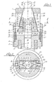
- the cavity 6 has two guide planes 8 lying opposite one another and converging towards the front opening 7 and two parallel guide planes 9 for two cheeks 11.
- the mutually parallel guide planes 9 have, in their edges, which adjoin the converging guide planes 8, guide grooves 12, in which guide strips 13 formed on the jaws 11 engage.
- a cylindrical opening 14 coaxial with the axis 5 opens, which is provided in the rear part 2 'of the jaw holder 3 and into which a firing pin 15 of a racket, not shown, shown in dashed lines in the drawing of a hammer drill and the rear end of a clamping shank 16 or 116 of a drill 16 'or 116' which is clamped in the multi-jaw chuck shown and shown in broken lines in FIGS. 1 and 3.
- the rear part 2 of the jaw holder 3 is provided with an annular groove 17 coaxial with the axis 5, which is provided in its radially inner wall surface with an external thread 18, by means of which the jaw holder a and thus that entire two-jaw chuck can be screwed onto a tubular drive shaft 19 of a rotary hammer, which is axially immovable in the rotary hammer, but rotatably mounted and driven by the drive of the hammer drill for rotation about its axis in the direction of the arrows shown in FIGS. 2 and 4 and for the guidance of the axially moved back and forth in the hammer drill, provided with the striker 15.
- the two jaws 11 have mutually parallel flat outer surfaces 21, with which they bear against the mutually parallel guide planes 9, and plane surfaces 22 inclined with respect to the axis 5, with which they bear against the guide planes 8 converging towards the opening 7, so that the guide planes 8 and 9 together with the guide grooves 12 form positive guides for an axial displacement and a radial displacement of the jaws 11 caused thereby.
- pins 24 engage loosely, which extend through slots 25 in the jaw holder 3 parallel to the guide planes 9, protrude radially outwards and are screwed into threaded bores 26 of a sleeve 27 which are axially displaceably mounted on the jaw holder 3 and acts on a helical compression spring 28 which tries to push the sleeve 27 so far forward until the pins 24 abut the front ends 29 of the slots 25.
- the jaws 11 form two diverging clamping surfaces 31, which in the exemplary embodiment shown are designed as planes and are provided for contact with the cylindrical clamping shaft 16, 116.
- These clamping surfaces 31 are arranged symmetrically to an axial plane of the jaw holder 3 which is parallel to the guide planes 9 and merge at their mutually adjacent edges into an axially extending groove 32, the side surface of which which follows the rotation of the jaw holder 11 forms a driving surface 33 which is in contact with a corresponding counter surface 34, 134 of the clamping shaft 16 or 116 of the drill cooperates, which in turn is formed by a rib 35 or 135 which is compressed on the clamping shaft 16, 116.
- the parts of the jaws 11 forming the clamping surfaces 31 are through
- Slots 36 interrupted, which are arranged so offset with respect to one another in the two jaws 11 and are so wide that, when the jaws are pushed together radially, the prong-like parts 37 of one jaw, which form the clamping surfaces, engage in the slots 36 of the other jaw, as shown in FIG. 4 can be seen.
- the grooves 32 in the jaws 11 are limited to the front so that the groove ends form stop surfaces 38 which, together with the stop surfaces 39, 139 formed by the front ends of the ribs 35, 135 of the clamping shaft 16, 116 which are essentially perpendicular to the axis 5, form stops limit the axial displaceability of the clamping shaft 16, 116 to the front, so that the clamping shaft 16, l16 clamped in the two-jaw chuck cannot fall out of the chuck despite a loose clamping.
- the end of the clamping shaft containing the ribs 35, 135 is only so long that when the front end of the ribs 35, 135 abuts the front groove end, the front end of the firing pin 15 is in its foremost position due to its limited stroke at a distance from the rear end of the clamping shaft 16, 116.
- the two jaws 11 When not in use, the two jaws 11 are pushed so far forward by the spring 28 that the pins 24 abut the front ends 29 of the slots 25.
- the rear ends 35 'of the ribs 35 / are bevelled by 45 with respect to the axis 5. If drilling is to be carried out with a hammer drill, to whose drive shaft 19 the multi-jaw chuck described above is screwed, the drill required in each case is pressed with its clamping shank 16, 116 against the front ends of the jaws 11 (FIG.
- the jaws 11 Once provided on the clamping shank 16,116 ribs 35 engage the grooves 135 in 32 of the jaws 11, the jaws 11 to jump back radially until their clamping surfaces 31 on the periphery of the shank 16, loose fitting by pressure of the spring 1 sixteenth If in this position the clamping shaft 16 116 is drilled with the hammer drill, then the drill is pushed backwards by the working pressure, its rearmost position being defined by the rearmost position of the club. Due to the blows exerted by the firing pin 15, the drill is pushed forward, which is made possible by the loose contact of the clamping surfaces 31 on the clamping shaft 16, 116.
- the two-jaw chuck is not burdened by these impacts because the stroke of the racket is limited, as stated above, and therefore the axially displaceable drill with its stop faces 39 / does not hit the stop faces 38 of the jaws 11 due to the strikes of the firing pin. So that the rear end of the clamping shaft 16 / cannot hit the firing pin 15 in its rearmost position, the grooves 32 can also be limited at their rear ends.
- drills with differently strong clamping shafts 16, 116 can be clamped in the two-jaw chuck.
- the rotation of the An Drive shaft 19 of the hammer drill through the driver surfaces 33 of the jaws 11 on the counter surfaces 34, 134 of the ribs 35, 135 and via the clamping shaft 16, 116 transferred to the drill.
- FIG. 1 it can be seen from FIG. 1 that in this embodiment the rear end of the thickest clamping shaft / is guided in the opening 14.
- the firing pin 14 can also be designed so that it engages in the space between the rear end of the jaws 11 and the part 2.
- a chuck with more than two jaws e.g. a three-jaw chuck. It is also not necessary for the guide surfaces of the jaw holder and the surfaces of the jaws lying against them to be flat. These can also e.g. be cylindrical. In such a case, however, corresponding guide parts must be provided for the guide strips 13, which enable axial guidance of the jaws; however prevent an unguided radial movement and rotation about the axis 5.
- the grooves 32 provided in the jaws 11 for the correspondingly shaped ribs 35, 1: of the clamping shaft 16, 116 can be one have a helical course, which is directed such that the torque transmitted from the jaws 11 to the clamping shaft 16, 116 causes an axial force component on the clamping shaft 16, 116, by means of which the clamping shaft is pressed backwards.
- FIG. 5 to 7 an embodiment of a clamping shaft of a drill is shown, the chuck with the above-described and shown in the drawing chuck or a suitably designed multi-jaw chuck can be used.
- the clamping shank 116 shown there of a thin drill 116 ' has the same diameter like the drill 116 'and is provided with two ribs 135 which are narrower than the jaw groove 32.
- each of these narrower ribs 135 is intended to contact the driving surface 33 with its counter surface 134 over the entire surface.
- the counter surface 134 must be arranged at the same distance from the diametral plane parallel to it as the corresponding counter surface of a rib which fully fills the groove 32.
- the rib 135 is arranged asymmetrically with respect to all the diametral planes of its clamping shaft 116.
- the side surface of the rib lying opposite the counter surface 134 and leading when the drill rotates lies in the diametral plane of the clamping shank 116 parallel to the counter surface.
- each rib 135 not only a positive connection of its counter surface 134 to the driving surface 33 of the To obtain a jaw, but also a positive connection of the surface of the rib opposite the counter surface 134 with the surface of the groove 32 opposite the driving surface 33 and thereby preventing a relative rotation of the drill shank to the jaws 11 in both directions, is approximately in the central region of the Rib 135 an indentation 141 is provided, which rests on the surface of the groove 32 opposite the driving surface 33 when the rib 135 engages in the groove 32 of the jaw 11.
- a further embodiment of a drill 216 ' is shown, in which the rib 235 is also narrower than the groove 32.
- the rib 235 is arranged asymmetrically with respect to all diametrical planes of the clamping shaft 216' and theirs the opposite surface 234, which leads when the drill rotates, lies in the diametral plane of the clamping shank parallel to the counter surface 234.
- a flattened portion 241 is provided at the rear end of the rib, which forms a corresponding projection and thus also prevents the drill bit from being rotated back and forth in the chuck.
- the rear end faces of the ribs as well as the end faces 35 'and 135' of the ribs 35 and 135 form an angle of 45 ° with the axis of the clamping shank 116 and 216, this beveling of the rear end in the exemplary embodiment 8 to 10 is partially formed by the flat 241.
- the front ends of the ribs 135 and 235 form the substantially right here stop surfaces 139 and 239 running at an angle to the axis of the shaft.
- the racket engages in the opening 14 of the jaw holder 3 by means of the firing pin 15 in order to be able to act on the end of the clamping shaft 16.
- the clamping shaft of the tool and the hammer drill can, however, also be designed such that the clamping shaft engages through the opening 14 in the hammer drill so that a racket can be used which does not have to engage in the opening 14 in order to act directly on the end of the clamping shaft to be able to.
- This has the advantage that the diameter of the opening 14 and the racket do not have to be coordinated with one another, so the multi-jaw chuck only has to be adapted to the drill hammer in relation to the screw connection, but otherwise only to the tool shanks.
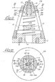
- FIGS. 11 and 12 a second embodiment of a two-jaw chuck is shown.
- the parts of this exemplary embodiment corresponding to the first exemplary embodiment illustrated in FIGS. 1 to 4 are designated by reference numerals enlarged by 100, so that reference is made to the description of the first exemplary embodiment by this reference.
- FIGS. 11 and 12 differs from the first embodiment in that here the jaw holder 103 has a conical outer surface and that the prong-like parts 137 of the jaws 111 are made so long that they also when clamping the thickest clamping shaft, such as which is shown in dashed lines in Fig. 11, interlock. As a result, the two jaws are connected to one another in the most expanded position for a common axial movement.
- a further difference is that the pins 124 which pass through the slots 125 are firmly ver with the jaws 111 here bound, namely screwed and that these pins have slightly protruding heads 124 'from the conical outer surface of the jaw holder l03, by means of which the jaws 111 can be axially displaced by hand against the force of the helical spring 128 acting directly on the jaws 111, for example to be able to take out a drill clamped in the chuck.
- the converging guide planes 108 of the jaw carrier are connected by the slots 125 in the central plane. running surface lines parallel to the conical outer surface.
- the grooves 132 in the clamping surfaces 131 of the jaws 111 are arranged asymmetrically with respect to all diametrical planes of the chuck, in such a way that the driving surfaces are arranged in a diametrical plane of the chuck.
- the side surfaces of the grooves 132 opposite the driver surfaces 133 are parallel to a diametrical plane of the chuck which follows them and thus form an acute angle with the driver surface.
- the arrangement of this side surface of the groove 132 opposite the driver surface is such that it lies in a tangential plane to the clamping shaft when the thickest clamping shaft is used. This has the advantage that the clamping shank of a clamped tool can also have appropriately shaped ribs, which have a particularly high strength due to this shape.
- FIG. 12 shows the thinnest clamping shaft 516 that can be clamped with the illustrated chuck, in which the ribs 535 are also arranged asymmetrically with respect to all diametral planes, in such a way that the trailing side surfaces, namely the counter surfaces 534, lie in a diametrical plane of the shaft lie and the opposite side surfaces of the ribs 535 are arranged in tangential planes of the shaft.
- the ribs have a particularly high strength, since their thickness increases with the rib base connected to the clamping shaft.
- This exemplary embodiment differs from the two previously described exemplary embodiments primarily in that here the converging guide planes 308 converge towards the rear, that is to say towards the machine, or in other words, diverge towards the tool. 11 and 12, the two jaws 311 are connected to one another by the prong-like parts 337 in their most expanded position as shown in FIGS. 13 and 14.
- Helical compression springs 328 are provided in the guide planes 308 of parallel bores of the jaw holder 303 and are connected to the jaws 311 by means of pins 324 which engage in these bores through slots 325 and which press them into their expanded position in the opposite manner to the previously described exemplary embodiments.
- a sleeve 327 which is guided on the cylindrical outer surface of the jaw holder 303 and serves as a handle, is also provided here, but not with the jaws.
- 311 is connected, but protrudes in front of the front end of the jaw holder 303 and is provided at its foremost end with an inner, to the outer jacket coaxial, cylindrical edge 327 'which bears against the front end face of the jaws 311, so that by means of this sleeve 327 Jaws 311 can be shifted from the foremost position shown in solid lines in FIG. 13 to the rearmost position shown in broken lines against the force of the springs 328.
- An inner surface of the outer casing of the sleeve 327 is provided with an axial groove 341, into which branches 342 which extend in diametrical planes and which have small indentations 343 at their ends on the front side, so that this axial groove 341 with the branches 342 in cooperation with one provided on the jaw holder 303 Pin 344 forms a number of bayonet locks corresponding to the number of branches 342 for the different positions of sleeve 327.
- the groove 341 is closed at its rear end so that the sleeve 327 cannot fall off the jaw holder 303.
- the grooves 332 of this exemplary embodiment are designed in cross section in the same way as in the exemplary embodiment according to FIGS. 11 and 12.
- This configuration of the grooves and the corresponding configuration of the ribs result, like that, from FIG. 12 shows that within the grooves of the clamping shaft 516 of a thinner tool, the clamping surfaces 131 and 331 hold it only at two diametrically opposite points.
- the grooves 132 and 332 are limited not only at their front ends forming the stop surfaces 138 and 338, but also at their rear ends, so that the clamping surfaces 131 and 331 in front of and behind the grooves are not interrupted by them and thereby fulfill the desired support function.
- FIG. 15 shows a set of three drills 16 ', 116' and 216 ', the clamping shanks 16 or 116 and 216 of which form a continuous cylindrical outer surface with the respective drill shanks and each with two diametrically opposite ribs 35, 135 and 235 are provided.
- the distance of the front end of the rib 35 of the thickest clamping shaft 16 is the smallest of the three drills from the rear end of the clamping shaft. This distance of the front end of the rib increases with decreasing diameter in the clamping shaft 116 and in the clamping shaft 235.
- the clamping shafts with ribs shown in FIGS. 5 to 10 are the clamping shafts according to FIG. 15 provided with the same reference numbers, so that a detailed description thereof is unnecessary.
- FIG. 16 shows the clamping shafts 316, 416 and 516 of three drills forming a second set of drills.
- the bits of this set are provided with grooves 132 and 332 fitted ribs 335, 435 and 535, but in which, unlike the set shown in Fig. 15, the distances of the front ends of the ribs from the rear end of the shaft decrease with decreasing Remove the shaft diameter.
- the counter surfaces 334, 434 and 534 which cooperate for the interaction of the driving surface 133 and 333 of the jaw grooves 132 and 332, are in a diametral plane of the shank, while the other side surface forms an acute angle with the counter surface, in this way that the leading side surfaces opposite the mating surfaces of the ribs 335, 435, 535 lie in tangential planes of the clamping shaft.
- the ribs 435 and 535 of the thinner clamping shafts 416 and 516 are thinner than the rib 334 of the thickest clamping shaft 316 and therefore have on the side opposite the counter surface 434 and 534, a projection formed by an indentation 441 or a flat 541, which forms a stop surface on the surface opposite the driving surface of the groove.
- the front ends of the ribs 334, 434 and 534 form with those of the front ends of the grooves 132 and 332 stop surfaces 138 and 338 interacting stop surfaces 339 and 439 and 539.
- Tools of the type described here are produced by chipless shaping of a rod-shaped or tubular blank, the blank being formed into the desired shape in a die by pressing, forging or hammering.
- the die can be produced in such a way that no torque is exerted on the blank when the blank is formed.
- a die is used for forming a tool part that is asymmetrical with respect to all diametral planes, for example a clamping shank designed in this way, for at least one pair of tool parts arranged in mirror image to one another and abutting one another with the same ends.
- a blank is then inserted into such a die, which extends over the entire length of the die and thus at least one pair of tool parts.
- at least one pair of tools is thereby formed, which abut one another in mirror image with the same ends.
- 17 shows a pair of tools produced in this way, in which two clamping shafts 416 cross one another with their rear ends at the dashed line go. It is thereby achieved that opposite torques are caused on the blank when the two clamping shafts 416 are formed, which are canceled out at the transition from one shaft to the other.
Landscapes
- Engineering & Computer Science (AREA)
- Mechanical Engineering (AREA)
- Gripping On Spindles (AREA)
- Turning (AREA)
Applications Claiming Priority (2)
| Application Number | Priority Date | Filing Date | Title |
|---|---|---|---|
| DE19813118691 DE3118691A1 (de) | 1981-05-12 | 1981-05-12 | Mehrbackenfutter und werkzeug sowie bohrersatz fuer das mehrbackenfutter und verfahren zum spanlosen formen mindestens eines teiles des werkzeuges |
| DE3118691 | 1981-05-12 |
Publications (2)
| Publication Number | Publication Date |
|---|---|
| EP0064735A2 true EP0064735A2 (fr) | 1982-11-17 |
| EP0064735A3 EP0064735A3 (fr) | 1983-07-20 |
Family
ID=6132029
Family Applications (1)
| Application Number | Title | Priority Date | Filing Date |
|---|---|---|---|
| EP82103971A Ceased EP0064735A3 (fr) | 1981-05-12 | 1982-05-07 | Mandrin à mors multiples et outil ainsi qu'un ensemble de forets pour ce mandrin et méthode de production sans enlèvement de copeaux d'au moins une partie de l'outil |
Country Status (2)
| Country | Link |
|---|---|
| EP (1) | EP0064735A3 (fr) |
| DE (1) | DE3118691A1 (fr) |
Cited By (3)
| Publication number | Priority date | Publication date | Assignee | Title |
|---|---|---|---|---|
| EP0126472A3 (fr) * | 1983-05-20 | 1986-07-16 | Muzzy, Kenneth R. | Mandrin à changement rapide d'outil |
| US4752165A (en) * | 1983-12-09 | 1988-06-21 | Robert Bosch Gmbh | Arrangement for torque transmitting, and tool cooperating therewith |
| EP1375078A1 (fr) * | 2002-06-21 | 2004-01-02 | HILTI Aktiengesellschaft | Adaptateur de tiges et porte-outil pour un outil à percussion |
Families Citing this family (6)
| Publication number | Priority date | Publication date | Assignee | Title |
|---|---|---|---|---|
| DE3241528C2 (de) * | 1982-11-10 | 1986-04-10 | Eugen Lutz GmbH u. Co Maschinenfabrik, 7130 Mühlacker | Werkzeugspannfutter für einen Bohrhammer |
| DE3310146C2 (de) * | 1983-03-21 | 1985-08-14 | Hilti Ag, Schaan | Bohrfutter für Schlagbohrbetrieb |
| DE3333856C2 (de) * | 1983-09-20 | 1987-02-12 | Licentia Patent-Verwaltungs-Gmbh, 6000 Frankfurt | Werkzeugaufnahme für Mehrnuthammerbohrer für einen elektropneumatischen Bohrhammer |
| DE3413432A1 (de) * | 1983-12-27 | 1985-07-04 | Gebrüder Heller GmbH Werkzeugfabrik, 2807 Achim | Bohrer fuer handbohrmaschinen |
| DE3500201A1 (de) * | 1985-01-05 | 1986-07-10 | Hawera Probst Gmbh + Co, 7980 Ravensburg | Spannfutter fuer handwerkzeugmaschinen |
| DE3515555A1 (de) * | 1985-04-30 | 1986-11-06 | Gebrüder Heller GmbH Werkzeugfabrik, 2807 Achim | Werkzeugaufnahme fuer bohrmaschinen, bohrvorrichtung sowie bohrer und bohrersatz |
Family Cites Families (28)
| Publication number | Priority date | Publication date | Assignee | Title |
|---|---|---|---|---|
| DE547768C (de) * | 1932-04-09 | Fr Haake Fa | Bohrfutter mit unter Schrauben- und Keilwirkung in Nuten des Gehaeuses gefuehrten Backen | |
| GB190910889A (en) * | 1909-05-07 | 1909-11-25 | Harold Williamson Lake | Improvements in Twist Drills. |
| US1104113A (en) * | 1913-04-07 | 1914-07-21 | Milo A Hamilton | Chuck. |
| CH74252A (de) * | 1916-09-15 | 1917-02-01 | Cesare Martini | Einspannvorrichtung für Werkstücke und Werkzeuge |
| CH83538A (de) * | 1919-02-21 | 1919-12-16 | Aebli Herzog Hermann | Selbstspannendes Spannfutter |
| FR598838A (fr) * | 1925-05-27 | 1925-12-26 | Mandrin pour forets | |
| US2159162A (en) * | 1936-07-29 | 1939-05-23 | American Mach & Foundry | Tap holder chuck |
| US2468874A (en) * | 1946-11-07 | 1949-05-03 | Karl G R Hawkins | Torsion driven tool |
| FR1006062A (fr) * | 1947-11-06 | 1952-04-18 | Mandrin perfectionné | |
| CH283139A (fr) * | 1949-10-10 | 1952-05-31 | Schuettel Roger | Outil taillant apte à être serré dans une pince. |
| US3161242A (en) * | 1960-05-31 | 1964-12-15 | Skil Corp | Rotary-hammer devices and tool element accessories therefor |
| DE1752155A1 (de) * | 1968-04-10 | 1971-05-13 | Hilti Ag | Werkzeug fuer Werkzeughalter fuer Bohrhaemmer |
| DE1943586C3 (de) * | 1969-08-27 | 1979-10-04 | Louis Aackersberg Fredensborg Mortensen (Daenemark) | Spiralbohrer |
| DE1957510C2 (de) * | 1969-11-15 | 1982-04-22 | Robert Bosch Gmbh, 7000 Stuttgart | Handgeführtes Schlagbohrgerät |
| DE2138566A1 (de) * | 1971-08-02 | 1973-02-15 | Siemens Ag | Verfahren zur herstellung von spiralbohrern und nach dem verfahren hergestelltes bohrersortiment sowie werkzeugaufnahme fuer nach dem verfahren hergestellte oder herzustellende spiralbohrer |
| US3837410A (en) * | 1973-05-23 | 1974-09-24 | R Maxwell | Rotary impact drill |
| US3982846A (en) * | 1973-12-05 | 1976-09-28 | Steinbach Ralph L | Tool device |
| DE2408557A1 (de) * | 1974-02-22 | 1975-09-04 | Bosch Gmbh Robert | Einrichtung zur drehmomentuebertragung auf vorzugsweise schlagbohrende werkzeuge |
| DE2405938C3 (de) * | 1974-02-08 | 1980-07-10 | Impex-Essen Vertrieb Von Werkzeugen Gmbh, 8800 Ansbach | Werkzeughalterung für Handschlaggeräte, insbesondere Elektro-Bohrhämmer |
| US4051905A (en) * | 1974-03-28 | 1977-10-04 | Gerbruder Heller | Drill for percussion drilling machines |
| DE2440082C3 (de) * | 1974-08-19 | 1982-02-25 | Durofac-Kartro A/S, Valby | Hammerbohrereinrichtung |
| DE2640175A1 (de) * | 1976-09-07 | 1978-03-09 | Ralph L Steinbach | Werkzeug |
| DE2640767A1 (de) * | 1976-09-10 | 1978-03-16 | Bosch Gmbh Robert | Werkzeughalter an einer handwerkzeugmaschine |
| DE2750219C2 (de) * | 1977-11-10 | 1985-11-21 | Friedrich Duss Maschinenfabrik GmbH & Co, 7265 Neubulach | Werkzeughalterung für einen Schlag- oder Drehschlaghammer |
| DE2754383C2 (de) * | 1977-12-07 | 1979-06-13 | Artur Dr.H.C. 7244 Waldachtal Fischer | Bohrer |
| DE2820125A1 (de) * | 1978-05-09 | 1979-11-22 | Bosch Gmbh Robert | Handwerkzeugmaschine |
| DE2842783A1 (de) * | 1978-09-30 | 1980-04-10 | Bosch Gmbh Robert | Futter fuer handwerkzeugmaschinen, insbesondere bohr- und/oder schlaghaemmer |
| DE3132450A1 (de) * | 1981-08-17 | 1983-02-24 | Hilti AG, 9494 Schaan | Bohrhammer mit fuehrungszylinder fuer das schlagwerk |
-
1981
- 1981-05-12 DE DE19813118691 patent/DE3118691A1/de active Granted
-
1982
- 1982-05-07 EP EP82103971A patent/EP0064735A3/fr not_active Ceased
Cited By (4)
| Publication number | Priority date | Publication date | Assignee | Title |
|---|---|---|---|---|
| EP0126472A3 (fr) * | 1983-05-20 | 1986-07-16 | Muzzy, Kenneth R. | Mandrin à changement rapide d'outil |
| US4752165A (en) * | 1983-12-09 | 1988-06-21 | Robert Bosch Gmbh | Arrangement for torque transmitting, and tool cooperating therewith |
| EP1375078A1 (fr) * | 2002-06-21 | 2004-01-02 | HILTI Aktiengesellschaft | Adaptateur de tiges et porte-outil pour un outil à percussion |
| US7309195B2 (en) | 2002-06-21 | 2007-12-18 | Hilti Aktiengesellschaft | Shank for a rotary and/or percussive tool |
Also Published As
| Publication number | Publication date |
|---|---|
| EP0064735A3 (fr) | 1983-07-20 |
| DE3118691C2 (fr) | 1992-12-17 |
| DE3118691A1 (de) | 1982-12-02 |
Similar Documents
| Publication | Publication Date | Title |
|---|---|---|
| EP0854773B1 (fr) | Outil inserable et porte-outil pour machines electriques a percer et/ou percutantes | |
| EP0530431B1 (fr) | Mandrin de perçage | |
| DE69734937T2 (de) | Zweiteiliges drehendes Metallschneidwerkzeug und Methode zum Verbinden der Teile | |
| EP0108411B1 (fr) | Machine à percer | |
| EP3085481B1 (fr) | Outil combine de perçage et de chanfreinage | |
| DE102005014422B4 (de) | Bohrgewindefräser | |
| DE69920523T2 (de) | Spannfutter | |
| CH618113A5 (fr) | ||
| DE3824894A1 (de) | Einrichtung an handwerkzeugmaschinen zur drehmomentuebertragung | |
| DE3205063A1 (de) | Werkzeughalter | |
| DE60106587T2 (de) | Schlagbohrmeissel | |
| DE10249179A1 (de) | Spannfutter mit Schnellwechselmechanismus | |
| EP0171358A2 (fr) | Outil de forage pour perceuses à main | |
| EP0618031A2 (fr) | Perceuse tenue à la main et son porte-outil | |
| EP0147830A2 (fr) | Foret pour perceuses tenues à la main | |
| CH663919A5 (de) | Bohrfutter fuer ein werkzeug zum schlagbohren. | |
| DE3108438A1 (de) | Bohrwerkzeug | |
| DE3515555A1 (de) | Werkzeugaufnahme fuer bohrmaschinen, bohrvorrichtung sowie bohrer und bohrersatz | |
| DE20303656U1 (de) | Stufenbohrer | |
| EP0064735A2 (fr) | Mandrin à mors multiples et outil ainsi qu'un ensemble de forets pour ce mandrin et méthode de production sans enlèvement de copeaux d'au moins une partie de l'outil | |
| DE3604927C2 (de) | Bohrfutter | |
| DE102017204452A1 (de) | Rotationswerkzeug | |
| DE2454261A1 (de) | Gesteinsbohrer | |
| DE3413005C2 (de) | Werkzeugschaft mit mehreren axial verlaufenden Nuten | |
| DE3540223C2 (fr) |
Legal Events
| Date | Code | Title | Description |
|---|---|---|---|
| PUAI | Public reference made under article 153(3) epc to a published international application that has entered the european phase |
Free format text: ORIGINAL CODE: 0009012 |
|
| ITCL | It: translation for ep claims filed |
Representative=s name: STUDIO VETTOR GALLETTI |
|
| AK | Designated contracting states |
Designated state(s): CH DE FR GB IT |
|
| PUAL | Search report despatched |
Free format text: ORIGINAL CODE: 0009013 |
|
| AK | Designated contracting states |
Designated state(s): CH DE FR GB IT LI |
|
| 17P | Request for examination filed |
Effective date: 19830616 |
|
| STAA | Information on the status of an ep patent application or granted ep patent |
Free format text: STATUS: THE APPLICATION HAS BEEN REFUSED |
|
| 18R | Application refused |
Effective date: 19900927 |
|
| APAF | Appeal reference modified |
Free format text: ORIGINAL CODE: EPIDOSCREFNE |
|
| RIN1 | Information on inventor provided before grant (corrected) |
Inventor name: KLEINE, WERNER, DIPL.-ING., DIPL.-WIRTSCH.-ING. |