EP0064764B1 - Procédé et appareil de fabrication des éléments de fermetures à glissière - Google Patents
Procédé et appareil de fabrication des éléments de fermetures à glissière Download PDFInfo
- Publication number
- EP0064764B1 EP0064764B1 EP19820104079 EP82104079A EP0064764B1 EP 0064764 B1 EP0064764 B1 EP 0064764B1 EP 19820104079 EP19820104079 EP 19820104079 EP 82104079 A EP82104079 A EP 82104079A EP 0064764 B1 EP0064764 B1 EP 0064764B1
- Authority
- EP
- European Patent Office
- Prior art keywords
- coupling element
- rod
- forming
- ram
- base
- Prior art date
- Legal status (The legal status is an assumption and is not a legal conclusion. Google has not performed a legal analysis and makes no representation as to the accuracy of the status listed.)
- Expired
Links
Images




Classifications
-
- A—HUMAN NECESSITIES
- A44—HABERDASHERY; JEWELLERY
- A44B—BUTTONS, PINS, BUCKLES, SLIDE FASTENERS, OR THE LIKE
- A44B19/00—Slide fasteners
- A44B19/02—Slide fasteners with a series of separate interlocking members secured to each stringer tape
- A44B19/04—Stringers arranged edge-to-edge when fastened, e.g. abutting stringers
- A44B19/06—Stringers arranged edge-to-edge when fastened, e.g. abutting stringers with substantially rectangular members having interlocking projections and pieces
-
- B—PERFORMING OPERATIONS; TRANSPORTING
- B21—MECHANICAL METAL-WORKING WITHOUT ESSENTIALLY REMOVING MATERIAL; PUNCHING METAL
- B21D—WORKING OR PROCESSING OF SHEET METAL OR METAL TUBES, RODS OR PROFILES WITHOUT ESSENTIALLY REMOVING MATERIAL; PUNCHING METAL
- B21D53/00—Making other particular articles
- B21D53/46—Making other particular articles haberdashery, e.g. buckles, combs; pronged fasteners, e.g. staples
- B21D53/50—Making other particular articles haberdashery, e.g. buckles, combs; pronged fasteners, e.g. staples metal slide-fastener parts
- B21D53/52—Making other particular articles haberdashery, e.g. buckles, combs; pronged fasteners, e.g. staples metal slide-fastener parts fastener elements; Attaching such elements so far as this procedure is combined with the process for making the elements
Definitions
- the present invention relates to the production of slide fastener stringers, and more particularly to a method of and apparatus for manufacturing slide fastener coupling elements of metal suitable for use with a two-way slide fastener as claimed in the precharacterising parts of claim 1, 5.
- Such a method and apparatus are known from US-A-2804677.
- a two-way slide fastener has a pair of oppositely disposed sliders and hence can be opened from either end.
- To facilitate smooth movement of the sliders in either direction it is required to chamfer the coupling heads of metallic coupling elements on one face of each coupling head.
- Such chamfering is hitherto performed by means of a separate, small-sized cutting tool, which not only has a short endurance, but also often causes production of burrs and chips. Further, with the small-sized cutting tool, it is difficult to produce adequate quality of coupling elements.
- a method provided of manufacturing coupling elements for a slide fastener comprising the steps of: providing a rod of metal of a generally Y-shaped cross section having a base, as a prospective coupling head, and a pair of legs divergently extending from the base; feeding the rod stepwise in a longitudinal direction; transversely slicing the rod into a plurality of coupling element blanks in timed relation to said stepwise feeding; placing the coupling element blanks, one at a time, in a coupling-head forming station away from the rod in a direction perpendicular to said longitudinal direction; and at the coupling-head forming station, forming the base of each coupling element blank into a final coupling head of one coupling element which head has a projection from one face and a coacting socket in the other face; characterized in: that said method comprises the further step of forming a chamfered portion on the base of the rod every time each coupling element blank is sliced off from the rod and
- an apparatus for manufacturing coupling elements for a slide fastener from a rod of metal of a generally Y-shaped cross-section having a base, as a prospective coupling head, and a pair of legs divergently extending from the base comprising: means for feeding the rod in a longitudinal direction in regular steps of a predetermined distance equal to the thickness of one coupling element; a fixed cutting punch having a cutting edge; a reciprocating ram movable relatively to said cutting punch perpendicularly to said longitudinal direction; a cutting die carried by said ram and having a hole for the passage of the rod, said cutting die being movable, in response to the reciprocating movement of said ram, across a cutting edge of said cutting punch for transversely slicing the rod into a plurality of coupling element blanks, one on each stroke of said ram; a forming die carried by said ram and movable, in response to the reciprocating movement of said ram, toward and away from said cutting edge of
- the present invention seeks to provide a method of manufacturing high quality metallic coupling elements suitable for two-way slide fasteners.
- the invention also seeks to provide a method of manufacturing accurate coupling elements, for two-way slide fasteners, with improved rate of production.
- the invention further seeks to provide an apparatus for carrying out the method described above, which not only requires no additional parts, but also has an improved endurance.
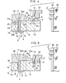
- the apparatus 1 generally comprises a pair of rollers 7, 8 for feeding the rod 4 stepwise upwardly, i.e. in a longitudinal direction indicated by an arrow 9, in regular steps of a distance h ( Figure 2) equal to the thickness of a single coupling element 2', a coacting cutting die and punch 10, 11 for transversely slicing the rod 4 into a plurality of coupling element blanks 2 (only one shown in Figures 3 and 4) in timed relation to the stepwise feeding of the rod 4, and a coacting forming die and punch 12, 13 for forming a slice of coupling element blank 2 into a final coupling element 2'.
- h Figure 2
- the ram 15 has a horizontal channel 17 in which a projection 18 of the cutting .punch 11 is slidably received and which leads to the upper end of the hole 16 of the cutting die 10.
- the cutting die 10 is movable back and forth, in response to the reciprocating movement of the ram 15, across the cutting edge 14 of the cutting punch 11 for transversely slicing the rod 4 into the individual coupling element blanks 2 one on each backward stroke of the movement of the ram 15.
- the apparatus 1 also includes a means, disposed on the projection 18 of the cutting punch 11, for forming a chamfered portion 20 on the base 5 of the rod 4 at the end of each backward stroke of the ram 15, so that each coupling element blank 2 has the chamfereed base 5' ( Figures 3 and 4).
- the chamfered-portion forming means comprises a chamfering surface 21 composed of a pair of first and second beveled surfaces 21a, 21b for being forced against the base 5 of the rod 4 at the end of each backward stroke of the ram 15.
- the chamfered portion 20 on the base 5 of the rod 4 is composed of a pair of third and fourth beveled surfaces 20a, 20b corresponding to the first and second beveled surfaces 21a, 21b on the cutting punch 11.
- the third beveled surface 20a extends at an angle a with respect to a vertical outer side surface 23 of the rod 4
- the second beveled surface 20b extends at an angle (3 with respect to a horizontal upper end surface 4a of the rod 4.
- the chamfering surface 21 is disposed at a corner defined by the projection 18 and a horizontal surface 24.
- the horizontal surface 24 is disposed at a level above the bottom surface 25 of the projection 18 by a distance H ( Figure 2).
- the upper horizontal surface 26 of the cutting die 10, which includes a cutting edge 27, is disposed at a level above the bed 17a of the channel 17 of the ram 15 by the same distance H.
- a chamfered portion is formed on the base of the rod in order that the base of the individual coupling element blank will have had such chamfered portion before the formation of a projection and a coacting socket, and for this reason, it is possible to form a chamfered portion accurately and reliably, thus producing high quality of coupling elements suitable for a two-way slide fastener ( Figure 12).
- the slicing step and the placing step and the chamfered-portion forming step are performed in sequence on only a single stroke of relative movement of the cutting die and punch, it is possible to manufacture accurate coupling elements with improved rate of production.
- Figures 6 through 10 show a modified apparatus 40 according to a second embodiment similar to the apparatus 1 of Figures 1 through 5, and the only difference therefrom is as follows.
- the chamfering surface 21 on the projection 18 of the cutting punch 11 is disposed below a corner 41 (described below) by a distance h ( Figure 7) equal to the thickness of a single coupling element 2', the corner 41 being defined by the projection .18 and the horizontal surface 24.
- the chamfering surface 21 comprises a beveled surface of a nose 42 extending forwardly from the projection 18.
- the forming punch 13 is lowered to press the coupling element blank 2 at the chamfered base 5' to thereby form the latter into a final coupling head 5" ( Figures 7,10,13 and 14) having a projection 30 from the lower face and a coating socket 31 in the upper face at such a position that the beveled surface 20 is disposed around the socket 31.
- the coupling element blank 2 is retained in the recess 28 by the presser 32 lowered together with the forming punch 13.
- a complete coupling element 2' has been produced ( Figures 7 and 10).
- a beveled surface 45 corresponding to the auxiliary chamfering surface 43 is formed on the base 5 of the rod 4.
- the beveled surface 45 is disposed below the beveled surface 20 by the distance h equal to the thickness of one coupling elemeht 2' and hence facilitates the formation of the beveled surface 20 on the next backward stroke of the ram 15.
Landscapes
- Engineering & Computer Science (AREA)
- Mechanical Engineering (AREA)
- Forging (AREA)
- Slide Fasteners (AREA)
Claims (9)
Applications Claiming Priority (4)
| Application Number | Priority Date | Filing Date | Title |
|---|---|---|---|
| JP7200481A JPS57187134A (en) | 1981-05-13 | 1981-05-13 | Molding method and device for tooth for slide fastener |
| JP72004/81 | 1981-05-13 | ||
| JP215060/81 | 1981-12-29 | ||
| JP56215060A JPS58116946A (ja) | 1981-12-29 | 1981-12-29 | スライドフアスナ−用務歯成形装置 |
Publications (3)
| Publication Number | Publication Date |
|---|---|
| EP0064764A2 EP0064764A2 (fr) | 1982-11-17 |
| EP0064764A3 EP0064764A3 (en) | 1983-07-20 |
| EP0064764B1 true EP0064764B1 (fr) | 1985-08-28 |
Family
ID=26413131
Family Applications (1)
| Application Number | Title | Priority Date | Filing Date |
|---|---|---|---|
| EP19820104079 Expired EP0064764B1 (fr) | 1981-05-13 | 1982-05-11 | Procédé et appareil de fabrication des éléments de fermetures à glissière |
Country Status (5)
| Country | Link |
|---|---|
| EP (1) | EP0064764B1 (fr) |
| AU (1) | AU536108B2 (fr) |
| BR (1) | BR8202760A (fr) |
| DE (2) | DE64764T1 (fr) |
| HK (1) | HK62188A (fr) |
Families Citing this family (7)
| Publication number | Priority date | Publication date | Assignee | Title |
|---|---|---|---|---|
| JPH0122505Y2 (fr) * | 1984-09-14 | 1989-07-05 | ||
| JP2803739B2 (ja) * | 1993-01-29 | 1998-09-24 | ワイケイケイ株式会社 | スライドファスナー用務歯および務歯成形方法 |
| JP3355041B2 (ja) * | 1994-08-24 | 2002-12-09 | ワイケイケイ株式会社 | スライドファスナー用務歯とその成形方法及び装置 |
| JP4508909B2 (ja) * | 2005-03-09 | 2010-07-21 | Ykk株式会社 | ファスナーストリンガの連続製造装置 |
| CN101496663B (zh) * | 2008-01-28 | 2011-07-20 | 福建浔兴拉链科技股份有限公司 | 拉链植齿机构及使用该植齿机构的拉链植齿机 |
| ES2666661T3 (es) | 2008-04-14 | 2018-05-07 | Ykk Corporation | Dientes de un lado metálicos y cierre de cremallera bidireccional |
| KR102059847B1 (ko) * | 2016-05-06 | 2019-12-27 | 와이케이케이 가부시끼가이샤 | 파스너 엘리먼트, 파스너 엘리먼트의 제조 장치 및 파스너 엘리먼트의 제조 방법 |
Family Cites Families (4)
| Publication number | Priority date | Publication date | Assignee | Title |
|---|---|---|---|---|
| US2734546A (en) * | 1956-02-14 | Firing | ||
| US2141200A (en) * | 1935-09-03 | 1938-12-27 | Talon Inc | Machine for making fastener stringers |
| US2804677A (en) * | 1950-11-17 | 1957-09-03 | Talon Inc | Machine for making slide fastener stringers |
| US2989803A (en) * | 1957-03-01 | 1961-06-27 | Walter V Chery | Method of making slide fastener elements |
-
1982
- 1982-05-03 AU AU83200/82A patent/AU536108B2/en not_active Ceased
- 1982-05-11 EP EP19820104079 patent/EP0064764B1/fr not_active Expired
- 1982-05-11 DE DE1982104079 patent/DE64764T1/de active Pending
- 1982-05-11 DE DE8282104079T patent/DE3265787D1/de not_active Expired
- 1982-05-13 BR BR8202760A patent/BR8202760A/pt not_active IP Right Cessation
-
1988
- 1988-08-18 HK HK62188A patent/HK62188A/xx unknown
Also Published As
| Publication number | Publication date |
|---|---|
| HK62188A (en) | 1988-08-26 |
| EP0064764A3 (en) | 1983-07-20 |
| DE3265787D1 (en) | 1985-10-03 |
| AU8320082A (en) | 1982-11-18 |
| AU536108B2 (en) | 1984-04-19 |
| BR8202760A (pt) | 1983-04-19 |
| EP0064764A2 (fr) | 1982-11-17 |
| DE64764T1 (de) | 1984-02-02 |
Similar Documents
| Publication | Publication Date | Title |
|---|---|---|
| US4432126A (en) | Method of and apparatus for manufacturing slide fastener coupling elements | |
| EP0608770B1 (fr) | Elément d'accouplement pour une fermeture à glissière et procédé de fabrication | |
| US4163768A (en) | Method of manufacturing molded top stop | |
| US3812573A (en) | Method and apparatus for removing interlocking elements from slide fastener chain | |
| EP0630706B1 (fr) | Méthode et dispositif pour le formage d'un élément d'accouplement pour fermeture à glissière | |
| EP0028358B1 (fr) | Procédé et appareil pour fabriquer des éléments de fermetures à glissières | |
| JP6833829B2 (ja) | ファスナーエレメント、ファスナーエレメントの製造装置、及びファスナーエレメントの製造方法 | |
| CN1084608C (zh) | 拉链链合元件成形装置和剪切冲头 | |
| EP0064764A2 (fr) | Procédé et appareil de fabrication des éléments de fermetures à glissière | |
| GB2028915A (en) | Method of manufacturing separable sliding clasp fasteners | |
| EP0537576B1 (fr) | Curseur pour fermeture à glissière et son procédé de fabrication | |
| US2221740A (en) | Manufacture of slide fastener elements | |
| US4055882A (en) | Method of making a coupling element for a slide fastener | |
| US4010520A (en) | Coupling element for slide fastener | |
| US4349953A (en) | Method of manufacturing slide fastener coupling elements | |
| US2486941A (en) | Method of making slide fastener elements | |
| GB2098889A (en) | Method of and apparatus for manufacturing slide fastener coupling elements | |
| US3446009A (en) | Methods and apparatus for making staples | |
| US2106129A (en) | Method of making separable fasteners | |
| CA2067922C (fr) | Methode de formage de logements creux dans une glissiere de fermeture-eclair | |
| US2490864A (en) | Method of manufacturing interlocking members for sliding clasp fasteners | |
| JPS636295B2 (fr) | ||
| US3171194A (en) | Apparatus and method for manufacturing fasteners | |
| US2543418A (en) | Apparatus for forming and applying bottom stops | |
| CA1156026A (fr) | Methode de fabrication d'elements d'accouplement pour fermetures a glissiere |
Legal Events
| Date | Code | Title | Description |
|---|---|---|---|
| PUAI | Public reference made under article 153(3) epc to a published international application that has entered the european phase |
Free format text: ORIGINAL CODE: 0009012 |
|
| AK | Designated contracting states |
Designated state(s): BE DE FR IT NL |
|
| PUAL | Search report despatched |
Free format text: ORIGINAL CODE: 0009013 |
|
| AK | Designated contracting states |
Designated state(s): BE DE FR IT NL |
|
| 17P | Request for examination filed |
Effective date: 19830930 |
|
| ITCL | It: translation for ep claims filed |
Representative=s name: JACOBACCI CASETTA & PERANI S.P.A. |
|
| EL | Fr: translation of claims filed | ||
| TCNL | Nl: translation of patent claims filed | ||
| DET | De: translation of patent claims | ||
| ITF | It: translation for a ep patent filed | ||
| GRAA | (expected) grant |
Free format text: ORIGINAL CODE: 0009210 |
|
| AK | Designated contracting states |
Designated state(s): BE DE FR IT NL |
|
| REF | Corresponds to: |
Ref document number: 3265787 Country of ref document: DE Date of ref document: 19851003 |
|
| ET | Fr: translation filed | ||
| PLBE | No opposition filed within time limit |
Free format text: ORIGINAL CODE: 0009261 |
|
| STAA | Information on the status of an ep patent application or granted ep patent |
Free format text: STATUS: NO OPPOSITION FILED WITHIN TIME LIMIT |
|
| 26N | No opposition filed | ||
| ITTA | It: last paid annual fee | ||
| PGFP | Annual fee paid to national office [announced via postgrant information from national office to epo] |
Ref country code: FR Payment date: 19940420 Year of fee payment: 13 |
|
| PGFP | Annual fee paid to national office [announced via postgrant information from national office to epo] |
Ref country code: NL Payment date: 19940531 Year of fee payment: 13 Ref country code: DE Payment date: 19940531 Year of fee payment: 13 |
|
| ITPR | It: changes in ownership of a european patent |
Owner name: CAMBIO RAGIONE SOCIALE;YKK CORPORATION |
|
| PG25 | Lapsed in a contracting state [announced via postgrant information from national office to epo] |
Ref country code: NL Effective date: 19951201 |
|
| NLV4 | Nl: lapsed or anulled due to non-payment of the annual fee |
Effective date: 19951201 |
|
| PG25 | Lapsed in a contracting state [announced via postgrant information from national office to epo] |
Ref country code: DE Effective date: 19960201 |
|
| PG25 | Lapsed in a contracting state [announced via postgrant information from national office to epo] |
Ref country code: FR Effective date: 19960229 |
|
| REG | Reference to a national code |
Ref country code: FR Ref legal event code: ST |
|
| REG | Reference to a national code |
Ref country code: FR Ref legal event code: ST |
|
| PGFP | Annual fee paid to national office [announced via postgrant information from national office to epo] |
Ref country code: BE Payment date: 20010227 Year of fee payment: 20 |
|
| BE20 | Be: patent expired |
Free format text: 20020511 *YKK CORP. |