EP0064807A2 - Profiländerungsfühler - Google Patents
Profiländerungsfühler Download PDFInfo
- Publication number
- EP0064807A2 EP0064807A2 EP82301582A EP82301582A EP0064807A2 EP 0064807 A2 EP0064807 A2 EP 0064807A2 EP 82301582 A EP82301582 A EP 82301582A EP 82301582 A EP82301582 A EP 82301582A EP 0064807 A2 EP0064807 A2 EP 0064807A2
- Authority
- EP
- European Patent Office
- Prior art keywords
- signal
- sensor according
- light
- conveying
- signal path
- Prior art date
- Legal status (The legal status is an assumption and is not a legal conclusion. Google has not performed a legal analysis and makes no representation as to the accuracy of the status listed.)
- Withdrawn
Links
Images




Classifications
-
- G—PHYSICS
- G01—MEASURING; TESTING
- G01L—MEASURING FORCE, STRESS, TORQUE, WORK, MECHANICAL POWER, MECHANICAL EFFICIENCY, OR FLUID PRESSURE
- G01L19/00—Details of, or accessories for, apparatus for measuring steady or quasi-steady pressure of a fluent medium insofar as such details or accessories are not special to particular types of pressure gauges
- G01L19/08—Means for indicating or recording, e.g. for remote indication
- G01L19/12—Alarms or signals
Definitions
- This invention relates to profile change sensors and is especially concerned with low energy profile change sensors.
- a “profile change sensor” means for sensing a change in the shape or relate position or both of at least one surface, or a part thereof, of a body.
- a “low energy profile change sensor” is meant a profile change sensor as above defined in which the energy dissipated in the sensor when in operation is such that the danger of any inflammable material in the neighbourhood of the sensor being ignited as a result of the operation of the sensor is small to non-existent.
- the inflammable material may comprise inflammable fluids (gases, liquids or vapours) either on their own or mixed with solid particles.
- Inflammable mixtures of fluids and solids in the neighbourhood of the body may also comprise inherently non-flammable fluids and inflammable solids or fluids and solids both of which are inherently non-flammable but which together form an inflammable mixture.
- the invention is particularly, hut not exclusively, concerned with means for detecting the failure of bursting discs. At least one embodiment of the invention may also be used for the detection of the creep of bursting discs and of the lifting and/or chattering of pressure relief valves. Bursting discs are also known, inter alia, as “rupture discs”, “safety discs” and “frangible discs”.
- a known way of detecting the creep of a conventional bursting disc that is, one in which pressure is applied to the concave surface of the dome of the disc, is to shine a beam of light from one side to the other of the pipe in which the bursting disc is located, the light being arranged to fall on a slit in front of a photocell and the slit being so positioned that the ribbon of light passing through it just grazes or passes close to the topmost region of the convex surface of the dome of the disc. If the disc creeps, then the light beam will be progressively interrupted and the signal from the photocell will change and this change can be made to operate an alarm or indicator system.
- a conventional disc could burst or rupture in such a way that one or more flaps of dome material could obscure the slit and/or the light source and thus prevent light from the source from reaching the photocell so that the indicator or alarm system would not be triggered.
- Another disadvantage is that different arrangements are required to detect on the one hand the creep of a conventional disc and on the other hand, the rupture or failure thereof.
- testing arrangements can also be used in the detection of the lifting and chattering of pressure relief valves.
- the present invention aims to provide reliable means for detecting, inter alia, changes in the condition of bursting discs such as their creep and/or failure and changes in the condition of pressure relief valves such as their lifting and/or chattering in which the disadvantages of conventional arrangements, such as those described above, are obviated.
- a profile change sensor (as herein defined) comprises a source of energy, at least one signal conveying member for establishing a signal path from the source of energy to a signal responsive member with the signal conveying member or a further member associated therewith so disposed in relation to at least a part of a surface of a body that in the event of a change, greater than a given magnitude and in a given direction of the position or the shape of the said part of the body or both, occurrence of the change results in the interruption or the establishment of a signal:
- the body is preferably a bursting disc or a pressure relief valve. If desired:-
- one or more light guides are employed.
- light guides 1 and 2 are shown passing through pressure seal 3 in the wall of a collar 4, which constitutes the upper holder flange of a bursting disc assembly incorporating a conventional bursting disc.
- the light guides rest on the dome, represented by the broken line 5, of the bursting disc and at their opposite ends enter a cavity 6 in the wall of the collar 4 via small holes in a flexible diaphragm 7, secured across the entrance to the cavity.
- those portions of the light guides which rest on the dome and pass through the flexible diaphragm 7 are circumferentially coated with a plastics material.
- the cavity 6 is preferably substantially hemispherical in form and the curved wall 8 is preferably provided with a reflective coating.
- the inner surface of the flexible diaphragm is also made reflective.
- FIG. 9 represents a light-emitting diode which is connected to a source of electrical energy via the wires 11 and which feeds light into the end of the light guide 1.
- Item 10 is a photo-responsive device which receives and responds to light which has emerged from the opposite end of light-guide 1, and then after reflection by the surface 8 of cavity 6 and the inner surface of diaphragm 7 has entered the other light guide 2 and passed thence along this light guide to its opposite end.
- one or other of the light guides will be pulled out of the diaphragm 7 and/or broken much more rapidly than in the previous case but the result will be the same and an alarm or indicator may, for example, be activated.
- the collar 4 which is not to scale, forms one of a pair of so-called “holder flanges” between which the flange or clamping face 13 of the bursting disc is clamped to form a bursting disc assembly.
- the two holder flanges are commonly held together and clamped on to the flange 13 of the bursting disc by means of so-called “Allen”, “cap-head” or “socket” screws which pass through one holder flange into the other in a direction substantially parallel to their common axis of symmetry.
- FIG. 1 A part-diagrammatic view of the collar 4 is also given in Figure 2.
- the light guides 1 and 2 on emerging from the pressure seal 3 pass into an adaptor unit 14.
- This is designed to receive, inter alia, the mating portion 15 of a hand held, battery-powered test unit 16.
- This may comprise an LED 17 and a photo-sensitive device 18, each being connected via light guides 19 and 20 to mating portion 15 of unit 16.
- portion 15 is plugged into the mating cavity 20 of unit 14 so that the ends of light guides 1 and 2 are in optical contact with the ends of light guides 19 and 20 respectively.
- LED 17 is then switched on and, if both of the light guides 1 and 2 are intact with their ends passing through diaphragm 7 as shown, light from the LED 17 will pass into the photo-responsive device via light guides 19, 1, 2 and 20 and the resulting output from the device 18 will be registered by some suitable indicating instrument- (not shown) forming part of the unit 16.
- the indication of an output from device 18 then shows the operator that the light guides 1 and 2 are undisturbed and the bursting disc (5 in Figure 1) accordingly intact.
- the end of the light guide may be presented to an eye-piece in the wall of unit 16. On viewing the end of the light guide through the eye-piece the operator will see the end of the light guide lit up if guides 1 and 2 are not disturbed sufficiently to pull one or the other out of diaphragm 7 and the end of the light guide dark if guides 1 and 2 are so disturbed and/or are broken.
- the light- guides 1, 2 on emerging from pressure seal 3 could be extended to a central control point where the state of the light guides 1, 2 within collar 4, and hence the condition of the bursting disc, could either be continuously monitored or checked regularly according to a preset programme and/or checked at will by means of a device of the type indicated at 16 in Figure 2.
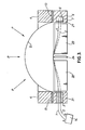
- FIG 3 the flange or clamping face 13 of a reverse bursting disc is shown clamped between collars or holding flanges 4 and 21.
- a bursting disc of this type is, in use, subjected to pressure on the convex surface of the dome 5 as shown by the arrows P. When this pressure exceeds the design pressure (or a value in the region thereof) the dome collapses inwardly on to a cruciform array of knives which cut the material of the disc into four sector-shaped pieces and thereby ensure an unhindered release of the pressure. Three of these knives are shown as items 22, 23 and 24 in Figure 3.
- flange 21 in Figure 3 is provided with a pressure seal 3 through which pass light guides 1 and 2 in a gas-tight manner.
- the guides 1, 2 pass, respectively, over the knife 24 and the knife (not shown) behind it which forms the fourth arm of the cross, the light guide 2 where it passes behind knives 22 and 23 being shown by the broken line.
- the light guides pass through the flexible diaphragm 7 which is fitted across the opening of cavity 8.
- the walls of this cavity are reflective as is, preferably, the inner surface of the diaphragm 7.
- the bursting disc assembly shown in Figure 3 may be used in essentially the same way as described with reference to Figure 2, adaptor box 14 being provided with the same facilities as adaptor box 14 in the arrangements shown in Figure 2.
- the pressure tight seal 3 in the arrangements shown in Figures 1, 2 and 3 may comprise a filling of plastics material in a suitably shaped hole passing through the wall of the holder flange 4 or 21, the two light guides passing through the plasticsmaterial.
- it is a threaded plasticsstopper which screws into a tapped hole in the wall of the holder flange and which may be provided with one or more 0-ring seals to ensure that the joint is gas-tight.
- Such an arrangement has the advantage that a holder flange may easily be provided with a replacement unit comprising an adaptor and light guides when a disc has burst and the bursting disc assembly is being remade.
- the light guide would, for example, pass through a holder flange wall via a seal such as 3 and then again pass through a flexible diaphragm covering the entrance to a chamber approximately diametrically opposed to the seal.
- the chamber in this case would be smaller than before and would be so arranged that the end of the light guide would come into optical contact with a further light guide passing through a gas-tight seal in the remainder of the wall of the holder flange to suitable means for detecting the emission of light from the end of this said further light guide.
- optical contact both here and elsewhere in this specification is meant that the ends of the two light guides are so disposed in relation to each other, with or without an interposed zone of some plastics material, for example, of similar refractive index to the material of the light guides, that at least a proportion of any light emerging from the end of one light guide will enter the end of the other light guide.
- some plastics material for example, of similar refractive index to the material of the light guides
- the two light guides may be replaced by a single light guide and pulse techniques used for determining the continuity or otherwise of the optical path.
- the light will be passed into the light guide in short pulses and the reception of the reflected light back along the light guide detected by sophisticated measuring techniques.
- bursting discs are normally supplied in assemblies each comprising a disc and two holder flanges as shown in Figure 3. Such assemblies are normally clamped in a gas-tight manner between pipe flanges and provide positive and predictable relief of pressure in a vessel or pipe line when the pressure exceeds a predetermined value.
- the invention has been described above with reference to the monitoring of the condition of bursting discs by means of light guides, it is by no means so limited.
- other signal-conveying means could be used and also, both these and light guides could be used to provide a warning if, say, part of a pressure relieve valve should lift or begin to chatter or if part of a machine tool or some other equipment, such as an overhead crane, should move beyond a predetermined position.
- the invention could be used as a burglar or intruder alarm to detect, for example, the opening of a door or the movement of a fence.
- the invention could be used to determine when fluid begins to flow along a pipe or when the rate of flow of such a fluid along a pipe increases. This could be done, for example, by replacing part of the pipe wall with a flexible diaphragm and using the methods of the invention to sense any disturbance, greater than a certain magnitude, of the diaphragm surface resulting from the fluid beginning to flow along the pipe or from an increase in its rate of flow along the pipe.
- two signal conveying members such as light guides might be stretched across the pipe in accordance with the methods of the invention, with a "body” comprising a web of some suitable material such as "FEP" (fluorinated ethylene propylene) between them. Any flow of fluid along the pipe at a velocity higher than a certain threshold value would then move the body so as to cause at least one signal conveying member to be disconnected and the associated signal path to be interrupted.
- FEP fluorinated ethylene propylene
- the adaptor box 14 used in this arrangement may be provided with the same facilities as the adaptor box 14 of Figure 2.
- the adaptor 14 may be used to correct the two ends of light guide 25 to a central control point where the state of the limbs 26, 28 and 30 could be either continuously monitored or checked regularly according to a pre-set programme as previously described.
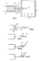
- Figure 7 shows a part of the pipe 32 in which an umbrella-like member 33 is mounted of shock waves which would result from rupture of the bursting disc 5 not shown but disposed downstream of the umbrella member 33.
- the housing is, in turn, supported on the wall of pipe 32.
- Two light guides 36 (input) 37 (output) are located in the housing 35 as shown and, depending upon the position of the arm 34, the aperture 34A will or will not be in alignment with arms 36A, 37A of the light guides 36 and 37 respectively.
- the arms 36A, 37A are in alignment with the aperture 34A light may pass from arm 36A to 37A through the apertures 34A (see Figure 8). In a position of non-alignment, light cannot pass between the two light guides 36 and 37.
- FIGs 7,8 and 9 show the arrangement with the umbrella member 33 in an "undisturbed' position so light can pass from arm 36A to arm 37A unhindered.
- a shock wave passes along the pipe 32 in the direction of the arrows 38 and impinges on the umbrella-member 33 causing the same to pivot as shown in Figures 10 and 11.
- Such pivot movement of the umbrella member 33 causes the arm 34 to move to the right in Figure so that the aperture 34A is displaced out of alignment with the arms 36A, 37A.
- any light signal previously transmitted between is interrupted indicating pivotal displacement of the umbrella member 33 consequent upon the rupture of the bursting disc 5.
- the interruption of the light signal can be made to actuate an alarm signal.
- the arrangement may operate so that in the rest position light is prevented from travelling from arm 36A to arm 37A since the aperture 34A is out of alignment with these two arms.
- the aperture elongated if necessary
- the arrangement may operate so that in the rest position light is prevented from travelling from arm 36A to arm 37A since the aperture 34A is out of alignment with these two arms.
- Figure 12 is a modification of the arrangement of Figures 7 to 11 in which the arm 34 is replaced by a tubular member 39 with a bell-mouthed end 40 disposed towards the bursting disc 5 (not shown).
- piston-like plug 41 having an aperture 42 is displaceble within the tube39.
- the piston-like plug 41 is displaced to the left in the Figure and movement is restrained by a perforated or other stop 43.
- the aperture 42 is displaced out of alignment with arms 36A, 37A of 'the light guides 36 and 37 so that any signal between these arms is interrupted.
- the aperture 42 maybe brought into, alignment with the said arms when the piston 41 is in the displaced and restrained position thereby permitting a signal to pass between arms 36A and 37A.
- a single and continuous light guide is mounted in the housing 35 and extends into the pipe 32 at 44. At least that part 44 of the light guide is brittle so that impingment thereon by a shock wave. 38 or a portion of a ruptured bursting disc causes fracture thereof and the interruption of a light signal along the guide 25.
- the arrangement of Figure 13 is turned through 90° so that the arms or part 44 are located in a plane at' right angles to the plane of the Figure as' shown in Figure 14.
- Figure 14 shows a modification of Figure 13 in which an umbrella member 45 is secured to the arms 44.
- the umbrella member 45 may be replaced by one or more turns of a strip of plastics or other material wound around the legs of part 4
- Figure 15 shows yet a further arrangement according to the invention in which the housing 25 is generally cylincrical having a tabular end 46 defining a cylindrical cavity 47.
- a disc 46 is pivotally mounted to close the cavity 47 and on one face thereof causes a concave reflecting body 49 and on the other face an umbrella member 50.
- an annular array of input light guides 36 conveys light to the reflecting body 49 from whence the light is focussed onto a central outlet light guide 37.
- the underlying principle of a displaceable reflecting body such as the disc 48 of Figure 15 represents a feature of the present invention and may be realised in a number ofdifferent ways of which the arrangement of Figure 15 represents only one.
- the arrangement of Figure 15 may be modified so that the right hand ends of the light guides terminate in a plane which is inclined relatively to the axis of the pipe 32.
- a flat reflecting body is disposed in a plane parallel to the plane containing the ends of the light guides so that it reflects input light signals into one or more output light guides.
- a portion of the flat reflecting body extends into the path of a shock wave represented by arrows 38 so that upon the rupture of a bursting disc, the flat reflecting body is displaced so that signals are interrupted.
- This underlying principle is shown in Figure 16.
- the light guides referred to in all of the foregoing may take the form of optical fibres.
- sonic signals may be passed through or along sonic energy conveying members or, yet again, low voltage electrical signals may be passed along electrical conducting members.
Landscapes
- Physics & Mathematics (AREA)
- General Physics & Mathematics (AREA)
- Measuring Fluid Pressure (AREA)
- Control Of Conveyors (AREA)
- Optical Transform (AREA)
- Length Measuring Devices By Optical Means (AREA)
- Length Measuring Devices With Unspecified Measuring Means (AREA)
- Arrangements For Transmission Of Measured Signals (AREA)
Applications Claiming Priority (2)
| Application Number | Priority Date | Filing Date | Title |
|---|---|---|---|
| GB8109455 | 1981-03-26 | ||
| GB8109455 | 1981-03-26 |
Publications (2)
| Publication Number | Publication Date |
|---|---|
| EP0064807A2 true EP0064807A2 (de) | 1982-11-17 |
| EP0064807A3 EP0064807A3 (de) | 1983-01-05 |
Family
ID=10520669
Family Applications (1)
| Application Number | Title | Priority Date | Filing Date |
|---|---|---|---|
| EP82301582A Withdrawn EP0064807A3 (de) | 1981-03-26 | 1982-03-25 | Profiländerungsfühler |
Country Status (4)
| Country | Link |
|---|---|
| EP (1) | EP0064807A3 (de) |
| JP (1) | JPS57211002A (de) |
| ES (1) | ES8308118A1 (de) |
| ZA (1) | ZA822066B (de) |
Cited By (3)
| Publication number | Priority date | Publication date | Assignee | Title |
|---|---|---|---|---|
| EP2784363A1 (de) * | 2009-07-31 | 2014-10-01 | BS & B Safety Systems Limited | Integritätssensor für Druckentlastungsvorrichtung |
| CN113544483A (zh) * | 2019-03-12 | 2021-10-22 | 横滨橡胶株式会社 | 船舶用软管的流体泄漏感测仪 |
| CN115899339A (zh) * | 2023-03-10 | 2023-04-04 | 成都凯天电子股份有限公司 | 一种反拱型光纤爆破片 |
Family Cites Families (3)
| Publication number | Priority date | Publication date | Assignee | Title |
|---|---|---|---|---|
| FR1493432A (fr) * | 1965-12-22 | 1967-09-01 | Dispositif capteur de pression ou de vibrations | |
| US4232698A (en) * | 1978-09-28 | 1980-11-11 | Products Of Advanced Technology, Inc. | Pressure relief valve with pressure indicating means |
| US4342988A (en) * | 1980-01-25 | 1982-08-03 | Continental Disc Corporation | Rupture disc alarm system |
-
1982
- 1982-03-25 EP EP82301582A patent/EP0064807A3/de not_active Withdrawn
- 1982-03-26 ZA ZA822066A patent/ZA822066B/xx unknown
- 1982-03-26 ES ES510848A patent/ES8308118A1/es not_active Expired
- 1982-03-26 JP JP57047509A patent/JPS57211002A/ja active Pending
Cited By (6)
| Publication number | Priority date | Publication date | Assignee | Title |
|---|---|---|---|---|
| EP2784363A1 (de) * | 2009-07-31 | 2014-10-01 | BS & B Safety Systems Limited | Integritätssensor für Druckentlastungsvorrichtung |
| US10139005B2 (en) | 2009-07-31 | 2018-11-27 | Bs&B Safety Systems Limited | Pressure relief device integrity sensor |
| CN113544483A (zh) * | 2019-03-12 | 2021-10-22 | 横滨橡胶株式会社 | 船舶用软管的流体泄漏感测仪 |
| EP3940363A4 (de) * | 2019-03-12 | 2022-05-18 | The Yokohama Rubber Co., Ltd. | Flüssigkeitsleckdetektor für meeresschlauch |
| CN115899339A (zh) * | 2023-03-10 | 2023-04-04 | 成都凯天电子股份有限公司 | 一种反拱型光纤爆破片 |
| CN115899339B (zh) * | 2023-03-10 | 2023-05-26 | 成都凯天电子股份有限公司 | 一种反拱型光纤爆破片 |
Also Published As
| Publication number | Publication date |
|---|---|
| ES510848A0 (es) | 1983-08-01 |
| ES8308118A1 (es) | 1983-08-01 |
| JPS57211002A (en) | 1982-12-24 |
| EP0064807A3 (de) | 1983-01-05 |
| ZA822066B (en) | 1983-03-30 |
Similar Documents
| Publication | Publication Date | Title |
|---|---|---|
| EP0033867B1 (de) | Alarmsystem mit Berstscheibe | |
| US4464936A (en) | Monitoring apparatus for pressure sensitive devices | |
| US4354180A (en) | Electro-optical liquid level sensor | |
| US4516022A (en) | Detection of light-producing events | |
| US5193129A (en) | Pressure sensor utilizing microbending of a fiber optic cable woven through a ladder shaped structure | |
| US5343736A (en) | Optical leak sensor and position detector | |
| WO2001047772A1 (en) | Icing detector for aircraft | |
| CA2769452C (en) | Pressure relief device integrity sensor | |
| USRE34308E (en) | Rupture disc alarm system | |
| US4882576A (en) | Remote combustible gas sensor | |
| US3952196A (en) | Radiation detection apparatus | |
| EP0962685B1 (de) | Ventilanordnung | |
| GB2095825A (en) | Profile change sensor | |
| EP0064807A2 (de) | Profiländerungsfühler | |
| CA1298379C (en) | Movement detector with mercury switch | |
| EP0092323A1 (de) | Anzeigeeinrichtung mit einer berstenden Scheibe | |
| US3785440A (en) | Pressure monitor and transducer | |
| US5748090A (en) | Optical flameout detector | |
| US4712096A (en) | Condition responsive detection system and method | |
| WO1999064841A9 (en) | Backscatter instrument for monitoring particulate levels in a gas stream | |
| US4677426A (en) | Dust detecting ring assembly | |
| CN218825798U (zh) | 全自动油气管道应力监测系统 | |
| EP3306764A1 (de) | Sensoranordnung zur optischen lichtbogenerkennung | |
| GB1389273A (en) | Pulse reflection test means for pressure surveillance detector | |
| US4609817A (en) | Optical shaft position sensor |
Legal Events
| Date | Code | Title | Description |
|---|---|---|---|
| PUAI | Public reference made under article 153(3) epc to a published international application that has entered the european phase |
Free format text: ORIGINAL CODE: 0009012 |
|
| PUAL | Search report despatched |
Free format text: ORIGINAL CODE: 0009013 |
|
| AK | Designated contracting states |
Designated state(s): AT BE CH DE FR GB IT NL SE |
|
| AK | Designated contracting states |
Designated state(s): AT BE CH DE FR GB IT LI NL SE |
|
| 17P | Request for examination filed |
Effective date: 19830616 |
|
| STAA | Information on the status of an ep patent application or granted ep patent |
Free format text: STATUS: THE APPLICATION IS DEEMED TO BE WITHDRAWN |
|
| 18D | Application deemed to be withdrawn |
Effective date: 19841031 |
|
| RIN1 | Information on inventor provided before grant (corrected) |
Inventor name: TAYLOR, WILLIAM NICHOLAS HOWARD Inventor name: POTTER, RICHARD ALAN Inventor name: HEYWOOD, ALAN EDWARD Inventor name: BENEDEK, ROBIN ANDRAS Inventor name: FLEET, KENNETH JOHN Inventor name: SMITH, ALAN WILFRED Inventor name: BARREL, JOHN DOUGLAS |