EP0064836A2 - Ventilantrieb für eine Kolbenbrennkraftmaschine - Google Patents
Ventilantrieb für eine Kolbenbrennkraftmaschine Download PDFInfo
- Publication number
- EP0064836A2 EP0064836A2 EP82302176A EP82302176A EP0064836A2 EP 0064836 A2 EP0064836 A2 EP 0064836A2 EP 82302176 A EP82302176 A EP 82302176A EP 82302176 A EP82302176 A EP 82302176A EP 0064836 A2 EP0064836 A2 EP 0064836A2
- Authority
- EP
- European Patent Office
- Prior art keywords
- rocker arm
- pin
- fulcrum
- valve
- contact
- Prior art date
- Legal status (The legal status is an assumption and is not a legal conclusion. Google has not performed a legal analysis and makes no representation as to the accuracy of the status listed.)
- Granted
Links
Images


Classifications
-
- F—MECHANICAL ENGINEERING; LIGHTING; HEATING; WEAPONS; BLASTING
- F01—MACHINES OR ENGINES IN GENERAL; ENGINE PLANTS IN GENERAL; STEAM ENGINES
- F01L—CYCLICALLY OPERATING VALVES FOR MACHINES OR ENGINES
- F01L1/00—Valve-gear or valve arrangements, e.g. lift-valve gear
- F01L1/12—Transmitting gear between valve drive and valve
- F01L1/18—Rocking arms or levers
- F01L1/181—Centre pivot rocking arms
- F01L1/182—Centre pivot rocking arms the rocking arm being pivoted about an individual fulcrum, i.e. not about a common shaft
- F01L1/183—Centre pivot rocking arms the rocking arm being pivoted about an individual fulcrum, i.e. not about a common shaft of the boat type
Definitions
- This invention relates to valve trains for internal combustion engines and, in particular, to a rocker arm and pivot assembly for use in such valve trains.
- rocker arm and pivot assemblies as normally used in passenger vehicle type engine valve trains, for example, as used in an overhead valve push-rod type actuated valve train, include a pedestal mounted rocker arm which generally has a spherical or part cylindrical pivot or fulcrum that provide essentially large bearing surfaces. With such an arrangement, the rocker arm is actually in sliding engagement relative to its associate fulcrum and, thus even though these elements may be adequately lubricated, this type arrangement still provides a large area for frictional resistance so as to produce a heat build-up as a result of the loads being applied to the respective bearing surfaces.
- rocker arm and its associate pivot assembly which includes one or more roller bearing assemblies is far more complex and expensive, from a production standpoint, to use in conventional passenger vehicle engines.
- rocker arm and pivot arrangement such that the rocker arm is claimed to be movable about a support in rolling motion in a manner shown, for example, in United States patent 2,943,612 entitled Valve Gear which issued on July 5, 1960 to Alexander G. Middler as an improvement over the rocker arm pivot structure shown in United States patent 1,497,451 entitled Rocker Arm issued June 10, 1924 to John F. Kytlica.
- a valve train means in a reciprocating internal combustion engine of the type having an engine block defining a cylinder with a port, a valve reciprocably located in said port and biased to a predetermined position, and a valve actuator spaced from the valve and movable in opposite sense to reciprocate the same, said valve train means including a rocker arm in engagement with the valve and the valve actuator and actuated in rocking movement to reciprocate said valve against said bias to open and close the port for engine operation, is characterised in that said valve train means includes:
- a primary object of the present invention is to provide an improved rocker arm and pivot assembly wherein an otherwise conventional type rocker arm and its fixed fulcrum are provided with part circular concave and convex bearing surfaces having preferably a radius relationship of substantially R and one-half R, respectively, with these elements being provided with a retainer pin and slot arrangement whereby there is effected a substantially rolling or walking contact between all parts relative to each other during pivotable movement of the rocker arm.
- another object of this invention is.to provide an improved rocker arm and pivot assembly having a rocker arm with a semi-cylindrical bearing surface intermediate its ends and its associated pivot having a semi-cylindrical fulcrum bearing surface, the ratio of the radii of this surface being of the order of 3:1 to 1.7:1 and preferably 2:1.
- One of the bearing surfaces is provided with a guide recess or slot therein of a size and shape so as to receive in substantially rolling or walking contact a raised retainer pin provided on the other bearing surface, the slot and retainer pin preferably being located intermediate the arcuate ends of the respective bearing surface.
- Still another object of this invention is to provide an improved rocker arm and pivot assembly for use in the valve trains of internal combustion engines which, in operation, is characterised by minimum energy loss to thus maximize fuel efficiency.
- Still another object of the present invention is to provide a rocker arm and pivot of the above type which is easy and inexpensive to manufacture, which is reliable in operation, and in other respects suitable for use on production motor vehicle engines.
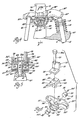
- Figure 1 a portion of an internal combustion engine, of the conventional overhead valve type, having a cylinder head 10. Slidably guided for axial reciprocation in a guide bore 11 of the cylinder head 10 is the stem of a poppet valve 12, the upper portion of which projects above the cylinder head.
- the poppet valve 12 is normally maintained in a closed position by a spring 14 encircling the upper portion of the stem of the valve 12, with one end of the spring 14 engaging the cylinder head 10 and the other end engaging a conventional retaining washer assembly 15 secured to the stem of the poppet valve 12 in a conventional manner.
- a push rod 16 which is reciprocably disposed in the cylinder head laterally of the poppet valve 12, has its upper end projecting above the cylinder head 10. As would be conventional, the lower end of the push rod 16 abuts against the upper end of a valve tappet, not shown, which operatively engages the cam of a camshaft, not shown, in a conventional manner whereby the push rod is caused to reciprocate, as determined by the profile of the cam on the camshaft, not shown.
- a valve rocker arm Operatively connecting the push rod 16 and the poppet valve 12 is a valve rocker arm, generally designated 20, constructed in accordance with the invention.
- the arm 21, on its bottom surface is spherically dished at 23 so as to socketably receive the upper end of the push rod 16.
- the rocker arm is provided with an intermediate curved portion 24 provided with an upper, semi-cylindrical, concave bearing surface 25.
- the rocker arm 20 is substantially U-shaped in section with a web portion formed by the arms 21 and 22 and the intermediate portion 24, and it is provided with integral upstanding side walls 26 and end walls 27a and 27b.
- the bearing surface 25 is adapted to cooperate in a manner to be described hereinafter with a fixed apertured pivot support or fulcrum 40 having a lower semi-cylindrical concave bearing surface 41 to be described in detail hereinafter.
- the rocker arm 20, intermediate its ends and centrally of its intermediate portion 24, is provided with a longitudinally extending aperture 28, as best seen in Figure 3, through which there extends a suitable support member, herein shown as stud 50, that is suitably secured to the cylindrical head 10 and which is provided at its free upper end with external threads 51 to threadingly receive a threaded nut 52 used to retain the fulcrum 40.
- a suitable support member herein shown as stud 50
- the fulcrum 40 in the embodiment illustrated is of rectangular configuration and is of longitudinal extent whereby it can be loosely received between the side walls 26 of the rocker arm 20.
- the fulcrum 40 is provided with a flat upper surface 42 for abutment against the underside of nut 52 and it is provided with a central through aperture 43 of a suitable diameter whereby to slidably receive the stud 50 therethrough.
- the bearing surface 25 of the rocker arm 20 is formed with a suitable predetermined radius R, while the bearing surface 41 of fulcrum 40 is formed with substantially a radius 1/2 R, so that during pivotal movement of the rocker arm (0, the bearing surface 41 of fulcrum 40 will be in rolling contact with the bearing surface 25 of rocker arm 20.
- the relative rolling contact between these bearing surfaces having a radii ratio of 2:1 may be referred to as cardanic motion.
- Cardanic motion is the plane motion of a circle or cylinder rolling inside another circle or cylinder, respectively, twice its size without slippage at the contact point between these elements.
- the cardanic motion is obtained by having the radii of curvature of these fixed and moving centrodes in the ratio of 2:1, with the centrodes lying on the same side of a common tangent.
- a point on the circumference of the rolling circle or cylinder will be in a straight line extending through the axis of the rolling circle or cylinder.
- the fulcrum 40 is provided with a raised retainer pin 44 depending from and preferably located intermediate the ends of the bearing surface 41.
- the retainer pin 44 thus extends longitudinally outward a predetermined distance from opposite sides of the aperture 43 and in alignment with and at right angles to the axis of this vertical aperture 43.
- the retainer pin is symmetrically located with respect to the axis of stud 50.
- the raised retainer pin 44 which is shaped similar to a gear tooth and is of suitable thickness to withstand any side loading thereon to be encountered in a given engine application, is slidably received in a through tapered recess or guide slot 29 provided in the intermediate portion 24 of the rocker arm 20.
- guide slot 29 is also preferably located intermediate the ends of the bearing surface 25 so as to extend transversely outboard of the aperture 28 in alignment with and at right angles to the central vertical axis of this aperture.
- guide slot 29 is preselected relative to the width of pin retainer 44, whereby the retainer pin 44 will be slidably received in the slot 29 so that it will be operative to ensure the rolling contact of bearing surface 41 relative to the bearing surface 25 of the rocker arm 20. It will also be apparent that this retainer pin 44 and guide slot 29 arrangement will be operative so as to prevent lateral pivotal movement of the rocker arm at right angles to its plane of intended pivotal movement in response to reciprocation of the push rod 16. A preferred guide slot 29 and cooperating retainer pin 44 configuration is described in detail hereinafter.
- Rocker arm 20' in this alternate embodiment, is also provided with arms 21' and 22' and an intermediate portion 24'.
- the rocker arm is substantially U-shaped in a transverse cross-section with a web portion defined by the arms 21' and 22' and the intermediate portion 24' and with integral upstanding side walls 26'.
- rocker arm 20' intermediate its ends and centrally of the intermediate portion 24', is provided with a longitudinally extending through aperture 28'.
- the rocker arm 20' is provided with a transversely extending rocker means which defines a cylindrical bearing surface means 30.
- the cylindrical bearing means 30 has a retainer pin means 44' extending radially outward therefrom.
- each rocker pin 31 is defined by a pair of transversely spaced apart rocker pins 31 formed as separate elements which are suitably secured to the rocker arm 20', with each rocker pin 31 having a retainer pin 44', also formed as separate elements, suitably fixed thereto.
- each rocker pin 31 is provided with an axially extending slot 32 in the outer peripheral surface thereof and extending a predetermined extent from one end thereof and of a configuration so as to receive the foot end of a retainer pin 44' which is then fixed, as by welding, to the rocker pin.
- each side wall 26' is provided with a key-shaped aperture therethrough that is aligned with and formed at right angles to the axis of the aperture 28' and which defines a circular aperture 33 of a size to slidably receive an associated rocker pin 31 and a slot aperture 34 of a size and shape to receive the exposed portion of the associated retainer pin 44'.
- each rocker pin 31 and associated retainer pin 44' is inserted into an associated side wall 26' so that the retainer pin 44' is located at the outboard end of its rocker pin 31 as thus partly trapped within the associated side wall 26'.
- the rocker pin 31 and associated retainer pin 44' can then be further fixed to the rocker arm 20', for example, as by welding at the interface of these elements with the associated side wall 26'.
- a fulcrum post 60 Associated with the rocker arm is a fulcrum post 60, of T-shaped configuration, as best seen in Figures 5 and 6, having a vertically extending post 61 portion with fulcrum arms 62 extending outward from opposite sides thereof and at right angles thereto, the combined extent of which is such that these fulcrum arms will be slidably received between the side walls 26' of the rocker arm 20'.
- the post 61 is suitably sized so that it can loosely extend through the aperture 28' in rocker arm 20'.
- Each fulcrum arm 62 on its lower face is provided with a concave, semi-cylindrical bearing surface 63 for relative rolling engagement with the bearing surface means 30 of rocker pins 31.
- each fulcrum arm 62 at its outboard or free end is provided with a tapered guide slot 29' of a suitable size and shape to slidably receive the retainer pin 44' on an associate rocker pin 31.
- a central aperture 64 extends through the fulcrum post 60 whereby it can be suitably secured, as by a screw 70 threaded into a suitably internally threaded aperture 71 provided for this purpose in the cylinder head 10'.
- a retention member 72 is used with these assemblies in a manner similar to that disclosed in United States patent 3,198,183, entitled Stud Type Rocker Arm Mounting issued August 3, 1965 to Frank W. Ball.
- the retention member 72 is formed so as to extend between an adjacent pair of screws 70, only one being shown, and has spaced apart apertured base portions 73 and an inverted U-shaped interconnecting web 74.
- Each base portion 73 is adapted to receive an associated screw 70 so as to underlie the head 70a of the screw and to be clamped thereby against an associate3fulcrum post 60 o
- Each base portion 73 on its lower face is provided with a slot recess 75 and each fulcrum post 60 at its upper end is provided with a complimentary upstanding boss 65 engaged in the associated slot recess 75.
- the retention member 72 cooperates with an adjacent pair of screws 70 and the associated fulcrum posts in mutually retaining the latter from rotating about the screws 70.
- the ratio of the radius of the bearing surfaces 63 of the fulcrum arms to the radius of the bearing surface means 30 of the rocker pins 31 is preferably 2:1.
- rocker arm and pivot assembly thus far described hereinabove provides substantially the same low friction as a rolling bearing, but accomplishes this with a simple and low cost construction.
- the subject rolling contact rocker arm and pivot arrangement except for their respective bearing surfaces and the associate retainer pin and slot arrangement shown, are substantially similar in general appearance to conventional production type rocker arms and pivots. It should thus be apparent that rocker arm and pivot structures in accordance with the invention can be easily substituted for these prior art rocker arms and pivots in the valve trains of production engines or in previously produced engines, because such substitutions can be readily made without any substantial modification to such engines.
- the rolling contact between the rocker arm and pivot of the subject invention is comparable to that of a cylinder rolling in a conforming cylinder.
- Such conforming contact of one cylinder in rolling 1 contact within another cylinder creates a substantially lower operating contact stress than that which occurs with a cylinder rolling on a flat or substantially flat surface.
- a cylinder rolling on a flat surface will create a higher operating contact stress substantially greater than that which occurs in conforming contact such as that of the subject rocker arm and fulcrum.
- normal gage conventional materials as presently used in production rocker arms, can be used to fabricate rocker arms constructed in accordance with the invention.
- cardanic motion is obtained by having the radii of the bearing surface formed in the ratio R:l/2R or 2:1, which is the preferred configuration, it will be apparent to those skilled in the art that this ratio may be varied, if desired within predetermined limits.
- the rocker arm need only move through a relatively small angular displacement to effect the desired valve opening movement in a particular engine application, it may then be possible to obtain substantial rolling contact performance which closely approximates cardanic motion with circle radii ratios other than 2:1.
- the ratio of these cooperating radii could be reduced down to 1.7:1 or increased above 2:1 to, for example, the ratio of 3:1 with favourable results.
- the guide slot 29 and associated alignment pin should be constructed so as to substantially reduce or entirely eliminate sliding motion between the rocker arm and its associated fulcrum due to such forces.
- the guide slot 29 or 29' is of tapered, outwardly flared, configuration with a preselected apex angle 2 ⁇ , as desired, and is preferably formed with each of the inclined opposed walls defining the slot being of straight surface configuration, since such flat surfaces are more economical to make than hypocycloidic guide surfaces.
- the associate alignment pin 44 or 44' is then specifically profiled for a given ratio of the radii of the bearing surfaces of the rocker arm and fulcrum, respectively, in such fashion that the envelope or path of the laterally most extended points of the pin as it translates and rotates is substantially the shape of the slot and the pin walks or rolls on the slot during rocker arm reciprocation.
- the desired pin profile for a given ratio of the radii of the bearing surfaces 25 or 63 and 41 or 30, with the rocker arm pivoting through a preselected angle 6 max. for a given engine application can be determined, as desired, either analytically or graphically in a manner to be described in detail hereinafter.
- the embodiment of the rocker arm and pivot assembly of Figures 1 - 3 is used for the purposes of the following description, with the pertinent portions of the rocker arm 20 and fulcrum 40, with reference to this embodiment being schematically illustrated in their inverted positions.
- the elements are thus illustrated to show, in effect, a small cylinder, i.e., the fulcrum bearing surface 44, rolling inside an outer cylinder, i.e., the bearing surface 25 of rocker arm 20, to facilitate visualization of the motions that occur when there is relative rolling contact between these elements.
- a small cylinder i.e., the fulcrum bearing surface 44
- an outer cylinder i.e., the bearing surface 25 of rocker arm 20
- the small cylinder would be the bearing surface means 30 of the rocker pins 31 and the outer cylinder would then be the bearing surfaces 63 on the fulcrum arms 62.
- the retainer pin profile it is necessary first to determine the angle of roll, ⁇ max, of the rocker arm 20 in opening the poppet valve 12 to its maximum lift for a particular engine application.
- the location of the tapered guide slot 29 on.the rocker arm 20 also has to be defined.
- the guide slot 29 is symmetrically located with respect to the axis of stud 50.
- the retainer pin 44 is also thus symmetrically located with respect to the stud axis.
- the width and therefore the half-width T of the tapered guide slot 29, next adjacent to the bearing surface 25, is preselected so as to enable the retainer pin 44 to be of a suitable thickness to obtain the desired structural strength of the retainer pin for a given engine application.
- the width and therefore the half-width T should also be large enough to extend beyond the extreme points of contact E l and E 2 between the rocker arm and fulcrum during predetermined pivotal movement of the rocker arm relative to the fulcrum, as shown in Figure 4.
- the apex angle of the tapered slot 29, and therefore the semi-apex angle ⁇ of this slot should be preselected so as to reduce relative sliding of the retainer pin 44 on the guide surfaces defining guide slot 29 as well as to facilitate the manufacturing of this tapered guide slot.
- the apex angle is preferably selected relative to the thickness of the curved portion 24 of the rocker arm 20 so that this guide slot is formed as a through slot.
- the basic principle for calculating the retainer pin profile depends on the fact that the line joining the point of contact C between the bearing surfaces with the point of restraint S on the opposed side surface of the guide slot 29 should be perpendicular to that guide surface, as illustrated.
- the point of rolling contact C on the rocker arm 20 is the instantaneous center of rotation of the fulcrum 40 (rolling cylinder) and since point S on the retainer pin 44 is part of fulcrum 40 (rolling cylinder), the instantaneous velocity of point S has to be perpendicular to the line CS.
- the desired retainer pin profile can then be calculated analytically in the following manner with reference to Figure 8 and the basic principle described hereinabove.
- the entire retainer pin profile may then be obtained by calculating d, the distance CS, as a function of the rotation 8. This can readily be shown to be: where
- the various values for d, the length CS can be calculated to obtain the desired working profile for the right hand side of the retainer pin 44, with reference to Figure 7, for example.
- ⁇ max /2 would be 8° and, using the above 10 minute increments, a sufficient number of points on the profile of the retainer pin can then be calculated to provide the required working profile thereof.
- the left hand profile of the retainer will be of similar but of opposed configuration.
- the crest of the retainer pin connecting the opposed working profiles or working surface of the retainer pin can be selected, as desired.
- the fillet profiles connecting the working surfaces of the retainer pin 44 to the bearing surface 41 of the fulcrum can also be selected, as desired.
- the rolling cylinder has a rolling motion called cardanic motion. It can thus be shown, as illustrated in Figure 9, that any point P, on the circumference of the fulcrum 40 or rolling cylinder, traces a straight line that passes through the center of curvature O r of the rocker arm 20 or outer cylinder. An explanation of how this motion characteristic helps in the design of the pin profile follows.
- CPO r is 90 degrees and PS is perpendicular to g-g. Therefore, the line of travel of point P along PO is parallel to the straight guide g-g.
- the pin which is attached to the rolling cylinder or fulcrum 40, has a radius of curvature equal to length PS, with P as the center of curvature. Then, as can be seen from Figure 9, P travels along PP' parallel to guide g-g so that the pin is always in contact with the guide. At the point of restraint between the pin and the guide a combination of rolling and some sliding occurs. Since the active arc e-e of the pin profile is circular, it is therefore easy to design.
- the radius of curvature of the pin can be shown to be:
- the pin profile such that there are two contact points between the pin and its guide, one point of restraint on each side of the pin.
- Such two-point restraint as can be obtained in the preferred embodiment as when the ratio of the radii is substantially 2:1, will ensure that the rocker arm is constrained to roll through its entire motion.
- the extremal points of contact of the rolling cylinder on the restrainer must lie within the width 2 T of the tapered guide, as previously described hereinabove.
- the profiled working surfaces of the retainer pin 44 are of semi-circular profile whereby rolling motion is obtained of these surfaces on the flat guide surfaces provided by the guide slot 29,
- substantially no slipping of either the retainer pin 44 or the rocker arm can occur because of the two point restraint imposed on the alignment pin 44 by the tapered flat surfaces defining the guide slot 29.
- FIG 11 there is illustrated an embodiment of a preferred guide slot 29 and retainer pin 44 configuration for the rocker arm and fulcrum structure, of the type shown in Figures 1 - 3, for use in a particular engine.
- the fulcrum bearing surface 41 of the fulcrum 40 is provided with a 6 mm radius of curvature while the bearing surface 25 of the rocker arm 20 is provided with a 12 mm radius of curvature.
- the ratio of the radii of these bearing surfaces are 2:1.
- the radius of curvature P of the retainer pin 44 in this embodiment was 7.87 mm at two places to provide for the right and left hand semi-circular working profiles of the pin and the pin height was approximately 3 mm. With this configuration of the retainer pin 44, it will have each of the working profiles thereof in contact with an associate surface of the opposed inclined surfaces defining the guide slot 29.
Landscapes
- Engineering & Computer Science (AREA)
- Mechanical Engineering (AREA)
- General Engineering & Computer Science (AREA)
- Valve-Gear Or Valve Arrangements (AREA)
Applications Claiming Priority (4)
| Application Number | Priority Date | Filing Date | Title |
|---|---|---|---|
| US26173681A | 1981-05-07 | 1981-05-07 | |
| US261736 | 1981-05-07 | ||
| US06/356,926 US4393820A (en) | 1981-05-07 | 1982-03-10 | Rolling contact rocker arm and pivot |
| US356926 | 1999-07-19 |
Publications (3)
| Publication Number | Publication Date |
|---|---|
| EP0064836A2 true EP0064836A2 (de) | 1982-11-17 |
| EP0064836A3 EP0064836A3 (en) | 1983-06-08 |
| EP0064836B1 EP0064836B1 (de) | 1988-01-07 |
Family
ID=26948803
Family Applications (1)
| Application Number | Title | Priority Date | Filing Date |
|---|---|---|---|
| EP82302176A Expired EP0064836B1 (de) | 1981-05-07 | 1982-04-28 | Ventilantrieb für eine Kolbenbrennkraftmaschine |
Country Status (5)
| Country | Link |
|---|---|
| US (1) | US4393820A (de) |
| EP (1) | EP0064836B1 (de) |
| AU (1) | AU546476B2 (de) |
| CA (1) | CA1180961A (de) |
| DE (1) | DE3277922D1 (de) |
Cited By (3)
| Publication number | Priority date | Publication date | Assignee | Title |
|---|---|---|---|---|
| EP0118360A1 (de) * | 1983-03-03 | 1984-09-12 | TOLEDO STAMPING & MANUFACTURING COMPANY | Ventilheber-Zusammenbau |
| US5060606A (en) * | 1990-08-14 | 1991-10-29 | Camshaft Machine Company | Rocker arm |
| US5207191A (en) * | 1992-08-31 | 1993-05-04 | Henley Manufacturing Holding Company, Inc. | Boat-type rocker arm with stiffening member |
Families Citing this family (17)
| Publication number | Priority date | Publication date | Assignee | Title |
|---|---|---|---|---|
| US4476822A (en) * | 1983-05-23 | 1984-10-16 | General Motors Corporation | Hypocyclic rolling contact rocker arm and pivot |
| US4491099A (en) * | 1983-05-23 | 1985-01-01 | General Motors Corporation | Hypocyclic rolling contact rocker arm and pivot for an internal combustion engine |
| US4724803A (en) * | 1986-05-29 | 1988-02-16 | General Motors Corporation | Rolling contact rocker arm with reaction member, rocker key and roller follower |
| US4763616A (en) * | 1987-06-23 | 1988-08-16 | Navistar International Transportation Corp. | Valve lever with ball bearing pivot |
| US4850311A (en) * | 1988-12-09 | 1989-07-25 | General Motors Corporation | Three dimensional cam cardanic follower valve lifter |
| US4934323A (en) * | 1988-12-12 | 1990-06-19 | Navistar International Transporation Corp. | Valve lever with ball bearing pivot and retainer |
| US5159906A (en) * | 1991-05-03 | 1992-11-03 | Ford Motor Company | Adjustable valve system for an internal combustion engine |
| US5577470A (en) * | 1995-11-06 | 1996-11-26 | Ford Motor Company | Valve system for internal combustion engine |
| US5645025A (en) * | 1996-03-27 | 1997-07-08 | Briggs & Stratton Corporation | Internal combustion engine |
| US7617807B2 (en) * | 2005-11-30 | 2009-11-17 | Ford Global Technologies, Llc | Engine and valvetrain with dual pushrod lifters and independent lash adjustment |
| US7418936B2 (en) * | 2006-03-03 | 2008-09-02 | Ford Global Technologies, Llc | Engine and valvetrain with compact rocker arm and fulcrum assembly for internal combustion engines |
| US7424876B2 (en) * | 2006-10-06 | 2008-09-16 | Ford Global Technologies, Llc | Pushrod engine with multiple independent lash adjusters for each pushrod |
| US7458350B2 (en) * | 2007-02-28 | 2008-12-02 | Ford Global Technologies, Llc | Engine/valvetrain with shaft-mounted cam followers having dual independent lash adjusters |
| US7845327B2 (en) * | 2007-08-19 | 2010-12-07 | Ford Global Technologies, Llc | Hydraulic lash adjuster with damping device |
| US8534249B2 (en) * | 2010-09-13 | 2013-09-17 | Schaeffler Technologies AG & Co. KG | Rocker arm assembly with an anti-inversion feature |
| EP2914820A4 (de) * | 2012-11-05 | 2016-10-05 | Eaton Corp | Entwicklung eines getakteten rollenschlepphebels zur zylinderabschaltung in verbrennungsmotoren |
| US9638073B2 (en) * | 2015-06-26 | 2017-05-02 | Deere & Company | Valvetrain for an engine |
Family Cites Families (6)
| Publication number | Priority date | Publication date | Assignee | Title |
|---|---|---|---|---|
| US1497451A (en) * | 1923-08-29 | 1924-06-10 | John F Kytlica | Rocker arm |
| US2902014A (en) * | 1954-06-01 | 1959-09-01 | Gen Motors Corp | Valve actuating mechanism for engines |
| US2943612A (en) * | 1958-02-21 | 1960-07-05 | Ford Motor Co | Valve gear |
| US3198183A (en) * | 1964-02-21 | 1965-08-03 | Gen Motors Corp | Stud type rocker arm mounting |
| US3621823A (en) * | 1969-08-27 | 1971-11-23 | Ford Motor Co | Frictionless rocker arm fulcrum assembly |
| US4314732A (en) * | 1980-05-23 | 1982-02-09 | The Torrington Company | Oscillating bearing |
-
1982
- 1982-03-10 US US06/356,926 patent/US4393820A/en not_active Expired - Fee Related
- 1982-04-21 CA CA000401395A patent/CA1180961A/en not_active Expired
- 1982-04-23 AU AU82997/82A patent/AU546476B2/en not_active Ceased
- 1982-04-28 DE DE8282302176T patent/DE3277922D1/de not_active Expired
- 1982-04-28 EP EP82302176A patent/EP0064836B1/de not_active Expired
Cited By (3)
| Publication number | Priority date | Publication date | Assignee | Title |
|---|---|---|---|---|
| EP0118360A1 (de) * | 1983-03-03 | 1984-09-12 | TOLEDO STAMPING & MANUFACTURING COMPANY | Ventilheber-Zusammenbau |
| US5060606A (en) * | 1990-08-14 | 1991-10-29 | Camshaft Machine Company | Rocker arm |
| US5207191A (en) * | 1992-08-31 | 1993-05-04 | Henley Manufacturing Holding Company, Inc. | Boat-type rocker arm with stiffening member |
Also Published As
| Publication number | Publication date |
|---|---|
| DE3277922D1 (en) | 1988-02-11 |
| EP0064836A3 (en) | 1983-06-08 |
| EP0064836B1 (de) | 1988-01-07 |
| AU546476B2 (en) | 1985-09-05 |
| AU8299782A (en) | 1982-11-11 |
| CA1180961A (en) | 1985-01-15 |
| US4393820A (en) | 1983-07-19 |
Similar Documents
| Publication | Publication Date | Title |
|---|---|---|
| EP0064836B1 (de) | Ventilantrieb für eine Kolbenbrennkraftmaschine | |
| US4825717A (en) | Rocker arm of the cam-follower type with ribs | |
| US4697473A (en) | Rocker arm with cam-contacting roller | |
| US5188067A (en) | Adjustable valve system for an internal combustion engine | |
| US4850311A (en) | Three dimensional cam cardanic follower valve lifter | |
| EP0235981A1 (de) | Ventilmechanismus mit variablem Hub und variabler Steuerzeit | |
| US4476822A (en) | Hypocyclic rolling contact rocker arm and pivot | |
| US4913104A (en) | Rocker arm for operating two valves | |
| EP0770762A1 (de) | Mechanischer Rollenstössel | |
| US4173954A (en) | Limited rotation roller tappet | |
| US4848180A (en) | Low-friction, boat-type rocker arm | |
| US5060606A (en) | Rocker arm | |
| JPH06200718A (ja) | 内燃機関用のロッカアーム | |
| US4979475A (en) | Rocker arm with rounded channel to engage a valve stem with semi-spherical end | |
| JPH0545765B2 (de) | ||
| US4682575A (en) | Low friction high speed rocker arm | |
| JPS6332150A (ja) | 内燃機関のためのピストン | |
| NZ214263A (en) | Internal combustion engine with yoke having an offset arcuate slot | |
| EP0118360B1 (de) | Ventilheber-Zusammenbau | |
| CN107956527B (zh) | 可变气门驱动装置的中间推杆 | |
| EP0761933A1 (de) | Schlepphebel | |
| US4491099A (en) | Hypocyclic rolling contact rocker arm and pivot for an internal combustion engine | |
| US2925808A (en) | Valve actuating mechanism | |
| JPS5825506A (ja) | 往復動内燃機関における弁列手段 | |
| JPH04505358A (ja) | 内燃機関用弁機構およびシリンダーヘッド |
Legal Events
| Date | Code | Title | Description |
|---|---|---|---|
| PUAI | Public reference made under article 153(3) epc to a published international application that has entered the european phase |
Free format text: ORIGINAL CODE: 0009012 |
|
| AK | Designated contracting states |
Designated state(s): DE FR GB IT |
|
| PUAL | Search report despatched |
Free format text: ORIGINAL CODE: 0009013 |
|
| AK | Designated contracting states |
Designated state(s): DE FR GB IT |
|
| 17P | Request for examination filed |
Effective date: 19830704 |
|
| ITF | It: translation for a ep patent filed | ||
| GRAA | (expected) grant |
Free format text: ORIGINAL CODE: 0009210 |
|
| AK | Designated contracting states |
Kind code of ref document: B1 Designated state(s): DE FR GB IT |
|
| REF | Corresponds to: |
Ref document number: 3277922 Country of ref document: DE Date of ref document: 19880211 |
|
| ET | Fr: translation filed | ||
| PLBE | No opposition filed within time limit |
Free format text: ORIGINAL CODE: 0009261 |
|
| STAA | Information on the status of an ep patent application or granted ep patent |
Free format text: STATUS: NO OPPOSITION FILED WITHIN TIME LIMIT |
|
| 26N | No opposition filed | ||
| PG25 | Lapsed in a contracting state [announced via postgrant information from national office to epo] |
Ref country code: GB Effective date: 19890428 |
|
| GBPC | Gb: european patent ceased through non-payment of renewal fee | ||
| PG25 | Lapsed in a contracting state [announced via postgrant information from national office to epo] |
Ref country code: FR Free format text: LAPSE BECAUSE OF NON-PAYMENT OF DUE FEES Effective date: 19891228 |
|
| PG25 | Lapsed in a contracting state [announced via postgrant information from national office to epo] |
Ref country code: DE Effective date: 19900103 |
|
| REG | Reference to a national code |
Ref country code: FR Ref legal event code: ST |