EP0064851A2 - Arrangement de commande pour machine industrielle à fonctions multiples - Google Patents
Arrangement de commande pour machine industrielle à fonctions multiples Download PDFInfo
- Publication number
- EP0064851A2 EP0064851A2 EP82302252A EP82302252A EP0064851A2 EP 0064851 A2 EP0064851 A2 EP 0064851A2 EP 82302252 A EP82302252 A EP 82302252A EP 82302252 A EP82302252 A EP 82302252A EP 0064851 A2 EP0064851 A2 EP 0064851A2
- Authority
- EP
- European Patent Office
- Prior art keywords
- control
- microcomputer
- machine
- proportional
- coupled
- Prior art date
- Legal status (The legal status is an assumption and is not a legal conclusion. Google has not performed a legal analysis and makes no representation as to the accuracy of the status listed.)
- Withdrawn
Links
Images

Classifications
-
- G—PHYSICS
- G05—CONTROLLING; REGULATING
- G05B—CONTROL OR REGULATING SYSTEMS IN GENERAL; FUNCTIONAL ELEMENTS OF SUCH SYSTEMS; MONITORING OR TESTING ARRANGEMENTS FOR SUCH SYSTEMS OR ELEMENTS
- G05B19/00—Program-control systems
- G05B19/02—Program-control systems electric
- G05B19/04—Program control other than numerical control, i.e. in sequence controllers or logic controllers
- G05B19/042—Program control other than numerical control, i.e. in sequence controllers or logic controllers using digital processors
- G05B19/0426—Programming the control sequence
-
- G—PHYSICS
- G05—CONTROLLING; REGULATING
- G05B—CONTROL OR REGULATING SYSTEMS IN GENERAL; FUNCTIONAL ELEMENTS OF SUCH SYSTEMS; MONITORING OR TESTING ARRANGEMENTS FOR SUCH SYSTEMS OR ELEMENTS
- G05B2219/00—Program-control systems
- G05B2219/20—Pc systems
- G05B2219/25—Pc structure of the system
- G05B2219/25372—Sequence command, next step if reference equals ramp signal level
-
- G—PHYSICS
- G05—CONTROLLING; REGULATING
- G05B—CONTROL OR REGULATING SYSTEMS IN GENERAL; FUNCTIONAL ELEMENTS OF SUCH SYSTEMS; MONITORING OR TESTING ARRANGEMENTS FOR SUCH SYSTEMS OR ELEMENTS
- G05B2219/00—Program-control systems
- G05B2219/20—Pc systems
- G05B2219/25—Pc structure of the system
- G05B2219/25384—Analog I-O to microprocessor to set switch moment for next step
Definitions
- This invention relates generally to a control arrangement for an industrial machine and more particularly, concerns such an arrangement which includes a plurality of variable analog inputs.
- a variety of programmable controllers are presently available for controlling the operation of industrial machines. Such controllers are typically capable of accepting various machine limit indications and controlling switches to operate the machine, usually during repeated cycles of operation. Such programmable controllers which are commercially available are expensive and require the use of additional costly interface elements in order to deal with many types of input parameters and output control functions.
- a control arrangement for an industrial machine having multiple functions comprises a program controlled microcomputer; an analog-to-digital converter subsystem coupled to and addressable by the microcomputer; a plurality of operator variable controls coupled to different channels of the analog-to-digital converter subsystem and channels being selectively addressable through the converter subsystem, the programmed microcomputer being operable to accept input signals representative of the operator variable controls coupled to the converter subsystem and to control the machine functions in response thereto.
- An advantage of the present invention is the provision of a control arrangement which is significantly less costly than conventional programmable controllers which themselves lack the construction of inherent operator variable controls.
- the control arrangement according to the invention may be arranged to control the operation of indicators associated with the variable analog inputs.
- a method for controlling an industrial machine during an operational cycle and for monitoring a plurality of variable proportional control inputs comprises the steps of:
- a skin packaging machine 10 has a base 11 having a perforated plate on its upper surface and a source of vacuum (not shown) for application to the perforated plate.
- An oven 12 is mounted over the plate for the purpose of heating a film from a supply roll 13 which is to be drawn down to a substrate mounted on the perforated plate in order to surround an article which is to be packaged on the substrate.
- a film frame or clamp 14 is mounted above the base 11 and carries the film between two jaws which form the frame. The film, heated by the oven when the frame is in a raised position, is thereafter placed upon the substrate on the base 11 when the frame is in a lowered position.
- a mechanism is provided for moving the frame 14 from a position adjacent the oven 12 to a position adjacent the base 11.
- a post 15 supports the oven 12 relative to the base 11, and a guide shaft 16 co-operates with a carriage mechanism (not shown) coupled to the frame to permit the movement of the frame 14 between the oven and the perforated plate on the base 11.
- an operator pushes a FRAME UP control button which causes the frame 14 to rise to a position where engagement with a limit switch then causes it to stop.
- a card with the merchandise to be packaged is then positioned on the perforated plate on the base 11.
- a second button, CYCLE START, is then depressed and the oven heaters are energized with full power.
- the film becomes droopy and the frame is lowered, placing the film over the card with the article of merchandise.
- turbines are energized to cause a vacuum to be drawn through the perforated plate and the card so as to pull the film down upon the card and the article.
- the vacuum is turned off and the frame is opened up.
- the operator moves the product laterally away from the frame, thereby pulling a fresh supply of film into the frame.
- the frame clamp is then closed.
- a cut-off knife is operated to cut off the now-packaged product from the fresh supply of film. At this point, the cycle of operation is ready to be begun again.
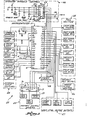
- the microcomputer 21 is operable, under program control, to utilize the inputs from the control section 22 and switch section 24 to produce appropriate output signals for the display section 23 and the various controlled outputs 25, 26 and 27.
- the interaction between the microcomputer 21 and the operator variable controls 22 and displays 23 shall be described in more detail hereinafter.
- the external input switches 24 provide on-off input information to the microcomputer 21 so that the microcomputer can operate the displays and controlled outputs.
- the EMERGENCY STOP, FRAME UP, and CYCLE START switches are operator available pushbutton switches. As indicated above in regard to the general operation of the skin packaging machine 10, the operator depresses the FRAME UP switch to position the frame adjacent the oven, and depresses the CYCLE START switch in order to begin a cycle of skin packaging.
- the IN FEED COMPLETE switch indicates that a loaded card has been positioned on the base 11.
- the CUT OFF FORWARD switch indicates the film-cutting knife position.
- the FRAME CLOSED switch indicates that the next section of film from the roll has been clamped and that the frame may rise.
- the other three FRAME switches are limit switches indicating frame position.
- the microcomputer 21 controls a group of full voltage, 120 volts ac, outputs 25.
- these controls are for energization of magnets holding the film clamp together, a solenoid for closing the film clamp, a solenoid for opening the film clamp, a solenoid for controlling blow off (which is utilized in a blister pack variation of the above described film packaging method) a solenoid controlling the application of additional vacuum, and the relays operable to move the frame up and down.
- the microcomputer In order to control the machine cycle in the response to a given one of the variable controls 22, the microcomputer addresses a multi-channel analog-to-digital converter and reads the control setting. The microcomputer converts the control setting to a usable parameter value and effects the operation of the appropriate outputs. If the particular control is a timing control, the microcomputer internally times out the appropriate length of time for that segment of the machine cycle. If the particular control has a corresponding indicator 23, the microcomputer maintains that indicator energized during the respective cycle segment by the operation of a latch 31.
- Each of the operator variable controls in the control section 22 comprises a potentiometer 32, the output of which is coupled to the analog-to-digital converter 29 and is settable between ground and a reference voltage.
- Each of the potentiometers except for STAND BY HEAT, provide at their wiper arm outputs a voltage indicative of a percentage of a period of time.
- the maximum period of time for the PREHEAT FILM potentiometer is 60 seconds and the output of the potentiometer represents a range between zero and 100% of that time duration.
- the STAND BY HEAT potentiometer setting is indicative of between zero and 50% of the maximum oven energization when the oven is not actually heating the film.
- the analog-to-digital converter 29 is a Motorola type MC14443 analog-to-digital converter linear subsystem.
- the various operations such as addressing, counting, etc. are provided by the microcomputer 21.
- the microcomputer 21 is an Intel 8748-8 single component 8-bit microcomputer.
- the microcomputer 21 also supplies the addressing and control signals for the latch 31, which is a National Semiconductor CD4099 addressable latch.
- the microcomputer first responds to the depression of the FRAME UP button to move the frame adjacent the oven.
- the microcomputer is then responsive to the depression of the CYCLE START button to begin a cycle of operation of the skin packaging machine wherein the microcomputer sequentially executes the various routine segments for the machine cycle.
- the microcomputer also effects the operation of an internal timer which times out repeatedly approximately every 34 milliseconds using a 3.58 megahertz crystal. This enables the microcomputer to issue the appropriate output commands on a real time basis.
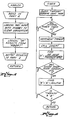
- the PREHEAT FILM segment of the machine cycle routine begins. First, the maximum segment time, 60 seconds, for the PREHEAT FILM segment is loaded into a register MAXTIM. 06D5 is a hexadecimal number representing the count required, for counts occurring every 34 milliseconds, to achieve 60 seconds. Next, the address for channel 5 (the input from potentiometer 32 to the A/D converter 29) is placed into another register designated RBOR7. Then, an indicator latch routine is executed to clear the indicators 23 and then establish the proper indicator on as defined by the contents of the register RBOR7. This routine is illustrated in Figure 4.
- the address latch routine establishes the address defined in the contents of RBOR7 for both the latch 31 and the converter 29,. Since the microcomputer port 2, terminals P20-P27, must be addressed as a group, the ADDLCH routine is necessary to produce changes only on the address lines P23-P21. The sequential AND OR operations in this routine leave the other port 2 lines at their original state. The channel 5 address is thereby also placed on the lines P23-P21.
- the latch 31 (addressed with the channel 5 PREHEAT FILM address) is set to energize the PREHEAT FILM indicator 33.
- the latch will maintain this indicator energized regardless of further changes on the address lines P23-P21 until the latch is cleared, such as at the beginning at the next main routine segment.
- TMRWSP timer work space
- the microcomputer then waits until the internal timer has timed out, which will take between 0 and 34 milliseconds depending upon the timer phase when this routine is entered.
- the timer work space register is incremented by one and a conversion routine, COVERT, is executed.
- COVERT This routine is illustrated in Figure 7.
- the COVERT routine performs the actual analog-to-digital conversion of the pot setting.
- the total conversion time is approximately 2.5 milliseconds, maximum, for a 100% potentiometer input.
- the microcomputer 21 cooperates with the converter 29 to count the time required to discharge a capacitor 34. This time is linearly related to the voltage input on an addressed channel of the converter 29, which voltage is transferred to the capacitor.
- the START CONVERTER step effects transfer of the channel 5 voltage to the capacitor. Then there is a delay stabilizing the capacitor voltage.
- the microcomputer determines three capacitor discharge time counts representative of three different voltages associated with the converter 29. First, the microcomputer determines a count corresponding to the ground of the converter 29, then a count representative of the channel 5 input for PREHEAT FILM, and finally, a count representative of the reference voltage level for the converter.
- the conversion routine of Figure 7 concludes by subtracting the zero offset from each of the other two readings prior to returning to the TIMER ROUTINE of Figure 6.
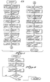
- the COVCNT, conversion count, routine for determining each of the three readings is shown in Figure 8.
- the microcomputer count memory is cleared and then a count accumulated therein until the converter has finished discharging the capacitor 34, which is indicated by the converter CO output going low.
- the counting rate in the count memory is approximately one count every 12.5 microseconds. With the capacitor 34 being .01 microfarads and a resistor 35 associated with the converter being 100 K ohms, the maximum input count is approximately 150.
- the POT INPUT value (with ZERO OFFSET subtracted) is divided by the MAX INPUT value (with ZERO OFFSET subtracted) to develop a ratio A. This ratio is then multiplied by MAXTIM (which in this case is 60 seconds) to determine a segment time B. As long as the accumulated time is TMRSWP (timer work space) is less than B, the microcomputer will operate within the TIMER routine to continue incrementing the timer work space. When the timer work space count becomes greater than or equal to B, the microcomputer returns to the original routine of Figure 3.
- TMRSWP timer work space
- the microcomputer executes the next appropriate commands in accordance with the cycle program. Subsequently, the HEAT PACKAGE segment begins with its associated indicator being latched through the latch 31 and the HEAT PACKAGE segment time being determined in the same manner as that described above for PREHEAT FILM.
- the variable control (and accompanying indicator) to be used is addressed.
- the indicator is turned on (and all others turned off).
- the time delay defined by the variable control is implemented. It should be noted that in implementing the time delay, the TIMER routine ( Figure 6) checks the potentiometer set point every 34 milliseconds. This enables the operator to change the potentiometer setpoint during the time cycle and the controller will effectively "immediately” recognize the change. Otherwise, if only one calculation/ check were made for the potentiometer setpoint, namely, at the beginning of the routine, the operator would not be able to alter the time called for by the potentiometer setting at the beginning.of the delay period. This capability is particularly advantageous when an operator is determining the optimum segment times for a new combination of card, film and objects to be packaged.
- Attached as an Appendix hereto is a program listing for the microcomputer 21 to perform all of the control functions for a skin packaging machine, including the interfacing of the operator variable controls and the utilization of their settings.
Landscapes
- Physics & Mathematics (AREA)
- General Physics & Mathematics (AREA)
- Engineering & Computer Science (AREA)
- Automation & Control Theory (AREA)
- Basic Packing Technique (AREA)
- Vacuum Packaging (AREA)
Applications Claiming Priority (2)
| Application Number | Priority Date | Filing Date | Title |
|---|---|---|---|
| US06/261,749 US4437152A (en) | 1981-05-08 | 1981-05-08 | Control arrangement for multifunction industrial machine |
| US261749 | 2002-09-30 |
Publications (2)
| Publication Number | Publication Date |
|---|---|
| EP0064851A2 true EP0064851A2 (fr) | 1982-11-17 |
| EP0064851A3 EP0064851A3 (fr) | 1984-09-05 |
Family
ID=22994699
Family Applications (1)
| Application Number | Title | Priority Date | Filing Date |
|---|---|---|---|
| EP82302252A Withdrawn EP0064851A3 (fr) | 1981-05-08 | 1982-04-30 | Arrangement de commande pour machine industrielle à fonctions multiples |
Country Status (3)
| Country | Link |
|---|---|
| US (1) | US4437152A (fr) |
| EP (1) | EP0064851A3 (fr) |
| JP (1) | JPS57193806A (fr) |
Cited By (1)
| Publication number | Priority date | Publication date | Assignee | Title |
|---|---|---|---|---|
| EP0413447A3 (en) * | 1989-08-12 | 1992-04-08 | British United Shoe Machinery Limited | Drive arrangement |
Families Citing this family (3)
| Publication number | Priority date | Publication date | Assignee | Title |
|---|---|---|---|---|
| US4641236A (en) * | 1985-05-06 | 1987-02-03 | The Boeing Company | Programmable machine tool control system |
| US4839818A (en) * | 1987-09-25 | 1989-06-13 | Essex Group, Inc. | Magnet wire oven control apparatus |
| US7340543B2 (en) * | 2003-09-24 | 2008-03-04 | Lockheed Martin Corporation | Device and method for discrete signal conditioning |
Family Cites Families (9)
| Publication number | Priority date | Publication date | Assignee | Title |
|---|---|---|---|---|
| US3976981A (en) | 1971-03-02 | 1976-08-24 | Rosemount Engineering Company Limited | Multi-channel control systems |
| US3815313A (en) | 1972-10-04 | 1974-06-11 | R Heisler | Apparatus and method for automatically sizing and wrapping a shrink wrap envelope around advancing luggage |
| US4064394A (en) | 1975-05-28 | 1977-12-20 | American Chain & Cable Company, Inc. | Electronic digital process controller having simulated analog control functions |
| US4188617A (en) | 1976-09-29 | 1980-02-12 | Gulf & Western Industries, Inc. | System for converting analog signals to multiplexed digital data |
| GB1600377A (en) * | 1977-04-16 | 1981-10-14 | British United Shoe Machinery | Shoe upper conforming machines |
| US4180860A (en) | 1977-06-21 | 1979-12-25 | The Foxboro Company | Display station having universal module for interface with different single loop controllers |
| US4172280A (en) | 1977-12-29 | 1979-10-23 | Honeywell Inc. | Digital output control circuit |
| US4189765A (en) | 1978-03-27 | 1980-02-19 | Robertshaw Controls Company | Digital controller |
| US4391079A (en) * | 1980-08-21 | 1983-07-05 | Hayssen Manufacturing Company | Control system for cyclic machines |
-
1981
- 1981-05-08 US US06/261,749 patent/US4437152A/en not_active Expired - Fee Related
-
1982
- 1982-04-30 EP EP82302252A patent/EP0064851A3/fr not_active Withdrawn
- 1982-05-07 JP JP57075541A patent/JPS57193806A/ja active Pending
Cited By (1)
| Publication number | Priority date | Publication date | Assignee | Title |
|---|---|---|---|---|
| EP0413447A3 (en) * | 1989-08-12 | 1992-04-08 | British United Shoe Machinery Limited | Drive arrangement |
Also Published As
| Publication number | Publication date |
|---|---|
| US4437152A (en) | 1984-03-13 |
| EP0064851A3 (fr) | 1984-09-05 |
| JPS57193806A (en) | 1982-11-29 |
Similar Documents
| Publication | Publication Date | Title |
|---|---|---|
| US5792395A (en) | Plasticization control method for an injection molding machine | |
| US4361792A (en) | Digital induction motor control system | |
| EP0313768B1 (fr) | Système de régulation pour un four | |
| US4951444A (en) | Multi-station die-less packaging machine | |
| EP0406435B1 (fr) | Procede et dispositif d'automatisation de travail pour une machine hydraulique a commande electronique | |
| JPH0872115A (ja) | 射出成形機の温度制御方法 | |
| GB2195616A (en) | Apparatus for controlling a pile-lifting device | |
| EP1206346A1 (fr) | Systeme de commande et procede de reglage souples de machine de fabrication de boites | |
| US4437152A (en) | Control arrangement for multifunction industrial machine | |
| EP0203201A1 (fr) | Methode de determination des conditions operationnelles pour machines de moulage par injection | |
| EP0300053B1 (fr) | Methode de controle d'un moteur d'une machine de moulage par injection | |
| GB2054907A (en) | Device for controlling the water level in a tub of a laundry washing machine | |
| EP0458132A3 (en) | Sequential function chart (sfc) controller for controlling a machine in reverse operation | |
| US4413172A (en) | Method of heat control in a skin packaging machine | |
| EP0233292B1 (fr) | Systeme de commande pour machine de moulage par injection entraine par des servomoteurs | |
| US3777525A (en) | Machine for bending concrete-reinforcing bars | |
| US3036253A (en) | Manual and automatic position control systems | |
| DE851325T1 (de) | Verfahren zur Regelung der Heizung eines Ofens mit Hilfe von unscharfer Logik | |
| NL7905062A (nl) | Electrisch aangedreven kneed- en mengmachine. | |
| JPS6211957B2 (fr) | ||
| EP0329221B1 (fr) | Système de commande électronique pour une chambre de levage de pain | |
| JPS6366613B2 (fr) | ||
| EP0362395A4 (en) | Method and apparatus for injection compression molding | |
| SU1691138A1 (ru) | Система автоматического управлени процессом прессовани торфобрикетов | |
| JP3028868B2 (ja) | 射出成形機の運転条件設定方法 |
Legal Events
| Date | Code | Title | Description |
|---|---|---|---|
| PUAI | Public reference made under article 153(3) epc to a published international application that has entered the european phase |
Free format text: ORIGINAL CODE: 0009012 |
|
| AK | Designated contracting states |
Designated state(s): DE FR GB |
|
| 17P | Request for examination filed |
Effective date: 19830503 |
|
| PUAL | Search report despatched |
Free format text: ORIGINAL CODE: 0009013 |
|
| AK | Designated contracting states |
Designated state(s): DE FR GB |
|
| STAA | Information on the status of an ep patent application or granted ep patent |
Free format text: STATUS: THE APPLICATION HAS BEEN WITHDRAWN |
|
| 18W | Application withdrawn |
Withdrawal date: 19851105 |
|
| RIN1 | Information on inventor provided before grant (corrected) |
Inventor name: JONES, STEPHEN H. |