EP0064859A1 - Bandkassette - Google Patents
Bandkassette Download PDFInfo
- Publication number
- EP0064859A1 EP0064859A1 EP82302286A EP82302286A EP0064859A1 EP 0064859 A1 EP0064859 A1 EP 0064859A1 EP 82302286 A EP82302286 A EP 82302286A EP 82302286 A EP82302286 A EP 82302286A EP 0064859 A1 EP0064859 A1 EP 0064859A1
- Authority
- EP
- European Patent Office
- Prior art keywords
- supply reel
- reel
- tape
- rotation
- take
- Prior art date
- Legal status (The legal status is an assumption and is not a legal conclusion. Google has not performed a legal analysis and makes no representation as to the accuracy of the status listed.)
- Granted
Links
Images


Classifications
-
- G—PHYSICS
- G11—INFORMATION STORAGE
- G11B—INFORMATION STORAGE BASED ON RELATIVE MOVEMENT BETWEEN RECORD CARRIER AND TRANSDUCER
- G11B23/00—Record carriers not specific to the method of recording or reproducing; Accessories, e.g. containers, specially adapted for co-operation with the recording or reproducing apparatus ; Intermediate mediums; Apparatus or processes specially adapted for their manufacture
- G11B23/02—Containers; Storing means both adapted to cooperate with the recording or reproducing means
- G11B23/04—Magazines; Cassettes for webs or filaments
Definitions
- This invention relates generally to tape cassettes.
- VTR video tape recorder
- video tape cassettes are capable of being reproduced, rewound and then reproduced again.
- movement of the supply reel in the rewind direction is prevented by biasing a rotatable element into contact with a flange section of the supply reel.
- the flange section of the supply reel includes a number of recesses or teeth around the outer periphery of the reel.
- a tape cassette comprising:
- a previously proposed tape cassette 1 for example, a video tape cassette for a VTR, permits movement of the magnetic tape T therein only in the forward direction and prevents movement of the tape T in the rewind direction.
- a supply reel 3 and take-up reel 4 are rotatably positioned within the lower half 2A of a cassette housing 2 of the tape cassette 1, the cassette housing 2 including a front wall 7 formed in a substantially inverted V-shaped configuration.
- the tape T is wound about the supply reel 3 and the , take-up reel 4 and extends therebetween and, in particular, the tape T extends from the supply reel 3, around a supply side guide roller 5, through a first opening 8S in the front wall 7 adjacent to the guide roller 5, through a second opening 8T in the opposite take-up side of the front wall 7, around a take-up side guide roller 6 and onto the take-up reel 4.
- An L-shaped tape position regulating element 9 is also provided and extends from the centre of the V-shaped configuration of the front wall 7 about the tape T to prevent sagging or looseness of the tape T where it extends between openings 8S and 8T.
- the supply reel 3 and the take-up reel 4 each have respective lower reel flange sections 3A and 4A, respectively, which are formed along their respective peripheries 3a and 4a, respectively, with a plurality of recesses or teeth 11.
- Reel lock members 10 are provided on the supply and take-up sides and are arranged to engage with the teeth 11 of the reels 3 and 4 to prevent rotation when the tape cassette 1 is not in use. In this manner, sagging of the tape T is prevented when the tape cassette 1 is not in use.
- a front cover (not shown) provided on the front wall 7 of the tape cassette 1 is opened, which results in the reel lock members 10 being disengaged from the teeth 11 of the reels 3 and 4.
- the front cover is closed, whereby the reel lock members 10 are engaged with the teeth 11 to prevent rotation of the reels 3 and 4.
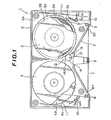
- the tape cassette 1 includes a reel lock mechanism 12 disposed at an intermediate position betwen the supply reel 3 and the take-up reel 4 inside the cassette housing 2.
- the reel lock mechanism 12 includes a support pin 13 projecting perpendicularly from the bottom of the lower half 2A of the cassette housing 2, and an eccentric roller 14 rotatably mounted on the support pin 13.
- a coil spring 15 is also provided for biasing the roller 14 in the clockwise direction about the support pin 13, as viewed in Figure 1, such that the outer periphery 14A of the roller 14 is in contact with both outer peripheries 3a and 3b of the lower and upper flange sections 3A and 3B, respectively, of the supply reel 3.
- the roller 14 When the supply reel 3 is rotated in the direction of the arrow in Figure 1, that is, in the rewind direction, the roller 14 is urged in the clockwise direction and is wedged against the outer peripheries 3a and 3b of the flange sections 3A and 3B, respectively, to prevent rotation of the supply reel 3.
- the roller 14 when the supply reel 3 is rotated in the normal forward direction, that is in a direction opposite to the arrow in Figure 1, the roller 14 is urged in the counter-clockwise direction, while still in contact with the outer peripheries 3a and 3b of the flange sections 3A and 38, respectively. In this manner, the reel lock mechanism 12 prevents movement of the tape T in the rewind direction, while permitting free movement of the tape T in the forward direction.
- a reel lock mechanism 21 is provided in place of the reel lock mechanism 12 of Figure 1 for preventing rotation of the supply reel 3 in the rewind direction, shown by the arrow in Figure 2, while permitting rotation of the supply reel 3 in the normal forward direction.
- the reel lock mechanism 21 is disposed at an intermediate position between the supply reel 3 and the take-up reel 4 in the cassette housing 2 and includes a support pin 22 projecting perpendicularly from the bottom of the lower half 2A of the cassette housing 2, a rotatable control member 23 for preventing movement of the supply reel 3 in the direction of the arrow of Figure 2, while permitting movement thereof in the reverse direction, and a reel lock release device 30 for releasing the control member 23 from the supply reel 3 so as to permit rotation of the supply reel 3 in the rewind direction.
- the control member 23 includes a reel contacting plate 24 having a substantially parallelogram configuration and which, as will be discussed in greater detail hereinafter, is in a resiliently abutting relation with the underside 50 of the lower flange section 3A of the supply reel 3.
- the upper surface 27 of the reel contacting plate 24 is preferably knurled or has a frictional contact member applied thereto to provide increased frictional resistance to relative movement when the surface 27 contacts the underside 50 of the lower flange section 3A of the supply reel 3.
- a ring portion 26 is secured to one side 24a of the reel receiving member 24 and is bent at a predetermined angle thereto.
- the ring portion 26 includes an aperture,25 for rotatably supporting the control member 23 on the support pin 22, as shown in Figure 5. In this manner, because of the predetermined angle of the ring portion 26 with respect to the reel contacting plate 24, the reel contacting plate 24 extends upwardly at an angle when the control member 23 is mounted on the support pin 22.
- the control member 23 also includes a reel lock member 28 which extends perpendicularly from an edge of the reel contacting plate 24 adjacent to the ring portion 26 for preventing movement of the supply reel 3 in the rewind direction. In particular, a forward end 28a .
- the reel lock member 28 is arranged to be disengaged and engaged with the teeth 11 of the lower flange section 3A of the supply reel 3, as shown in Figures 8 and 9, respectively, for permitting movement of the supply reel 3 in the forward direction and preventing movement of the supply reel 3 in the rewind direction.
- the reel lock release device 30, as shown in Figures 6A and 6B, includes a cylindrical portion 32 having a longitudinal bore 31 into which the support pin 22 is arranged to be inserted. In this manner, when the tape cassette 20 is assembled, the cylindrical portion 32 sits over the support pin 22 and on the ring portion 26 to prevent vertical movement of the ring portion 26 on the support pin 22.
- a first tongue or projection 33 extends tangentially from the outer periphery of the cylindrical portion 32 at the lower end 32a thereof for releasing the reel lock member 28 from the teeth 11 of the lower flange section 3A, to permit rotation of the supply reel 3 in the rewind direction.
- a second tongue or projection 34 extends tangentially from the outer periphery of the cylindrical portion 32 at an upper or middle end thereof and at right angles to the first tongue 33.
- the tongue 33 and the cylindrical portion 32 are likewise biased in the same direction.
- the tongues 33 and 34 and the cylindrical portion 32 can be formed as an integral moulded member, for example, of a synthetic resin.
- the control member 23 is positioned over the support pin 22 such that the upper surface 27 thereof is positioned below the underside 50 ( Figure 7) of the lower flange section 3A.
- the reel lock release device 30 is then mounted on the support pin 22, as shown in Figure 5. It is to be appreciated that at this time the reel contacting plate 24 is inclined upwardly with respect to the ring portion 26.
- the supply reel 3 is urged towards the lower half 2A of the cassette housing 2 by a reel biasing leaf spring 35 provided on the underside of the upper half 2B of the cassette housing 2, as shown in Figure 7.
- the reel contacting plate 24 is biased towards the bottom of the lower half 2A of the cassette housing 2 by the leaf spring 35, whereby the surface 27 of the reel contacting plate 24 is maintained in a resiliently biased contact state with the underside 50 of the lower flange section 3A.
- the ring portion 26 of the control member 23 thereby tends to move upwardly along the support pin 22, raising the reel lock release device 30. This latter movement, however, is restricted by the engagement of the upper end 32b of the cylindrical portion 32 of the reel lock lease device 30 with the underside of the upper half 2B of the cassette housing 2.
- a tool insertion aperture 40 is provided, as shown in Figures 8 to 10, for biasing the tongue 34 in the direction of arrow A' of Figure 8 thereby to rotate the reel lock member 28 out of engagement with the teeth 11 of the lower flange section 3A.
- a reel lock release tool 41 as shown in Figures 11A and 11B, of a substantially L-shaped configuration is provided, and includes a piercing portion 42 which is arranged to be inserted into the aperture 40 such that the end 42a thereof engages with the tongue 34 for biasing the tongue 34 in the direction of the arrow A' of Figure 8.
- a recess 43 is provided at the attached end of the piercing portion 42 for locking the tool 41 into the aperture 40.
- the aperture 40 is concealed by the tape T.
- the aperture 40 is located in the front wall 7 of the cassette housing 2, which is enclosed by a front cover (not shown), it becomes difficult for the user to see the aperture 40.
Landscapes
- Packaging Of Annular Or Rod-Shaped Articles, Wearing Apparel, Cassettes, Or The Like (AREA)
- Unwinding Webs (AREA)
- Automatic Tape Cassette Changers (AREA)
Priority Applications (1)
| Application Number | Priority Date | Filing Date | Title |
|---|---|---|---|
| AT82302286T ATE21183T1 (de) | 1981-05-06 | 1982-05-05 | Bandkassette. |
Applications Claiming Priority (2)
| Application Number | Priority Date | Filing Date | Title |
|---|---|---|---|
| JP56066827A JPS57183678A (en) | 1981-05-06 | 1981-05-06 | Tape cassette |
| JP66827/81 | 1981-05-06 |
Publications (2)
| Publication Number | Publication Date |
|---|---|
| EP0064859A1 true EP0064859A1 (de) | 1982-11-17 |
| EP0064859B1 EP0064859B1 (de) | 1986-07-30 |
Family
ID=13327053
Family Applications (1)
| Application Number | Title | Priority Date | Filing Date |
|---|---|---|---|
| EP82302286A Expired EP0064859B1 (de) | 1981-05-06 | 1982-05-05 | Bandkassette |
Country Status (7)
| Country | Link |
|---|---|
| US (1) | US4482104A (de) |
| EP (1) | EP0064859B1 (de) |
| JP (1) | JPS57183678A (de) |
| KR (1) | KR880001551B1 (de) |
| AT (1) | ATE21183T1 (de) |
| CA (1) | CA1170360A (de) |
| DE (1) | DE3272288D1 (de) |
Cited By (10)
| Publication number | Priority date | Publication date | Assignee | Title |
|---|---|---|---|---|
| EP0139181A1 (de) * | 1983-09-27 | 1985-05-02 | D. La Porte Söhne Gmbh | Sicherungseinrichtung für eine Videokassette |
| EP0144802A1 (de) * | 1983-11-09 | 1985-06-19 | Sony Corporation | Magnetbandkassette |
| GB2163726A (en) * | 1984-07-25 | 1986-03-05 | Basf Ag | Spring mounting of a brake element in a tape cassette |
| EP0120611A3 (en) * | 1983-03-02 | 1987-01-14 | Edward J. Dickson | Tape cassette with clutch assembly |
| EP0247252A1 (de) * | 1986-04-01 | 1987-12-02 | ARENA RECREATIONS (TORONTO) LIMITED and WILLIAM LAWRENCE HEISEY, a partnership trading as SINGLE PLAY VIDEO | Rückspulmaschine für Bandkassette |
| EP0339916A1 (de) * | 1988-04-26 | 1989-11-02 | Shapecourt Limited | Kassetten für Videobänder oder andere Bänder oder Filme |
| GB2218403A (en) * | 1988-04-26 | 1989-11-15 | Shapecourt Ltd | Video and or other tape or film cassettes |
| EP0344901A3 (de) * | 1988-06-03 | 1991-02-20 | ARENA RECREATIONS (TORONTO) LIMITED and William Lawrence Heisey, a Partnership trading as SINGLE PLAY VIDEO | Bandkassette mit Rückspulsteuerungsmechanismus |
| EP0466008A3 (en) * | 1990-07-07 | 1992-11-25 | Tdk Corporation | Cassette tape |
| GB2298186A (en) * | 1995-02-21 | 1996-08-28 | Tdk Corp | Lock for cassette reel brake |
Families Citing this family (19)
| Publication number | Priority date | Publication date | Assignee | Title |
|---|---|---|---|---|
| US4635879A (en) * | 1984-09-12 | 1987-01-13 | Hitachi Maxell, Ltd. | Tape cassette |
| JPH0731426Y2 (ja) * | 1985-01-19 | 1995-07-19 | ソニー株式会社 | テープカセット |
| US4763218A (en) * | 1985-03-18 | 1988-08-09 | Westfall Wade H | Video tape cassette with internal tape erasing means |
| US4702434A (en) * | 1986-05-19 | 1987-10-27 | Roger Brauer | Tape cassette arrangement |
| US4801107A (en) * | 1986-10-22 | 1989-01-31 | Sotar, Inc. | Cassette locking system |
| US4802048A (en) * | 1986-10-31 | 1989-01-31 | David H. Rubenstein | Limited play tape cassette system |
| AU1383988A (en) * | 1987-03-30 | 1988-09-29 | Williamson, K.L. | Disposable non-rewinding tape cassette |
| US4891712A (en) * | 1987-12-03 | 1990-01-02 | Nfo Research, Inc. | Method of conducting marketing research by using video tape productions |
| US4847718A (en) * | 1987-12-11 | 1989-07-11 | Nfo Research, Inc. | Cassette with erasing means |
| US5023741A (en) * | 1988-10-28 | 1991-06-11 | Polaroid Corporation | Programmable limited play video tape cassette |
| US5052634A (en) * | 1990-01-29 | 1991-10-01 | Shape Inc. | Static tape cassette reel lock |
| US5109314A (en) * | 1990-06-08 | 1992-04-28 | Wright Joey D | Selectively reversible video cassette |
| US5460335A (en) * | 1991-05-31 | 1995-10-24 | Goldstar Co., Ltd. | Reel braking device for use in a deck mechanism |
| US5351909A (en) * | 1992-07-24 | 1994-10-04 | Moore Clay E | Fast-forwarding locking tape cassette |
| US5354013A (en) * | 1993-06-11 | 1994-10-11 | Ouellette Thomas C | Tape cassette fast forward clutch |
| US6155510A (en) * | 1998-12-16 | 2000-12-05 | Merrill Solomon | Limited-use tape cassette |
| US6433962B2 (en) | 1998-12-16 | 2002-08-13 | Merrill Solomon | Limited initial special use tape cassette with unlimited conventional use thereafter |
| JP2003331557A (ja) * | 2002-05-10 | 2003-11-21 | Fuji Photo Film Co Ltd | 記録テープカセット |
| JP4931132B2 (ja) * | 2007-02-16 | 2012-05-16 | 日東工業株式会社 | 電気電子機器収納用箱のアース端子構造 |
Citations (7)
| Publication number | Priority date | Publication date | Assignee | Title |
|---|---|---|---|---|
| US2515190A (en) * | 1944-07-17 | 1950-07-18 | Armour Res Found | Record protector for magnetic recording and reproducing devices |
| US3438590A (en) * | 1966-12-02 | 1969-04-15 | Sanders Associates Inc | Tape cartridge for use with tape recorders |
| US3459390A (en) * | 1967-04-17 | 1969-08-05 | Sanders Associates Inc | Releasable one-way clutch for a tape reel |
| US3606199A (en) * | 1968-04-19 | 1971-09-20 | Ricoh Kk | Device for terminating unwinding of belt-shaped body from a spool |
| US3995319A (en) * | 1974-12-26 | 1976-11-30 | Action Design Limited | Tape recorder cassette adapted to indicate the number of times the tape is played |
| US4163533A (en) * | 1976-12-10 | 1979-08-07 | Sony Corporation | Tape cassette |
| GB2044733A (en) * | 1979-03-06 | 1980-10-22 | Philips Nv | Tape cassette |
Family Cites Families (6)
| Publication number | Priority date | Publication date | Assignee | Title |
|---|---|---|---|---|
| US3174704A (en) * | 1963-09-12 | 1965-03-23 | Edward H Replogle | Restraint apparatus |
| GB1416744A (en) * | 1971-12-01 | 1975-12-03 | Matsushita Electric Industrial Co Ltd | Tape magazine |
| US3862726A (en) * | 1973-07-16 | 1975-01-28 | American Safety Equip | Safety belt device |
| US3974983A (en) * | 1975-06-09 | 1976-08-17 | Burroughs Corporation | Tape feed and rewind cartridge |
| JPS5282389U (de) * | 1975-12-17 | 1977-06-20 | ||
| JPS581904Y2 (ja) * | 1978-02-17 | 1983-01-13 | ソニー株式会社 | テ−プカセツト |
-
1981
- 1981-05-06 JP JP56066827A patent/JPS57183678A/ja active Pending
-
1982
- 1982-04-29 US US06/373,127 patent/US4482104A/en not_active Expired - Lifetime
- 1982-05-04 KR KR8201955A patent/KR880001551B1/ko not_active Expired
- 1982-05-05 EP EP82302286A patent/EP0064859B1/de not_active Expired
- 1982-05-05 DE DE8282302286T patent/DE3272288D1/de not_active Expired
- 1982-05-05 AT AT82302286T patent/ATE21183T1/de active
- 1982-05-05 CA CA000402315A patent/CA1170360A/en not_active Expired
Patent Citations (7)
| Publication number | Priority date | Publication date | Assignee | Title |
|---|---|---|---|---|
| US2515190A (en) * | 1944-07-17 | 1950-07-18 | Armour Res Found | Record protector for magnetic recording and reproducing devices |
| US3438590A (en) * | 1966-12-02 | 1969-04-15 | Sanders Associates Inc | Tape cartridge for use with tape recorders |
| US3459390A (en) * | 1967-04-17 | 1969-08-05 | Sanders Associates Inc | Releasable one-way clutch for a tape reel |
| US3606199A (en) * | 1968-04-19 | 1971-09-20 | Ricoh Kk | Device for terminating unwinding of belt-shaped body from a spool |
| US3995319A (en) * | 1974-12-26 | 1976-11-30 | Action Design Limited | Tape recorder cassette adapted to indicate the number of times the tape is played |
| US4163533A (en) * | 1976-12-10 | 1979-08-07 | Sony Corporation | Tape cassette |
| GB2044733A (en) * | 1979-03-06 | 1980-10-22 | Philips Nv | Tape cassette |
Cited By (14)
| Publication number | Priority date | Publication date | Assignee | Title |
|---|---|---|---|---|
| EP0120611A3 (en) * | 1983-03-02 | 1987-01-14 | Edward J. Dickson | Tape cassette with clutch assembly |
| EP0139181A1 (de) * | 1983-09-27 | 1985-05-02 | D. La Porte Söhne Gmbh | Sicherungseinrichtung für eine Videokassette |
| EP0144802A1 (de) * | 1983-11-09 | 1985-06-19 | Sony Corporation | Magnetbandkassette |
| US4646190A (en) * | 1983-11-09 | 1987-02-24 | Sony Corporation | Magnetic tape cassette having automatic brake |
| GB2163726A (en) * | 1984-07-25 | 1986-03-05 | Basf Ag | Spring mounting of a brake element in a tape cassette |
| EP0247252A1 (de) * | 1986-04-01 | 1987-12-02 | ARENA RECREATIONS (TORONTO) LIMITED and WILLIAM LAWRENCE HEISEY, a partnership trading as SINGLE PLAY VIDEO | Rückspulmaschine für Bandkassette |
| EP0339916A1 (de) * | 1988-04-26 | 1989-11-02 | Shapecourt Limited | Kassetten für Videobänder oder andere Bänder oder Filme |
| WO1989010616A1 (en) * | 1988-04-26 | 1989-11-02 | Shapecourt Limited | Video and other tape or film cassettes |
| GB2218403A (en) * | 1988-04-26 | 1989-11-15 | Shapecourt Ltd | Video and or other tape or film cassettes |
| EP0344901A3 (de) * | 1988-06-03 | 1991-02-20 | ARENA RECREATIONS (TORONTO) LIMITED and William Lawrence Heisey, a Partnership trading as SINGLE PLAY VIDEO | Bandkassette mit Rückspulsteuerungsmechanismus |
| EP0466008A3 (en) * | 1990-07-07 | 1992-11-25 | Tdk Corporation | Cassette tape |
| US5295636A (en) * | 1990-07-07 | 1994-03-22 | Tdk Corporation | Cassette tape with subjectively determined stop position |
| GB2298186A (en) * | 1995-02-21 | 1996-08-28 | Tdk Corp | Lock for cassette reel brake |
| GB2298186B (en) * | 1995-02-21 | 1998-08-05 | Tdk Corp | Tape cassette and recording and reproducing apparatus |
Also Published As
| Publication number | Publication date |
|---|---|
| EP0064859B1 (de) | 1986-07-30 |
| KR880001551B1 (ko) | 1988-08-20 |
| KR840000031A (ko) | 1984-01-30 |
| ATE21183T1 (de) | 1986-08-15 |
| CA1170360A (en) | 1984-07-03 |
| JPS57183678A (en) | 1982-11-12 |
| DE3272288D1 (en) | 1986-09-04 |
| US4482104A (en) | 1984-11-13 |
Similar Documents
| Publication | Publication Date | Title |
|---|---|---|
| EP0064859B1 (de) | Bandkassette | |
| US4232840A (en) | Tape cassette | |
| EP0406943B1 (de) | System zur Aufzeichnung/Wiedergabe von Signalen auf/vom Magnetband und Gerät und Kassette zur Verwendung in diesem System | |
| US4947276A (en) | Magnetic tape cassette with remaining tape indicator | |
| JPS6128300Y2 (de) | ||
| US3781487A (en) | Reel-over-reel video tape cartridge and transport apparatus with sliding pivot | |
| US5121276A (en) | Insertable tape cartridge for videocassette having a reel restraining member | |
| JPH0210502B2 (de) | ||
| US5237479A (en) | Tape cassette with slidable cover | |
| JP2692334B2 (ja) | テープカセット | |
| JPH0329784Y2 (de) | ||
| JP2998546B2 (ja) | テープカセット | |
| JPH0233346Y2 (de) | ||
| JP2900694B2 (ja) | テープカセット | |
| JPS6325555Y2 (de) | ||
| JP3492477B2 (ja) | テープカセット | |
| JP2629431B2 (ja) | テープカセット | |
| JP2616548B2 (ja) | テープカセット | |
| JP3243839B2 (ja) | スプリング部材及びテープカセット | |
| KR200174467Y1 (ko) | 텔레 비디오 카세트 레코더의 도어 안착장치 | |
| JP2900693B2 (ja) | テープカセット | |
| JPS6128301Y2 (de) | ||
| JPS6128284Y2 (de) | ||
| JPH06295556A (ja) | テープカセット | |
| JP2586674B2 (ja) | テープカセット |
Legal Events
| Date | Code | Title | Description |
|---|---|---|---|
| PUAI | Public reference made under article 153(3) epc to a published international application that has entered the european phase |
Free format text: ORIGINAL CODE: 0009012 |
|
| AK | Designated contracting states |
Designated state(s): AT DE FR GB NL |
|
| 17P | Request for examination filed |
Effective date: 19830406 |
|
| GRAA | (expected) grant |
Free format text: ORIGINAL CODE: 0009210 |
|
| AK | Designated contracting states |
Kind code of ref document: B1 Designated state(s): AT DE FR GB NL |
|
| REF | Corresponds to: |
Ref document number: 21183 Country of ref document: AT Date of ref document: 19860815 Kind code of ref document: T |
|
| ET | Fr: translation filed | ||
| REF | Corresponds to: |
Ref document number: 3272288 Country of ref document: DE Date of ref document: 19860904 |
|
| PLBE | No opposition filed within time limit |
Free format text: ORIGINAL CODE: 0009261 |
|
| STAA | Information on the status of an ep patent application or granted ep patent |
Free format text: STATUS: NO OPPOSITION FILED WITHIN TIME LIMIT |
|
| 26N | No opposition filed | ||
| PGFP | Annual fee paid to national office [announced via postgrant information from national office to epo] |
Ref country code: FR Payment date: 19930526 Year of fee payment: 12 |
|
| PGFP | Annual fee paid to national office [announced via postgrant information from national office to epo] |
Ref country code: DE Payment date: 19930729 Year of fee payment: 12 |
|
| PGFP | Annual fee paid to national office [announced via postgrant information from national office to epo] |
Ref country code: GB Payment date: 19940504 Year of fee payment: 13 |
|
| PG25 | Lapsed in a contracting state [announced via postgrant information from national office to epo] |
Ref country code: FR Effective date: 19950131 |
|
| PG25 | Lapsed in a contracting state [announced via postgrant information from national office to epo] |
Ref country code: DE Effective date: 19950201 |
|
| REG | Reference to a national code |
Ref country code: FR Ref legal event code: ST |
|
| PG25 | Lapsed in a contracting state [announced via postgrant information from national office to epo] |
Ref country code: GB Effective date: 19950505 |
|
| GBPC | Gb: european patent ceased through non-payment of renewal fee |
Effective date: 19950505 |
|
| PGFP | Annual fee paid to national office [announced via postgrant information from national office to epo] |
Ref country code: NL Payment date: 19960531 Year of fee payment: 15 |
|
| PGFP | Annual fee paid to national office [announced via postgrant information from national office to epo] |
Ref country code: AT Payment date: 19970521 Year of fee payment: 16 |
|
| PG25 | Lapsed in a contracting state [announced via postgrant information from national office to epo] |
Ref country code: NL Effective date: 19971201 |
|
| NLV4 | Nl: lapsed or anulled due to non-payment of the annual fee |
Effective date: 19971201 |
|
| PG25 | Lapsed in a contracting state [announced via postgrant information from national office to epo] |
Ref country code: AT Free format text: LAPSE BECAUSE OF NON-PAYMENT OF DUE FEES Effective date: 19980505 |