EP0064868A2 - Trennwand - Google Patents
Trennwand Download PDFInfo
- Publication number
- EP0064868A2 EP0064868A2 EP82302329A EP82302329A EP0064868A2 EP 0064868 A2 EP0064868 A2 EP 0064868A2 EP 82302329 A EP82302329 A EP 82302329A EP 82302329 A EP82302329 A EP 82302329A EP 0064868 A2 EP0064868 A2 EP 0064868A2
- Authority
- EP
- European Patent Office
- Prior art keywords
- stud
- studs
- panel
- partition
- panels
- Prior art date
- Legal status (The legal status is an assumption and is not a legal conclusion. Google has not performed a legal analysis and makes no representation as to the accuracy of the status listed.)
- Withdrawn
Links
Images


Classifications
-
- E—FIXED CONSTRUCTIONS
- E04—BUILDING
- E04B—GENERAL BUILDING CONSTRUCTIONS; WALLS, e.g. PARTITIONS; ROOFS; FLOORS; CEILINGS; INSULATION OR OTHER PROTECTION OF BUILDINGS
- E04B2/00—Walls, e.g. partitions, for buildings; Wall construction with regard to insulation; Connections specially adapted to walls
- E04B2/74—Removable non-load-bearing partitions; Partitions with a free upper edge
- E04B2/7407—Removable non-load-bearing partitions; Partitions with a free upper edge assembled using frames with infill panels or coverings only; made-up of panels and a support structure incorporating posts
- E04B2/7409—Removable non-load-bearing partitions; Partitions with a free upper edge assembled using frames with infill panels or coverings only; made-up of panels and a support structure incorporating posts special measures for sound or thermal insulation, including fire protection
- E04B2/7411—Details for fire protection
-
- E—FIXED CONSTRUCTIONS
- E04—BUILDING
- E04B—GENERAL BUILDING CONSTRUCTIONS; WALLS, e.g. PARTITIONS; ROOFS; FLOORS; CEILINGS; INSULATION OR OTHER PROTECTION OF BUILDINGS
- E04B2/00—Walls, e.g. partitions, for buildings; Wall construction with regard to insulation; Connections specially adapted to walls
- E04B2/74—Removable non-load-bearing partitions; Partitions with a free upper edge
- E04B2/7407—Removable non-load-bearing partitions; Partitions with a free upper edge assembled using frames with infill panels or coverings only; made-up of panels and a support structure incorporating posts
- E04B2/7409—Removable non-load-bearing partitions; Partitions with a free upper edge assembled using frames with infill panels or coverings only; made-up of panels and a support structure incorporating posts special measures for sound or thermal insulation, including fire protection
- E04B2/7412—Posts or frame members specially adapted for reduced sound or heat transmission
-
- E—FIXED CONSTRUCTIONS
- E04—BUILDING
- E04B—GENERAL BUILDING CONSTRUCTIONS; WALLS, e.g. PARTITIONS; ROOFS; FLOORS; CEILINGS; INSULATION OR OTHER PROTECTION OF BUILDINGS
- E04B2/00—Walls, e.g. partitions, for buildings; Wall construction with regard to insulation; Connections specially adapted to walls
- E04B2/74—Removable non-load-bearing partitions; Partitions with a free upper edge
- E04B2/76—Removable non-load-bearing partitions; Partitions with a free upper edge with framework or posts of metal
- E04B2/78—Removable non-load-bearing partitions; Partitions with a free upper edge with framework or posts of metal characterised by special cross-section of the frame members as far as important for securing wall panels to a framework with or without the help of cover-strips
- E04B2/7809—Removable non-load-bearing partitions; Partitions with a free upper edge with framework or posts of metal characterised by special cross-section of the frame members as far as important for securing wall panels to a framework with or without the help of cover-strips of single or multiple tubular form
- E04B2/7818—Removable non-load-bearing partitions; Partitions with a free upper edge with framework or posts of metal characterised by special cross-section of the frame members as far as important for securing wall panels to a framework with or without the help of cover-strips of single or multiple tubular form of substantially rectangular form
Definitions
- This invention relates to a partition structure, by which we mean herein a structure which divides from each other adjacent rooms at the same level or at approximately the same level within a building, vehicle, vessel or the like.
- the term "room” embraces spaces in which persons are accommodated for work, leisure, sleeping, eating and washing, and embraces corridors, stairways and landings.
- a partition structure is usually non-load bearing, in the sense that reliance is not placed on the partition structure to support higher parts of the building, vehicle, vessel or the like, but various articles may be mounted on the partition structure so that it bears the load imposed by these articles.
- partition structure is called a stud and panel partition.
- This kind of partition structure generally comprises two skins between which there is a cavity.
- the skins comprise panels, for example of plasterboard, permanently secured to a series of posts called studs.
- Electric cables and water pipes can be concealed in the cavity of a stud and panel partition but they are then substantially inaccessible, except where they emerge from the partition.
- a stud and panel partition structure comprising first and second panels in mutually spaced face-to-face relation, first and second studs which are secured to each other and first and second retaining members secured respectively to the first and second studs, wherein a marginal portion of the first panel is trapped between the first retaining member and the first stud and a marginal portion of the second panel is trapped between the second retaining member and the second stud.
- the retaining members are not required to possess strength and stiffness as great as are possessed by the studs and a retaining member having the same length as the stud may be less massive than the stud.
- first and second studs there is no substantial thermally conductive path between the first and second studs.
- a spacer element formed of a material having a lower thermal conductivity than does the material of which the studs are formed.
- the studs may be held in engagement with respective faces of the spacer element by securing means.
- the securing means is preferably formed separately from the studs but it would be within the scope of the invention for some at least of the securing means to be formed integrally with two studs.
- the retaining members are preferably secured to corresponding studs by releasable fasteners so that a partition structure in accordance with the invention can be partly disassembled in order for access to be gained to service lines behind a panel.
- a stud and panel partition comprising a panel, a pair of studs disposed one adjacent each of two opposite edges of the panel and a pair of retaining members secured one on each stud, wherein each stud is formed with a seat for a marginal portion of the corresponding panel, said marginal portion is trapped between the seat and the corresponding retaining member and each stud includes a flange spaced from the panel in a direction away from the retaining member and at least a part of which flange is spaced from the seat in a direction along the partition.
- the flanges facilitate securing of the studs to corresponding studs of an adjacent partition or to some other underlying structure.
- a stud for a structure according to the first aspect comprising two spaced, substantially flat and co-planar seats for marginal portions of respective panels, a nose which extends from the seats to lie between said panels when the panels are engaged with the seats and two flanges at opposite margins of the stud, each flange being spaced from the plane of the seats in a direction opposite to that in which the nose extends from said plane, being at least approximately parallel to the plane of the seats and having a free edge at its margin furthest from the other flange.
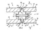
- the structure illustrated in Figure 1 comprises first and second partitions 10 and 11 arranged back-to-back.
- the partitions have the same structure and identical components may be used to construct the two partitions.
- the partition 10 comprises a stud 12 which may be formed by cold rolling from steel strip.
- the stud includes a pair of substantially co-planar flanges 13 and 14 which face towards the partition 11 and have respective free edges 15 and 16 which face away from each other along the partition structure.
- the stud further includes a nose 17 which is remote from the flanges 13 and 14 and faces in a direction away from the partition 11.
- the partition 10 further comprises a pair of panels 18 and 19 having respective edges 20 and 21 which face ' towards each other and between which the nose 17 lies. Respective front faces 22 and 23 of the panels are substantially co-planar and are almost entirely exposed at a face of the partition structure.
- a rear face 24 of the panel 18 is seated on a shoulder 25 presented by the stud 12 at a position between the nose 17 and the flange 13.
- a rear face 26 of the panel 19 is seated on a corresponding shoulder 27 of the stud which lies between the flange 14 and the nose 17.
- the shoulders 25 and 27 are substantially parallel to the flanges 13 and 14. It will be noted that the panels are spaced somewhat from these flanges in a direction towards the exposed face of the partition.
- the partition 10 further comprises a retaining member 28 which is secured by releasable fasteners 29 to the tip of the nose 17.
- the retaining member is of elongated form and extends along almost the entire length of the stud 12.
- the retaining member has the form of a shallow channel and has laterally outwardly projecting flanges 30 and 31 which overlap respective marginal portions of the front faces 22 and 23 of the panels. Marginal portions of the panels are thus trapped between respective flanges of the retaining member and corresponding shoulders on the stud.
- Each panel may be subjected to some degree of compression between the retaining member and stud.
- the retaining member is spaced somewhat from the nose 17 when the panels are compressed between the retaining member and the stud 12.
- the fasteners 29, which are usually of steel, provide the sole thermally conductive path between the retaining member and the stud. This path has a very small cross-sectional area.
- the nose 17 may be substantially shorter than the nose shown in the drawing and the channel of the retaining member correspondingly deeper to receive a snap-in cover strip which may be formed of a plastics material or of metal.
- the channel defined by the retaining member may have a dove-tail form to ensure adequate retention of the cover strip.
- the partition 11 comprises components corresponding to those of the partition 10 and these corresponding components of the partition 11 are indicated by like reference numerals with the prefix 1.
- the panels 18 and 118 are in mutually-spaced face-to-face relation and between them there is a cavity 32 in which service lines can be disposed.
- the cavity could contain a body of thermally and accoustically insulating material and may be filled by such material.
- the partition structure of Figure 1 further comprises a spacer element 33 disposed between the studs 12 and 112.
- the spacer element is in the form of a flat strip having a length almost as great as the length of the studs and being formed of a material which has a lower thermal conductivity than does the metal of which the studs are formed. Material used for lining ceilings to provide resistance to fire or material used to provide resistance to fire in doors may be used to form the spacer element.
- the flanges 13 and 14 are held in contact with one face of the spacer element 33 whilst the flanges 113 and 114 are held in contact with the opposite face of the spacer element by a number of releasable fasteners 34 engaged with the flanges at intervals along the length of the studs.
- the particular fastener provided in the structure of Figure 1 has the form of a metal clip which embraces a pair of adjacent flanges, one from each stud, and overlies respective parts of the free edges of the flanges.
- Each clip is provided with teeth which bear on the flanges so that the area of contact between each clip and the flanges is small.
- each clip provides only a very restricted thermally conductive path between the studs 12 and 112.
- the clips are spaced apart longitudinally of the studs by a distance considerably greater than the spacing of exposed faces-22 and 122 of the panels.
- the clips may be spaced 30cm or more apart. Screws may be used in place of the clips to secure the flanges in contact with the spacer element.
- leach flange has a surface which faces towards the corresponding panel but is spaced therefrom and is exposed by other parts of the stud so that, prior to application of the associated panel, a fastener can be engaged easily with the exposed surface of the flange without the fastener subsequently obstructing proper seating of the associated panel on its shoulder.
- the primary function of the clips 34 is to maintain the thermally insulating spacer element 33 between the studs 12 and 112.
- the studs have sufficient stiffness to resist significant bending under normal conditions of use. If a stud is subjected to an unusually large bending load, a part of that load can be transmitted through the spacer element 33 to the other stud without excessive deflection of either of the studs, provided the studs are held in firm contact with the spacer element.
- a secondary function of the clips is to maintain firm contact between the flanges of the studs and the spacer element and thus to make a contribution to the stiffness of the structure.
- each of the panels 18, 19, 118 and 119 is preferably a laminate comprising at least a relatively thin front layer 35 which is capable of withstanding wear and a rear layer 36 which has a relatively low thermal conductivity.
- the front layer may be sheet metal or a plastics material.
- the rear layer is preferably formed of mineral wool.
- the retaining member 28 is preferably formed of sheet steel.
- a selected panel can be demounted from the partition structure if the retaining members engaged with that panel are first removed. Thus, access can be gained to service lines within the cavity 32.
- a reinforcing board or plate may be provided in the cavity 32 and adhered to the panel 18. Fittings or appliances can then be mounted on the panel 18 by means of fasteners engaged with the reinforcing board or plate. Since the reinforcing board or plate can be applied to the panel after the partition structure has been completed, the position in which the appliance or fitting is to be mounted can be chosen when the appliance or fitting is to be mounted on the partition structure.
- each of the studs 12 and 112 projects from the panels with which it is engaged in a direction towards the panels associated with the other stud for a distance not exceeding twice the thickness of the panels.
- the overall thickness of the partition structure is not excessive, notwithstanding the presence of the spacer 33 between the studs.
- the studs may be modified to position the flange 13 and other corresponding flanges nearer to the shoulder 25 and the respective other shoulders. These flanges and those parts of the studs intervening between the flanges and the shoulders may be omitted entirely.
- fasteners for securing the studs together would be engaged with the shoulders on which the panels are seated.
- the shoulders or the panels or both may be recessed to accommodate the fasteners without spacing the panels from the shoulders.
- the flange 13 is spaced from the panel 18 by a distance not exceeding the thickness of the panel.
- the partition structure is connected with a ceiling 37 by means of an inverted channel 38 which is secured to the ceiling prior to erection of the partition structure.
- the channel is provided with two depending limbs 51 and 52 which lie between and are parallel to the sides of the channel. These limbs may be provided on angle section elements secured to the base of the channel and are spaced somewhat apart.
- the panels associated with the stud 12 are inserted into the channel by raising the upper edges of the panels to lie between the shoulder 25 and the adjacent side of the channel which holds the panels in engagement with the stud.
- an upper end portion of that member also may be introduced into the channel.
- the partition 11 is assembled with the channel in a similar way so that the partition structure is then trapped within the channel, flanges 30, 31, 130 and 131 of the retaining members engaging side walls 39 and 40 of the channel. These side walls may have horizontal flanges to support respective suspended ceilings.
- the studs 12 and 112 are secured to a floor 41 by a pair of angle section brackets 42 and 43 respectively.
- One limb of each bracket is screwed to the floor 41 and further limbs of the brackets project vertically upwards in mutually spaced parallel relation to be received between the flanges 13 and 113 and between the flanges 14 and 114.
- These flanges are secured to the brackets by screws or other fasteners.
- the upright flanges of the brackets 42 and 43 are received in the gap between the studs 12 and 112 and are spaced apart so that the brackets do not provide a thermally conductive path between opposite faces of the partition structure. If required, similar brackets may be used to connect the studs with the ceiling.
- the studs 12 and 112 would be connected to the ceiling 37 by the channel 38 and connected to the floor 41 by the brackets 42 and 43 prior to assembly of the panels with the studs.
- Service lines for example electric cables and water pipes may then be installed in the partition structure in such positions that, when the panels of the partition structure are added, the service lines will lie in the cavities between panels.
- the partition structure illustrated in Figure 3 comprises partitions 45 and 46 arranged in mutually spaced back-to-back relation and a further pair of partitions 47 and 48 arranged in mutually spaced back-to-back relation and extending from the partition 46 in a direction away from the partition 45 and generally at right angles to the partitions 45 and 46.
- the partition 45 may be identical with the partition 10 hereinbefore described.
- the partitions 46, 47 and 48 are each generally similar to the partition 10 but differ therefrom in that, at the junction of the partition 46 with the other two partitions, there is provided a first stud 49 common to the partitions 46 and 47 and a second stud 50 common to the partitions 46 and 48.
- the studs 49 and 50 have the same form which differs from that of the stud 12.
- the stud 49 has at opposite lateral margins respective flanges 51 and 52 which present respective free edges of the stud. These flanges are mutually perpendicular and between the flanges the stud presents a series of mutually perpendicular shoulders, there being at least one shoulder parallel to the flange 51 and at least one shoulder parallel to the flange 52.
- Respective panels 53 and 54 of the partitions 46 and 47 are held in engagement with these two shoulders by a retaining element (not shown) releasably secured to the stud 49. Further panels 55 and 56 of the partitons 46 and 48 respectively are held in engagement with corresponding shoulders of the stud 50.
- the flange 51 of the stud,49 and the corresponding flange of the stud 50 are held in engagement with the same face of a somewhat wider spacer element 59, an opposite face of which is engaged by a stud of the partition 45. Clips or other releasable fasteners may be used to maintain these flanges in engagement with the spacer element 59.
- FIG 4 there is illustrated a structure comprising four partitions 60 to 63.
- the partitions 60 and 61 are arranged in mutually spaced back-to-back relation whilst the partitions 62 and 63 are arranged in mutually spaced back-to-back relation but extend at right angles to the partitions 61 and 62.
- Each of the partitions 60 to 63 may be formed of the components hereinbefore described in relation to the partition 10.
- Parts of the partitions 60 to 63 which correspond to parts of the partition 10 are indicated in Figure 4 by like reference numerals with the prefixes 2,3,4 and 5 respectively and the description of the components of the partition 10 is deemed to apply to these corresponding components.
- An external corner piece 64 which may be formed of the same materials as the panels and which, as viewed in plan, comprises two limbs which meet at a right angle, is engaged with the studs 212 and 512 and held against shoulders thereon by the retaining members 228 and 528 respectively.
- the partition 10 may be used to line a wall constructed of different materials.
- the studs of the partition may be spaced from the wall by spacer elements 33.
- the studs may abut and be secured directly to the wall. With either of these arrangements, there would be defined between the panels 18 and 19 on the one hand and the wall on the other hand a cavity.
Landscapes
- Engineering & Computer Science (AREA)
- Architecture (AREA)
- Physics & Mathematics (AREA)
- Electromagnetism (AREA)
- Civil Engineering (AREA)
- Structural Engineering (AREA)
- Thermal Sciences (AREA)
- Building Environments (AREA)
- Apparatus Associated With Microorganisms And Enzymes (AREA)
- Medical Preparation Storing Or Oral Administration Devices (AREA)
- Infusion, Injection, And Reservoir Apparatuses (AREA)
- Rod-Shaped Construction Members (AREA)
- Installation Of Indoor Wiring (AREA)
Applications Claiming Priority (2)
| Application Number | Priority Date | Filing Date | Title |
|---|---|---|---|
| GB8114258 | 1981-05-09 | ||
| GB8114258 | 1981-05-09 |
Publications (2)
| Publication Number | Publication Date |
|---|---|
| EP0064868A2 true EP0064868A2 (de) | 1982-11-17 |
| EP0064868A3 EP0064868A3 (de) | 1982-12-15 |
Family
ID=10521699
Family Applications (1)
| Application Number | Title | Priority Date | Filing Date |
|---|---|---|---|
| EP82302329A Withdrawn EP0064868A3 (de) | 1981-05-09 | 1982-05-07 | Trennwand |
Country Status (3)
| Country | Link |
|---|---|
| EP (1) | EP0064868A3 (de) |
| GB (1) | GB2103260B (de) |
| NO (1) | NO821508L (de) |
Cited By (2)
| Publication number | Priority date | Publication date | Assignee | Title |
|---|---|---|---|---|
| NL1014347C2 (nl) * | 2000-01-28 | 2001-08-13 | Arthur Chou | Constructie voor een scheidingswand. |
| US20240189636A1 (en) * | 2009-09-21 | 2024-06-13 | Cemco, Llc | Wall gap fire block device, system and method |
Families Citing this family (6)
| Publication number | Priority date | Publication date | Assignee | Title |
|---|---|---|---|---|
| GB8319509D0 (en) * | 1983-07-19 | 1983-08-17 | Quedron Frameless Buildings Lt | Partition |
| GB8629060D0 (en) * | 1986-12-04 | 1987-01-14 | Stramit Ind Uk Ltd | Double skin roof/wall structure |
| US4918879A (en) * | 1987-05-29 | 1990-04-24 | Commercial And Architectural Products, Inc. | Merchandising wall structure including readily attachable and detachable panels and having plastic reveals |
| GB2318148B (en) * | 1996-10-10 | 2000-10-11 | Komfort Systems Ltd | Partitioning system |
| GB2339589B (en) * | 1998-07-14 | 2000-04-26 | Faram Limited | Glazing dry joints |
| DE29915102U1 (de) * | 1999-08-28 | 2001-01-18 | Roehse, Thomas, 38350 Helmstedt | Systemtrennwand |
Family Cites Families (5)
| Publication number | Priority date | Publication date | Assignee | Title |
|---|---|---|---|---|
| DE1879211U (de) * | 1963-04-09 | 1963-09-12 | Knauf Westdeutsche Gips | Bauelementensatz fuer eine montagewand. |
| DE1911701U (de) * | 1963-06-11 | 1965-03-11 | Theodor Keller | Schall- und waerme-isolier-traeger. |
| NO116517B (de) * | 1966-07-08 | 1969-04-08 | Hetas A S Treteknikksentret | |
| US4028856A (en) * | 1976-01-26 | 1977-06-14 | Mallyclad Corporation | Cover wall construction |
| DE2800252A1 (de) * | 1978-01-04 | 1979-07-05 | Vki Rheinhold & Mahla Ag | Verfahren zur herstellung einer waermegedaemmten, aus mehreren schichten bestehenden wand |
-
1982
- 1982-05-07 EP EP82302329A patent/EP0064868A3/de not_active Withdrawn
- 1982-05-07 NO NO821508A patent/NO821508L/no unknown
- 1982-05-07 GB GB08213268A patent/GB2103260B/en not_active Expired
Cited By (2)
| Publication number | Priority date | Publication date | Assignee | Title |
|---|---|---|---|---|
| NL1014347C2 (nl) * | 2000-01-28 | 2001-08-13 | Arthur Chou | Constructie voor een scheidingswand. |
| US20240189636A1 (en) * | 2009-09-21 | 2024-06-13 | Cemco, Llc | Wall gap fire block device, system and method |
Also Published As
| Publication number | Publication date |
|---|---|
| GB2103260A (en) | 1983-02-16 |
| EP0064868A3 (de) | 1982-12-15 |
| GB2103260B (en) | 1985-09-18 |
| NO821508L (no) | 1982-11-10 |
Similar Documents
| Publication | Publication Date | Title |
|---|---|---|
| US4712352A (en) | Modular construction system | |
| US3788021A (en) | Interconnection system for structural elements | |
| US4936069A (en) | Modular building panel having an improved offset thermal barrier joint | |
| US4038799A (en) | Joiner bulkhead method and apparatus | |
| US3309826A (en) | Resiliently mounted dry wall partition for building structures | |
| US5125201A (en) | Joints and connector mechanisms for wall systems | |
| US2362252A (en) | Wall structure | |
| US11091908B2 (en) | Thermal and acoustic insulating and sealing means for a safing slot in a curtain wall | |
| US20090126297A1 (en) | Thermal insulation and sealing means for a safing slot | |
| EP0102825A2 (de) | System für eine demontierbare Trennwand | |
| CA2851058C (en) | Modular system for sub-ceilings | |
| EP0247811A2 (de) | Wand- bzw. Verkleidungsaufbau | |
| CA2874327C (en) | Conventional fire-rated one-sided construction | |
| US1999741A (en) | Partition wall construction | |
| EP0270541A1 (de) | Ein pfostenaufbau welcher sich vom boden zur decke ausdehnt mit aufhängbaren paneelen zum aufbauen demontierbarer zwischenwände. | |
| GB2103260A (en) | Partition structure | |
| US5749197A (en) | Panel joint system | |
| US3927500A (en) | Fire resistant paneling system | |
| EP0570374A1 (de) | Rahmen für teilungswände | |
| CN214006250U (zh) | 一种装配式建筑隔音隔热预制墙板 | |
| GB1331269A (en) | Sound insulation of buildings | |
| US3867802A (en) | Floor support assembly for building structures | |
| US3535842A (en) | Fire-resistant removable wall panel | |
| US3943680A (en) | Stud having kerf-engaging flange and fire-retardant wall structure formed therewith | |
| US3255564A (en) | Structural partitioning system |
Legal Events
| Date | Code | Title | Description |
|---|---|---|---|
| PUAI | Public reference made under article 153(3) epc to a published international application that has entered the european phase |
Free format text: ORIGINAL CODE: 0009012 |
|
| PUAL | Search report despatched |
Free format text: ORIGINAL CODE: 0009013 |
|
| AK | Designated contracting states |
Designated state(s): AT BE CH DE FR GB IT LU NL SE |
|
| AK | Designated contracting states |
Designated state(s): AT BE CH DE FR GB IT LI LU NL SE |
|
| STAA | Information on the status of an ep patent application or granted ep patent |
Free format text: STATUS: THE APPLICATION IS DEEMED TO BE WITHDRAWN |
|
| 18D | Application deemed to be withdrawn |
Effective date: 19831123 |
|
| RIN1 | Information on inventor provided before grant (corrected) |
Inventor name: ECCLESHALL, DAVID JOHN |