EP0064899A2 - Einrichtung zur Übertragung von Bildern mittels eines optischen Kabels und Verwendung bei einer Videokamera - Google Patents
Einrichtung zur Übertragung von Bildern mittels eines optischen Kabels und Verwendung bei einer Videokamera Download PDFInfo
- Publication number
- EP0064899A2 EP0064899A2 EP82400695A EP82400695A EP0064899A2 EP 0064899 A2 EP0064899 A2 EP 0064899A2 EP 82400695 A EP82400695 A EP 82400695A EP 82400695 A EP82400695 A EP 82400695A EP 0064899 A2 EP0064899 A2 EP 0064899A2
- Authority
- EP
- European Patent Office
- Prior art keywords
- image
- face
- prism
- objective
- optical
- Prior art date
- Legal status (The legal status is an assumption and is not a legal conclusion. Google has not performed a legal analysis and makes no representation as to the accuracy of the status listed.)
- Withdrawn
Links
- 230000003287 optical effect Effects 0.000 title claims abstract description 22
- 239000000835 fiber Substances 0.000 claims description 17
- 239000006185 dispersion Substances 0.000 claims description 11
- 230000005855 radiation Effects 0.000 claims description 11
- 239000013307 optical fiber Substances 0.000 claims description 7
- 239000011521 glass Substances 0.000 claims description 6
- 238000011144 upstream manufacturing Methods 0.000 claims description 2
- 238000002407 reforming Methods 0.000 claims 1
- 230000007547 defect Effects 0.000 abstract 1
- 230000001629 suppression Effects 0.000 abstract 1
- 238000010586 diagram Methods 0.000 description 4
- 239000003086 colorant Substances 0.000 description 2
- 230000000694 effects Effects 0.000 description 2
- DGAQECJNVWCQMB-PUAWFVPOSA-M Ilexoside XXIX Chemical compound C[C@@H]1CC[C@@]2(CC[C@@]3(C(=CC[C@H]4[C@]3(CC[C@@H]5[C@@]4(CC[C@@H](C5(C)C)OS(=O)(=O)[O-])C)C)[C@@H]2[C@]1(C)O)C)C(=O)O[C@H]6[C@@H]([C@H]([C@@H]([C@H](O6)CO)O)O)O.[Na+] DGAQECJNVWCQMB-PUAWFVPOSA-M 0.000 description 1
- 230000005540 biological transmission Effects 0.000 description 1
- 230000001427 coherent effect Effects 0.000 description 1
- 238000006073 displacement reaction Methods 0.000 description 1
- 238000004519 manufacturing process Methods 0.000 description 1
- 239000000463 material Substances 0.000 description 1
- 108091008695 photoreceptors Proteins 0.000 description 1
- 229910052708 sodium Inorganic materials 0.000 description 1
- 239000011734 sodium Substances 0.000 description 1
- 230000003595 spectral effect Effects 0.000 description 1
- 238000001429 visible spectrum Methods 0.000 description 1
- 230000000007 visual effect Effects 0.000 description 1
Images
Classifications
-
- G—PHYSICS
- G02—OPTICS
- G02B—OPTICAL ELEMENTS, SYSTEMS OR APPARATUS
- G02B6/00—Light guides; Structural details of arrangements comprising light guides and other optical elements, e.g. couplings
- G02B6/04—Light guides; Structural details of arrangements comprising light guides and other optical elements, e.g. couplings formed by bundles of fibres
- G02B6/06—Light guides; Structural details of arrangements comprising light guides and other optical elements, e.g. couplings formed by bundles of fibres the relative position of the fibres being the same at both ends, e.g. for transporting images
Definitions
- the present invention relates to a light image transport device by optical cable.
- optical cable is understood here to mean an ordered bundle of optical fibers, that is to say a bundle formed by a set of light-conducting fibers arranged so that the ends corresponding to the same fiber are located in homologous positions in x and in y on the two plane end faces of the bundle.
- the homologous arrangement of the fibers at each end allows image transport by such so-called ordered bundles ("coherent” in Anglo-Saxon designation) which are intended for this use.
- An ordered bundle of optical fibers generally comprises several tens of thousands of small diameter fibers, for example from 10 to 20 microns.
- the fibers are generally grouped together to form elementary bundles, each of them grouping a reduced number of fibers, 5 X 5 or 6 X 6 fibers for example, and the cable, in fact, consists of an ordered group. of elementary beams. It follows that the image observed at the output of the cable is affected by the structure of the ordered beam and appears as grid or raster. As the output optics is focused on the corresponding end face, the raster structure of the image is clearly perceived and, subjectively, it even seems that the elementary beam is perceived as the ultimate resolution of the image, whereas this should be the elementary fiber, which is five to six times weaker.
- the object of the invention is to perfect such light image transport devices to eliminate the weft effect resulting from the grouping in x and y of the fibers in elementary bundles.
- the invention proposes a device for transporting a light image by optical cable which comprises, at the entrance of the cable, a deflection prism for inflicting on the incident optical rays different deviations depending on the wavelength, so that the image of a point will be carried simultaneously by several optical fibers and by placing an analogous prism in a homologous manner at the output of the cable to inversely merge the radiations of different wavelengths and reform the image with its original colors but whose the frame has disappeared.
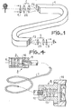
- the light image transport device comprises, in known manner, the ordered bundle of optical fibers 1, an optical input device 2 and an optical output lens 3.
- the optical axes ZE and ZS of objectives 2 and 3 are perpendicular to the plane end faces of the optical cable 1, respectively to the input face FE and to the output face FS.
- Objective 2 focuses the scene observed on the plane of the FE face. In the case of an outdoor scene, a landscape as shown, the incident radiation can be considered to be formed by parallel rays focused by optics 2 on the plane FE.
- the light image is reproduced identically on the output side on the face FS since the cable is ordered, that is to say that the ends of each fiber are positioned in the same way in x and in y on the faces FE and FS respectively.
- the optical objective 3 disposed downstream of the exit face FS makes it possible to take up the light radiation conducted by the cable 1 ending at the exit face to transmit the corresponding image towards use; in the case under consideration the exit optics 3 ensures, in reverse to that of entry, the passage in parallel rays for a visual observation of the radiation scattered by each fiber end of the plane FS.
- a prism of triangular section 4 is introduced at the input upstream of the optic 2 according to the conventional name, and an analog prism 5 on the outlet side downstream of the optics 3.
- white light or polychromic light is broken down by the prism according to its various lines; it is the phenomenon of dispersion due to the fact that the index of the glass depends on the color, therefore on the wavelength, and the deviations inflicted are different according to the wavelengths received.
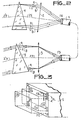
- the red radiations R are less deviated than the green Vs which are themselves less deviated than the blue B, as shown in FIG. 2.
- This dispersion property is used according to the invention to produce at the input images relating to the different lengths of waves shifted in the FE plane.
- Fig. 3 shows, by exaggerating the difference, such a situation.
- the red IR image will be produced in AIBICIDI, the green image IV in A2B2C2D2, and the blue image IB in A3B3C3D3.
- images IV and IB have been intentionally moved to the front of the FE input face.
- the image of a point will be formed according to an extent DL corresponding to the spectral dispersion produced by the prism, and the radiations contributing to form the image of a point will now be transported simultaneously by several fibers.
- FB optics and not just one.
- Fig. 2 illustrates the operation.
- the displacement DL of a point of the image, due to the dispersion, occurs in a plane orthogonal to the edge of the prism 4, such as the plane of the figure.
- the edge is also parallel to the entry face FE and perpendicular to the optical axis ZE to which the entry direction Z'E corresponds as a result of the deviation.
- the prism 5 has the same response of refractive index as a function of the wavelength and it is therefore made of the same material as the element 4; its arrangement must also be homologous with that of prism 4, that is to say that the edge of prism 5 is parallel to the face FS and orthogonal to the direction of the dispersion (direction A1-A3, BI-B3, etc., Fig. 3).
- the angle at the top of the prism 5 is the same as that of the prism 4 if the focal lengths fl and f2 of the optics 2 and 3 are equal, otherwise it is equal to fl / f2 times the angle of the input prism.
- the apex angle A of the prisms must remain limited if we do not want to exceed a distortion threshold compatible with the desired optical quality.
- the angle A is chosen to be small, around 10 °, and the glass can be an existing glass with a refractive index of 1.8 for the sodium line and having a dispersion with an index of 0 , 32 across the visible spectrum.
- the assembly is such that the dispersion DL at the FE face covers more than one fiber; the DL value will be determined in relation to the dimensions of an elementary bundle which generally reaches five to seven times the diameter of a fiber.
- Fig. 4 relates to a possible use for taking pictures of video images, in particular of television.
- the terminal part FE input side of the cable 1 and the optical elements 2 and 4 are mounted together with mechanical parts 10 and 11 which support them and ensure their respective positioning.
- the assembly A thus formed is small, light, easy to handle by an operator operating at a distance from the camera situated at the other end at B.
- This second part likewise comprises the optical elements 3 and 5 in a structure mechanical 12, 13 integral with the housing 14 of the camera symbolized by the end of its tube 15, such as a vidicon, and its associated optics 17. This focuses the parallel radiation at the outlet of the prism 15 to reform the image of the field observed on the photoreceptor target 16 of the tube.
Landscapes
- Physics & Mathematics (AREA)
- General Physics & Mathematics (AREA)
- Optics & Photonics (AREA)
- Optical Fibers, Optical Fiber Cores, And Optical Fiber Bundles (AREA)
- Instruments For Viewing The Inside Of Hollow Bodies (AREA)
- Optical Elements Other Than Lenses (AREA)
Applications Claiming Priority (2)
| Application Number | Priority Date | Filing Date | Title |
|---|---|---|---|
| FR8108344A FR2504758A1 (fr) | 1981-04-27 | 1981-04-27 | Dispositif de transport d'image lumineuse par cable optique et utilisation pour la prise de vues d'images video |
| FR8108344 | 1981-04-27 |
Publications (2)
| Publication Number | Publication Date |
|---|---|
| EP0064899A2 true EP0064899A2 (de) | 1982-11-17 |
| EP0064899A3 EP0064899A3 (de) | 1983-06-15 |
Family
ID=9257816
Family Applications (1)
| Application Number | Title | Priority Date | Filing Date |
|---|---|---|---|
| EP82400695A Withdrawn EP0064899A3 (de) | 1981-04-27 | 1982-04-16 | Einrichtung zur Übertragung von Bildern mittels eines optischen Kabels und Verwendung bei einer Videokamera |
Country Status (3)
| Country | Link |
|---|---|
| EP (1) | EP0064899A3 (de) |
| JP (1) | JPS57185003A (de) |
| FR (1) | FR2504758A1 (de) |
Cited By (7)
| Publication number | Priority date | Publication date | Assignee | Title |
|---|---|---|---|---|
| EP0134930A1 (de) * | 1983-06-30 | 1985-03-27 | Hitachi, Ltd. | Vorrichtung zur optischen Bildübertragung |
| FR2569278A1 (fr) * | 1984-08-14 | 1986-02-21 | Thomson Csf | Dispositif de transport d'image par cable optique |
| FR2581459A1 (fr) * | 1985-05-03 | 1986-11-07 | Thomson Csf | Dispositif de transport et de combinaison d'images lumineuses, et son utilisation pour un viseur de casque |
| US4676593A (en) * | 1983-04-18 | 1987-06-30 | Asahi Kogaku Kogyo Kabushiki Kaisha | Eyepiece and photographing device for fiberscope |
| EP0275947A3 (de) * | 1987-01-20 | 1989-05-03 | Honeywell Inc. | Bildverstärker für faseroptisches Transmissionssystem |
| DE4417762C1 (de) * | 1994-05-20 | 1995-10-12 | Juergen Prof Dr Med Lamprecht | Vorrichtung und Verfahren zum Projizieren und Empfangen von Bildinformation mittels eines Bildschirms |
| CN105929483A (zh) * | 2015-07-10 | 2016-09-07 | 黄得锋 | 一种单束可传像光纤及其应用 |
Families Citing this family (2)
| Publication number | Priority date | Publication date | Assignee | Title |
|---|---|---|---|---|
| CN106291922A (zh) * | 2016-10-24 | 2017-01-04 | 广东技术师范学院 | 全息镜像传输系统 |
| US10953797B2 (en) * | 2018-04-05 | 2021-03-23 | Toyota Motor Engineering & Manufacturing North America, Inc. | Cloaking devices with converging lenses and coherent image guides and vehicles comprising the same |
Family Cites Families (3)
| Publication number | Priority date | Publication date | Assignee | Title |
|---|---|---|---|---|
| US449037A (en) * | 1891-03-24 | Wood-screw | ||
| DE1165303B (de) * | 1960-07-09 | 1964-03-12 | Optische Ind Iade Oude Delftia | Optisches Bilduebertragungssystem |
| US3328594A (en) * | 1965-11-26 | 1967-06-27 | Edward E Sheldon | Inspecting apparatus using fiber optics |
-
1981
- 1981-04-27 FR FR8108344A patent/FR2504758A1/fr not_active Withdrawn
-
1982
- 1982-04-16 EP EP82400695A patent/EP0064899A3/de not_active Withdrawn
- 1982-04-26 JP JP57070184A patent/JPS57185003A/ja active Pending
Cited By (11)
| Publication number | Priority date | Publication date | Assignee | Title |
|---|---|---|---|---|
| US4676593A (en) * | 1983-04-18 | 1987-06-30 | Asahi Kogaku Kogyo Kabushiki Kaisha | Eyepiece and photographing device for fiberscope |
| EP0134930A1 (de) * | 1983-06-30 | 1985-03-27 | Hitachi, Ltd. | Vorrichtung zur optischen Bildübertragung |
| FR2569278A1 (fr) * | 1984-08-14 | 1986-02-21 | Thomson Csf | Dispositif de transport d'image par cable optique |
| EP0178195A1 (de) * | 1984-08-14 | 1986-04-16 | Thomson-Csf | Bildübertragung mittels eines optischen Kabels |
| FR2581459A1 (fr) * | 1985-05-03 | 1986-11-07 | Thomson Csf | Dispositif de transport et de combinaison d'images lumineuses, et son utilisation pour un viseur de casque |
| EP0202987A1 (de) * | 1985-05-03 | 1986-11-26 | Thomson-Csf | Bildleitungs- und -kombinationsvorrichtung und ihre Anwendung in einem Helmsichtgerät |
| US4735473A (en) * | 1985-05-03 | 1988-04-05 | Thomson-Csf | Device for optical-cable transport and combination of light images |
| EP0275947A3 (de) * | 1987-01-20 | 1989-05-03 | Honeywell Inc. | Bildverstärker für faseroptisches Transmissionssystem |
| DE4417762C1 (de) * | 1994-05-20 | 1995-10-12 | Juergen Prof Dr Med Lamprecht | Vorrichtung und Verfahren zum Projizieren und Empfangen von Bildinformation mittels eines Bildschirms |
| US5530495A (en) * | 1994-05-20 | 1996-06-25 | Lamprecht; Juergen | Apparatus and method for projecting and receiving image information using a screen |
| CN105929483A (zh) * | 2015-07-10 | 2016-09-07 | 黄得锋 | 一种单束可传像光纤及其应用 |
Also Published As
| Publication number | Publication date |
|---|---|
| FR2504758A1 (fr) | 1982-10-29 |
| JPS57185003A (en) | 1982-11-15 |
| EP0064899A3 (de) | 1983-06-15 |
Similar Documents
| Publication | Publication Date | Title |
|---|---|---|
| EP0202987B1 (de) | Bildleitungs- und -kombinationsvorrichtung und ihre Anwendung in einem Helmsichtgerät | |
| EP0162493B1 (de) | Fernrohr mit zwei Vergrösserungen | |
| FR2461966A1 (fr) | Accouplement demontable permettant le couplage d'une paire de fibres photoconductrices | |
| GB2148026A (en) | Dichroic beam splitter | |
| EP0064899A2 (de) | Einrichtung zur Übertragung von Bildern mittels eines optischen Kabels und Verwendung bei einer Videokamera | |
| US10627310B2 (en) | Imaging system for multi-fiber connector inspection | |
| JP4574229B2 (ja) | 広角レンズ装置、カメラおよびプロジェクタ | |
| EP1208401B1 (de) | Vorrichtung zur erzeugung spektroskopischer bilder | |
| JP2582144B2 (ja) | 撮影レンズ | |
| EP0111351B1 (de) | Binokularlupe | |
| US5608833A (en) | Focal-plane detector imaging system with improved optical damage threshold | |
| JPS6396618A (ja) | 撮像装置 | |
| JP2004513386A (ja) | 有限な直径の開口部を通してのみ接近可能な遠隔物体の画像を提供するための装置 | |
| JPH10510638A (ja) | ビデオ画像の画素を照射するために設けられ、光導波路に入射される拡散の小さい光束を伝送するための方法及び装置 | |
| US5644122A (en) | Grin optical system | |
| CN210605257U (zh) | 一种光学接收装置及光学测量装置 | |
| JPH0219818A (ja) | 暗視双眼鏡 | |
| Brodie et al. | Multi-object spectroscopy at UCO/Lick Observatory | |
| WO2025133484A1 (fr) | Tube intensificateur d'images couleur et dispositif de vision nocturne en couleur associe | |
| EP0503558B1 (de) | Einrichtung zur Sichtbarmachung des Kerns einer Glasfaser | |
| JP2025010792A (ja) | 測定用光学系及び測光測色装置 | |
| WO2022265495A1 (en) | Image capturing device and method for capturing an image | |
| EP0574325A1 (de) | Übersichtsvorrichtung mit Weitwinkelobjektiv für totale Raumüberwachung | |
| FR2698700A1 (fr) | Dispositif optique de calibration pour caméra thermique. | |
| Jenkins et al. | The fibre-fed spectrograph for the 4.2-metre William Herschel Telescope |
Legal Events
| Date | Code | Title | Description |
|---|---|---|---|
| PUAI | Public reference made under article 153(3) epc to a published international application that has entered the european phase |
Free format text: ORIGINAL CODE: 0009012 |
|
| AK | Designated contracting states |
Designated state(s): DE GB IT NL SE |
|
| PUAL | Search report despatched |
Free format text: ORIGINAL CODE: 0009013 |
|
| AK | Designated contracting states |
Designated state(s): DE GB IT NL SE |
|
| 17P | Request for examination filed |
Effective date: 19831201 |
|
| STAA | Information on the status of an ep patent application or granted ep patent |
Free format text: STATUS: THE APPLICATION IS DEEMED TO BE WITHDRAWN |
|
| 18D | Application deemed to be withdrawn |
Effective date: 19841102 |
|
| RIN1 | Information on inventor provided before grant (corrected) |
Inventor name: REYMOND, JEAN-CLAUDE |