EP0064954A2 - Methode zum Regeln eines Reibungs- oder Fixierelements und Geräte dafür - Google Patents
Methode zum Regeln eines Reibungs- oder Fixierelements und Geräte dafür Download PDFInfo
- Publication number
- EP0064954A2 EP0064954A2 EP82810197A EP82810197A EP0064954A2 EP 0064954 A2 EP0064954 A2 EP 0064954A2 EP 82810197 A EP82810197 A EP 82810197A EP 82810197 A EP82810197 A EP 82810197A EP 0064954 A2 EP0064954 A2 EP 0064954A2
- Authority
- EP
- European Patent Office
- Prior art keywords
- friction
- tool head
- segments
- thread
- dental
- Prior art date
- Legal status (The legal status is an assumption and is not a legal conclusion. Google has not performed a legal analysis and makes no representation as to the accuracy of the status listed.)
- Withdrawn
Links
- 238000000034 method Methods 0.000 title claims description 12
- 230000014759 maintenance of location Effects 0.000 claims description 23
- 230000009849 deactivation Effects 0.000 claims description 2
- 230000004913 activation Effects 0.000 claims 1
- 230000003213 activating effect Effects 0.000 abstract description 3
- 238000001994 activation Methods 0.000 description 1
- 238000000605 extraction Methods 0.000 description 1
Images


Classifications
-
- A—HUMAN NECESSITIES
- A61—MEDICAL OR VETERINARY SCIENCE; HYGIENE
- A61C—DENTISTRY; APPARATUS OR METHODS FOR ORAL OR DENTAL HYGIENE
- A61C13/00—Dental prostheses; Making same
-
- A—HUMAN NECESSITIES
- A61—MEDICAL OR VETERINARY SCIENCE; HYGIENE
- A61C—DENTISTRY; APPARATUS OR METHODS FOR ORAL OR DENTAL HYGIENE
- A61C13/00—Dental prostheses; Making same
- A61C13/225—Fastening prostheses in the mouth
-
- A—HUMAN NECESSITIES
- A61—MEDICAL OR VETERINARY SCIENCE; HYGIENE
- A61C—DENTISTRY; APPARATUS OR METHODS FOR ORAL OR DENTAL HYGIENE
- A61C3/00—Dental tools or instruments
-
- A—HUMAN NECESSITIES
- A61—MEDICAL OR VETERINARY SCIENCE; HYGIENE
- A61C—DENTISTRY; APPARATUS OR METHODS FOR ORAL OR DENTAL HYGIENE
- A61C8/00—Means to be fixed to the jaw-bone for consolidating natural teeth or for fixing dental prostheses thereon; Dental implants; Implanting tools
- A61C8/0089—Implanting tools or instruments
Definitions
- attachments are used, such as anchors, slides or bars, which may be provided with one or more friction or retention elements.
- the latter may consist of a body of cylindrical or cylindrical-conical shape, one part of which is hollowed out and segmented and the other of which has a tapped hole in the axis and in the extension of the first.
- the hollowed out and segmented part is intended to be inserted into a counter body. The more the segment or segments which it has or which make it up, the greater its friction or retention force in the counter body. On the contrary, the tighter the said segment (s), the more its friction or retention force in the counter body will be weak.
- a certain force of friction or retention of the body pre-described in its counter-body is obviously necessary to ensure the holding of the prosthesis in the mouth.
- this force is notably limited by physiological data, for example by the resistance of natural teeth to the extraction force.
- it is also limited by the very fact of the prosthesis whose proper functioning must be ensured, that is to say which must be able to be put in place and easily removed. It is generally considered that the said friction or retention force is between 600gr minimum and 800gr maximum.
- the repeated placement and removal of the prosthesis causes wear of the friction or retention element which jeopardizes the holding of the prosthesis in the mouth.
- the invention aims to overcome these drawbacks.
- the tool head successively carries a thread on a rod as well as a conical pivot.
- the tool head successively carries a thread on a rod as well as a hollow cone.
- Fig. 1 is a partial cross-sectional view and a partial front view of a friction element.
- Fig. 2 is a top view of the friction element according to FIG. 1.
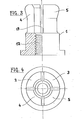
- Fig. 3 is a partial cross-sectional view and a partial front view of a retention element.
- Fig. 4 is a top view of the retention element according to FIG. 3.
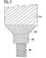
- Fig. 5 is a cross-sectional view of the tool for implementing the method of activating the friction or retention element.
- Fig. 6 is a cross-sectional view of the tool for implementing the method for deactivating the friction element.
- the friction element of fig. 1 just like the retention element of FIG. 3 consists of a body 1, the upper part of which is hollowed out and comprises several segments, that is, respectively the segments 6, 7, 8, 9, 10, 11 according to FIGS. 1 and 2 and 2, 3, 4, 5 according to fig. 3 and 4.
- the segmented part of the friction element according to FIG. 1 and the retention element according to FIG. 3 is intended to be inserted in a body not shown.
- the body 1 according to FIGS. 1 and 3 has a threaded hole 12 located precisely in the extension and in the axis of the recess 13 of its upper part.
- a tool head comprising successively a thread 14 on a rod 15 and a conical pivot 16 so that the threaded part 14 of the tool head ends up screw into the tapped hole 12 and its conical pivot 16 comes to bear on the inner edges of the segments 6, 7, 8, 9, 10, 11 according to figs. 1 and 2 and 2, 3, 4, 5 depending on the fig. 3 and 4.
- the friction or retention force of the body 1 in its counter-body will be increased proportionally. Any mark on the tool head will allow the user to count the number of turns printed on it.
- a tool head comprising successively a thread 17 on a rod 18 and a hollow cone 19 so that the threaded part 17 of the tool head ends up screw into the tapped hole 12 and its hollow cone 19 comes to bear on the outer edges of the segments 6, 7, 8, 9, 10, 11 according to FIGS. 1 and 2 and 2, 3, 4, 5 according to fig. 3 and 4.
- the friction or retention force of the body 1 in its counter-body will be reduced proportionally. Any mark on the tool head will also allow the user to count the number of turns printed on it.
- the practitioner has simple and effective means to ensure and control at all times the holding of the prosthesis in the mouth according to each particular case.
Landscapes
- Health & Medical Sciences (AREA)
- Oral & Maxillofacial Surgery (AREA)
- Dentistry (AREA)
- Epidemiology (AREA)
- Life Sciences & Earth Sciences (AREA)
- Animal Behavior & Ethology (AREA)
- General Health & Medical Sciences (AREA)
- Public Health (AREA)
- Veterinary Medicine (AREA)
- Dental Tools And Instruments Or Auxiliary Dental Instruments (AREA)
Applications Claiming Priority (2)
| Application Number | Priority Date | Filing Date | Title |
|---|---|---|---|
| CH309981 | 1981-05-13 | ||
| CH3099/81 | 1981-05-13 |
Publications (2)
| Publication Number | Publication Date |
|---|---|
| EP0064954A2 true EP0064954A2 (de) | 1982-11-17 |
| EP0064954A3 EP0064954A3 (de) | 1984-08-29 |
Family
ID=4248595
Family Applications (1)
| Application Number | Title | Priority Date | Filing Date |
|---|---|---|---|
| EP82810197A Withdrawn EP0064954A3 (de) | 1981-05-13 | 1982-05-11 | Methode zum Regeln eines Reibungs- oder Fixierelements und Geräte dafür |
Country Status (1)
| Country | Link |
|---|---|
| EP (1) | EP0064954A3 (de) |
Family Cites Families (3)
| Publication number | Priority date | Publication date | Assignee | Title |
|---|---|---|---|---|
| US3495432A (en) * | 1967-06-12 | 1970-02-17 | David E Benson | Flaring tool |
| US4182152A (en) * | 1977-09-08 | 1980-01-08 | Westinghouse Electric Corporation | Grid sleeve bulge tool |
| CH621255A5 (de) * | 1978-03-29 | 1981-01-30 | Cendres & Metaux Sa |
-
1982
- 1982-05-11 EP EP82810197A patent/EP0064954A3/de not_active Withdrawn
Also Published As
| Publication number | Publication date |
|---|---|
| EP0064954A3 (de) | 1984-08-29 |
Similar Documents
| Publication | Publication Date | Title |
|---|---|---|
| US5839896A (en) | Dental post extractor apparatus | |
| EP0748188B1 (de) | Mittel zum befestigen eines elementes an einem zahnimplantat | |
| US5322443A (en) | Method and means for affixing a component to a dental implant | |
| KR101718464B1 (ko) | 임플란트용 어버트먼트 제거 장치 | |
| EP0501255A1 (de) | Instrumentensatz zum Bohren von Zahnwurzelkanälen | |
| EP0800796A1 (de) | Schaubgerät mit Schraubenmagazin, insbesondere für die Gesichts- und Kieferchirurgie | |
| EP0608216A1 (de) | Dentales mehrkomponenten implantat | |
| WO1995014437A1 (fr) | Implant pour dispositif d'osteosynthese, notamment du rachis et instrument correspondant de pose | |
| SE446594B (sv) | Tandstift for fastsettning i en tandrotskanal | |
| US10820936B2 (en) | Pedicle screw removal tool and method of use | |
| CH689997A5 (fr) | Jeu de forets pour l'alésage de la partie coronaire des canaux radiculaires dentaires. | |
| US3471929A (en) | Dental instrument | |
| CH685280A5 (fr) | Instrument pour l'art dentaire servant au traitement des canaux radiculaires. | |
| JPS58221940A (ja) | 伝動工具 | |
| CA2903922A1 (fr) | Instrument endodontique, notamment pour l'alesage d'un canal radiculaire. | |
| EP1155662A1 (de) | Übertragungselement für Zahnprothesen | |
| US3430345A (en) | Holder for dentist's instruments | |
| FR2737847A1 (fr) | Implant-taraud comprimant | |
| JP2010137052A (ja) | 歯インプラントの結合ねじの、ねじ基部を除去する器具 | |
| EP2383059A1 (de) | Spanabhebendes Werkzeug und Zange mit austauschbarem Ansatzstück | |
| KR100923275B1 (ko) | 치과용 뼈 절단공구 | |
| EP0020261B1 (de) | Zange zum konzentrischen Spannen | |
| KR102423053B1 (ko) | 임플란트용 어버트먼트 제거 장치 | |
| EP0305934A1 (de) | Zahnstift | |
| FR2848096A1 (fr) | Implant dentaire cylindrique intra-osseux a insertion laterale et dispositif de guidage pour la mise en place de cet implant |
Legal Events
| Date | Code | Title | Description |
|---|---|---|---|
| PUAI | Public reference made under article 153(3) epc to a published international application that has entered the european phase |
Free format text: ORIGINAL CODE: 0009012 |
|
| AK | Designated contracting states |
Designated state(s): AT BE DE FR GB IT NL SE |
|
| PUAL | Search report despatched |
Free format text: ORIGINAL CODE: 0009013 |
|
| RHK1 | Main classification (correction) |
Ipc: A61C 13/22 |
|
| AK | Designated contracting states |
Designated state(s): AT BE DE FR GB IT NL SE |
|
| STAA | Information on the status of an ep patent application or granted ep patent |
Free format text: STATUS: THE APPLICATION IS DEEMED TO BE WITHDRAWN |
|
| 18D | Application deemed to be withdrawn |
Effective date: 19850503 |
|
| RIN1 | Information on inventor provided before grant (corrected) |
Inventor name: GUGLIELMETTI, SILVIO |