EP0065047A1 - Système de traitement d'eau usée utilisant des moyens d'aération et de circulation - Google Patents
Système de traitement d'eau usée utilisant des moyens d'aération et de circulation Download PDFInfo
- Publication number
- EP0065047A1 EP0065047A1 EP19810302223 EP81302223A EP0065047A1 EP 0065047 A1 EP0065047 A1 EP 0065047A1 EP 19810302223 EP19810302223 EP 19810302223 EP 81302223 A EP81302223 A EP 81302223A EP 0065047 A1 EP0065047 A1 EP 0065047A1
- Authority
- EP
- European Patent Office
- Prior art keywords
- liquid
- partition
- channel
- partition means
- waste water
- Prior art date
- Legal status (The legal status is an assumption and is not a legal conclusion. Google has not performed a legal analysis and makes no representation as to the accuracy of the status listed.)
- Ceased
Links
- 238000004065 wastewater treatment Methods 0.000 title claims abstract description 8
- 238000005273 aeration Methods 0.000 title description 17
- 239000007788 liquid Substances 0.000 claims abstract description 67
- 238000005192 partition Methods 0.000 claims abstract description 62
- 238000005276 aerator Methods 0.000 claims abstract description 60
- 239000010802 sludge Substances 0.000 claims abstract description 33
- 238000004891 communication Methods 0.000 claims abstract description 20
- 239000002351 wastewater Substances 0.000 claims description 16
- 238000000926 separation method Methods 0.000 claims description 3
- 230000033001 locomotion Effects 0.000 description 10
- 238000000034 method Methods 0.000 description 7
- 230000008569 process Effects 0.000 description 7
- 239000010865 sewage Substances 0.000 description 7
- 230000009471 action Effects 0.000 description 5
- 238000005086 pumping Methods 0.000 description 5
- 230000006378 damage Effects 0.000 description 4
- 230000009467 reduction Effects 0.000 description 4
- 241000894006 Bacteria Species 0.000 description 3
- QVGXLLKOCUKJST-UHFFFAOYSA-N atomic oxygen Chemical compound [O] QVGXLLKOCUKJST-UHFFFAOYSA-N 0.000 description 3
- 238000000354 decomposition reaction Methods 0.000 description 3
- 230000001066 destructive effect Effects 0.000 description 3
- 244000005700 microbiome Species 0.000 description 3
- 229910052760 oxygen Inorganic materials 0.000 description 3
- 239000001301 oxygen Substances 0.000 description 3
- 238000013459 approach Methods 0.000 description 2
- 230000008901 benefit Effects 0.000 description 2
- 238000013461 design Methods 0.000 description 2
- 238000002347 injection Methods 0.000 description 2
- 239000007924 injection Substances 0.000 description 2
- 239000000463 material Substances 0.000 description 2
- 150000002823 nitrates Chemical class 0.000 description 2
- 239000005416 organic matter Substances 0.000 description 2
- 239000008213 purified water Substances 0.000 description 2
- XLYOFNOQVPJJNP-UHFFFAOYSA-N water Chemical compound O XLYOFNOQVPJJNP-UHFFFAOYSA-N 0.000 description 2
- 229910002651 NO3 Inorganic materials 0.000 description 1
- NHNBFGGVMKEFGY-UHFFFAOYSA-N Nitrate Chemical compound [O-][N+]([O-])=O NHNBFGGVMKEFGY-UHFFFAOYSA-N 0.000 description 1
- 230000001580 bacterial effect Effects 0.000 description 1
- 230000015572 biosynthetic process Effects 0.000 description 1
- 238000006243 chemical reaction Methods 0.000 description 1
- 238000005352 clarification Methods 0.000 description 1
- 238000010276 construction Methods 0.000 description 1
- 238000011109 contamination Methods 0.000 description 1
- 230000007423 decrease Effects 0.000 description 1
- 238000007599 discharging Methods 0.000 description 1
- 230000000694 effects Effects 0.000 description 1
- 230000002452 interceptive effect Effects 0.000 description 1
- 230000014759 maintenance of location Effects 0.000 description 1
- 238000006213 oxygenation reaction Methods 0.000 description 1
- 238000000746 purification Methods 0.000 description 1
- 238000012216 screening Methods 0.000 description 1
- 238000004062 sedimentation Methods 0.000 description 1
- 239000000126 substance Substances 0.000 description 1
Images
Classifications
-
- C—CHEMISTRY; METALLURGY
- C02—TREATMENT OF WATER, WASTE WATER, SEWAGE, OR SLUDGE
- C02F—TREATMENT OF WATER, WASTE WATER, SEWAGE, OR SLUDGE
- C02F3/00—Biological treatment of water, waste water, or sewage
- C02F3/02—Aerobic processes
- C02F3/12—Activated sludge processes
- C02F3/1236—Particular type of activated sludge installations
- C02F3/1257—Oxidation ditches
-
- C—CHEMISTRY; METALLURGY
- C02—TREATMENT OF WATER, WASTE WATER, SEWAGE, OR SLUDGE
- C02F—TREATMENT OF WATER, WASTE WATER, SEWAGE, OR SLUDGE
- C02F3/00—Biological treatment of water, waste water, or sewage
- C02F3/02—Aerobic processes
- C02F3/12—Activated sludge processes
- C02F3/14—Activated sludge processes using surface aeration
- C02F3/16—Activated sludge processes using surface aeration the aerator having a vertical axis
-
- Y—GENERAL TAGGING OF NEW TECHNOLOGICAL DEVELOPMENTS; GENERAL TAGGING OF CROSS-SECTIONAL TECHNOLOGIES SPANNING OVER SEVERAL SECTIONS OF THE IPC; TECHNICAL SUBJECTS COVERED BY FORMER USPC CROSS-REFERENCE ART COLLECTIONS [XRACs] AND DIGESTS
- Y02—TECHNOLOGIES OR APPLICATIONS FOR MITIGATION OR ADAPTATION AGAINST CLIMATE CHANGE
- Y02W—CLIMATE CHANGE MITIGATION TECHNOLOGIES RELATED TO WASTEWATER TREATMENT OR WASTE MANAGEMENT
- Y02W10/00—Technologies for wastewater treatment
- Y02W10/10—Biological treatment of water, waste water, or sewage
Definitions
- the present invention relates to a flowing liquid system and more particularly to such a system provided with novel means for simultaneously aerating, mixing and circulating the liquid at predetermined rates for optimum process results.
- the sludge flocs should remain suspended in the reactor but should settle readily in a clarifier (settling tank) from which all or a portion can be easily returned to the reservoir while purified water is drawn off.
- a sludge floc can typically achieve an average age of 30 to 40 days and carries strong, well-developed bacteria and micro-organisms which are active in converting the organic matter in the waste water into products which are environmentally harmless or easily precipitated or otherwise removed.
- This "activated sludge" is maintained in the reactor by returning to the reactor at least a portion of the sludge recovered from the underflow of the clarifier. The separation and recirculation of the activated sludge to the reactor for further aeration with the waste water results in the continuous purification of the waste water and causes the treated liquid output from the overflow of the clarifier to be substantially purified.
- Activated sludge treatment plants have as indicated been constructed and have been found to function more or less successfully. However, certain design criteria have been established in the operation of these plants and must be incorporated in any design for efficient operation. It has been found, for example, that the rate of flow of the waste water in the reactor must be maintained at a minimum of 0.8 to 1.0 feet per second in order to prevent the sludge from settling in, and thereby obstructing, the reactor. It has also been established that it takes from 8 to 12 minutes for the bacteria and other micro-organisms to use up substantially all the dissolved oxygen in the waste water. Energy efficiency considerations, therefore, require that the waste water be subjected to aeration no more often than approximately once every 8 to 12 minutes.
- a continuous waste water treatment system comprising a reactor providing a single, closed, continuous, substantially horizontal path through at least two adjacent substantially concentric loops, each of said loops having a beginning and an end, said reactor being provided with waste water inlet means, treated liquid outlet means, and aeration and circulation means, and wherein the said treated liquid outlet means is connected to clarifying means which removes at least some of the sludge carried by the treated liquid and sludge return means is provided to return at least some of the removed sludge to the said reactor.
- U.S. Patent No. 3,510,110 discloses means whereby a surface aerator may be used in an activated sludge closed circuit waste water treatment system, according to which the oxygen required for the aeration is added by means of a surface aerator rotating about a vertical axis in mandatory association with a partition situated in the vicinity of the said surface aerator and substantially closing off the said circuit on one side of the said surface aerator.
- a surface aerator rotating about a vertical axis in mandatory association with a partition situated in the vicinity of the said surface aerator and substantially closing off the said circuit on one side of the said surface aerator.
- Another object of the invention is the provision of such a system comprising aeration and circulation means which avoid or substantially reduce the amount of floc destruction referred to above.
- Yet another object of the invention is the provision of improved and/or more efficient aerating and circulating means for use in a horizontally disposed flowing liquid system, when a high degree of aeration is required together with a strong propulsion force to move the liquid horizontally at the required speed in the circuit as for example in activated sludge waste water treatment systems, and especially in such systems as mentioned above where long distances are required between points of aeration in the circuit and where the circuit path is often curved.
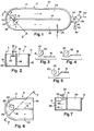
- reference numeral 10 indicates generally an apparatus embodying my invention comprising a reservoir or reactor 12 which includes an outside wall 14, an inside wall 16, partition means 18 and surface aerator means 20 with a substantially vertical axis or shaft means 22.
- Waste water to be treated enters a first channel 23 in the reactor 12 through inlet means 24 and flows past the partition means 18 into a communication section 26 wherein the surface aerator means 20 co-operating with the partition means 18 simultaneously aerates and by a unique centrifugal pumping action, impels the waste water into a second channel 28.
- Outlet means 30 for the treated liquid such as an overflow pipe, is provided which removes treated liquid to a clarifying means 32 in the form of a settling tank.
- the clarifying means 32 is provided with an outlet pipe 34 for removing purified water (effluent) from the system, and a sludge pipe 36 which leads to a sludge pump 38 which is connected by a sludge return pipe 40 back to the reactor 12 and by a pipe 42 to an excess sludge tank 44.
- the surface aerator means 20 which may be of known configuration, is positioned in the communication section 26 in such manner that the axis 22 is separated from the partition means 18 by a distance "a" corresponding to about 1.5 to 2 radii of the said surface aerator means 20.
- the dimensions of the communication section 26 and the diameter of the surface aerator means 20 are so selected that the axis 22 is separated from the oustide wall of the said communication section 26 by a distance "b" corresponding to more than 2 radii of the said surface aerator means 20.
- the lateral deflection of the incoming flow toward the outside wall 14 causes the flow to follow the surface of the outside wall 14 (which is curved as shown but which may instead be composed of a plurality of segmented substantially vertical planar sections) in the communication section 26 and thereby merge with the flow around the surface aerator means 20 at a relatively greater distance from the surface aerator means 20 where the rate of flow is slower, which acts to reduce turbulence even further.
- This reduction in turbulence allows the liquid to carry more energy from the surface aerator means in the form of rotational motion than would be possible in the presence of increased energy wasting turbulence, and this increase in energy in the form of rotational motion increases the centrifugal pumping action of the surface aerator means 20.
Landscapes
- Life Sciences & Earth Sciences (AREA)
- Biodiversity & Conservation Biology (AREA)
- Microbiology (AREA)
- Hydrology & Water Resources (AREA)
- Engineering & Computer Science (AREA)
- Environmental & Geological Engineering (AREA)
- Water Supply & Treatment (AREA)
- Chemical & Material Sciences (AREA)
- Organic Chemistry (AREA)
- Aeration Devices For Treatment Of Activated Polluted Sludge (AREA)
Priority Applications (1)
| Application Number | Priority Date | Filing Date | Title |
|---|---|---|---|
| EP19810302223 EP0065047A1 (fr) | 1981-05-19 | 1981-05-19 | Système de traitement d'eau usée utilisant des moyens d'aération et de circulation |
Applications Claiming Priority (1)
| Application Number | Priority Date | Filing Date | Title |
|---|---|---|---|
| EP19810302223 EP0065047A1 (fr) | 1981-05-19 | 1981-05-19 | Système de traitement d'eau usée utilisant des moyens d'aération et de circulation |
Publications (1)
| Publication Number | Publication Date |
|---|---|
| EP0065047A1 true EP0065047A1 (fr) | 1982-11-24 |
Family
ID=8188309
Family Applications (1)
| Application Number | Title | Priority Date | Filing Date |
|---|---|---|---|
| EP19810302223 Ceased EP0065047A1 (fr) | 1981-05-19 | 1981-05-19 | Système de traitement d'eau usée utilisant des moyens d'aération et de circulation |
Country Status (1)
| Country | Link |
|---|---|
| EP (1) | EP0065047A1 (fr) |
Cited By (2)
| Publication number | Priority date | Publication date | Assignee | Title |
|---|---|---|---|---|
| JPS60136800U (ja) * | 1984-02-18 | 1985-09-11 | 難波 丈治 | 循環式曝気槽 |
| GB2160192A (en) * | 1984-06-16 | 1985-12-18 | Whitehead & Poole | Aeration tank |
Citations (7)
| Publication number | Priority date | Publication date | Assignee | Title |
|---|---|---|---|---|
| US3510110A (en) * | 1967-07-03 | 1970-05-05 | Dwars Ing Bureau | Sewage purification |
| US3620512A (en) * | 1969-04-03 | 1971-11-16 | Passavant Werke | Aerating apparatus |
| US3900394A (en) * | 1972-06-06 | 1975-08-19 | Activox Inc | Process for total sewage treatment |
| US4062911A (en) * | 1975-08-27 | 1977-12-13 | Landustrie Sneek Machinefabriek Elektrotechniek B.V. | Device for the purification of waste water |
| DE2706078A1 (de) * | 1977-02-12 | 1978-08-17 | Basf Ag | Vorrichtung zur erhoehung der stroemungsgeschwindigkeit in umlaufgraeben von klaeranlagen |
| US4146478A (en) * | 1976-10-20 | 1979-03-27 | Activox, Inc. | Closed spiral path waste water treatment system |
| DE2751845A1 (de) * | 1977-11-19 | 1979-05-23 | Boehnke Botho | Anlage fuer die biologische abwasseraufbereitung |
-
1981
- 1981-05-19 EP EP19810302223 patent/EP0065047A1/fr not_active Ceased
Patent Citations (7)
| Publication number | Priority date | Publication date | Assignee | Title |
|---|---|---|---|---|
| US3510110A (en) * | 1967-07-03 | 1970-05-05 | Dwars Ing Bureau | Sewage purification |
| US3620512A (en) * | 1969-04-03 | 1971-11-16 | Passavant Werke | Aerating apparatus |
| US3900394A (en) * | 1972-06-06 | 1975-08-19 | Activox Inc | Process for total sewage treatment |
| US4062911A (en) * | 1975-08-27 | 1977-12-13 | Landustrie Sneek Machinefabriek Elektrotechniek B.V. | Device for the purification of waste water |
| US4146478A (en) * | 1976-10-20 | 1979-03-27 | Activox, Inc. | Closed spiral path waste water treatment system |
| DE2706078A1 (de) * | 1977-02-12 | 1978-08-17 | Basf Ag | Vorrichtung zur erhoehung der stroemungsgeschwindigkeit in umlaufgraeben von klaeranlagen |
| DE2751845A1 (de) * | 1977-11-19 | 1979-05-23 | Boehnke Botho | Anlage fuer die biologische abwasseraufbereitung |
Cited By (2)
| Publication number | Priority date | Publication date | Assignee | Title |
|---|---|---|---|---|
| JPS60136800U (ja) * | 1984-02-18 | 1985-09-11 | 難波 丈治 | 循環式曝気槽 |
| GB2160192A (en) * | 1984-06-16 | 1985-12-18 | Whitehead & Poole | Aeration tank |
Similar Documents
| Publication | Publication Date | Title |
|---|---|---|
| US4446018A (en) | Waste treatment system having integral intrachannel clarifier | |
| US5616240A (en) | Device for sewage clarification | |
| US4054514A (en) | Sedimentation apparatus with flocculating feed well | |
| US3470092A (en) | System for the purification of waste waters | |
| US4421648A (en) | Apparatus and a method for biological treatment of waste waters | |
| EP0191483A2 (fr) | Procédé et dispositif pour le traitement biologique aérobie d'eau usée | |
| US4146478A (en) | Closed spiral path waste water treatment system | |
| GB2075856A (en) | Waste treatment system | |
| US4269709A (en) | Waste water treatment system with aeration and circulation means | |
| US5316668A (en) | Wastewater treatment plant and apparatus | |
| EP0526853B1 (fr) | Système de commande de vitesse dans un fossé d'oxydation | |
| US4512895A (en) | Pumpless clarifier apparatus and process for operation thereof in combination with a draft tube circulator/aerator | |
| US4816157A (en) | Hydraulic sweep clarifier | |
| US5567319A (en) | High capacity single tank water clarification method | |
| US6719911B2 (en) | Apparatus and method for the treatment of a contaminated fluid | |
| US3560379A (en) | Method and apparatus for treating water | |
| US4175041A (en) | Apparatus for degassing floating sludge | |
| US4859327A (en) | Means for water and wastewater treatment | |
| EP0065047A1 (fr) | Système de traitement d'eau usée utilisant des moyens d'aération et de circulation | |
| US2969225A (en) | Detention and mixing apparatus for treating waste liquids | |
| US3977974A (en) | Suspended sludge scraper for arcuate sedimentation zone | |
| US20030183572A1 (en) | Activated sludge method and device for the treatment of effluent with nitrogen and phosphorus removal | |
| US4353800A (en) | Method and an apparatus for biological treatment of waste waters | |
| US4202762A (en) | Process and device for the aeration of waste water | |
| CA1051132A (fr) | Installation de sedimentation et floculateur |
Legal Events
| Date | Code | Title | Description |
|---|---|---|---|
| PUAI | Public reference made under article 153(3) epc to a published international application that has entered the european phase |
Free format text: ORIGINAL CODE: 0009012 |
|
| AK | Designated contracting states |
Designated state(s): AT BE CH DE FR GB IT NL SE |
|
| 17P | Request for examination filed |
Effective date: 19830517 |
|
| STAA | Information on the status of an ep patent application or granted ep patent |
Free format text: STATUS: THE APPLICATION HAS BEEN REFUSED |
|
| 18R | Application refused |
Effective date: 19840802 |