EP0065061A2 - Frein de voie à piston hydraulique pour ralentir des wagons de chemin de fer - Google Patents
Frein de voie à piston hydraulique pour ralentir des wagons de chemin de fer Download PDFInfo
- Publication number
- EP0065061A2 EP0065061A2 EP82100054A EP82100054A EP0065061A2 EP 0065061 A2 EP0065061 A2 EP 0065061A2 EP 82100054 A EP82100054 A EP 82100054A EP 82100054 A EP82100054 A EP 82100054A EP 0065061 A2 EP0065061 A2 EP 0065061A2
- Authority
- EP
- European Patent Office
- Prior art keywords
- damper
- bearing
- piston
- hydraulic
- rail
- Prior art date
- Legal status (The legal status is an assumption and is not a legal conclusion. Google has not performed a legal analysis and makes no representation as to the accuracy of the status listed.)
- Granted
Links
Images


Classifications
-
- B—PERFORMING OPERATIONS; TRANSPORTING
- B61—RAILWAYS
- B61K—AUXILIARY EQUIPMENT SPECIALLY ADAPTED FOR RAILWAYS, NOT OTHERWISE PROVIDED FOR
- B61K7/00—Railway stops fixed to permanent way; Track brakes or retarding apparatus fixed to permanent way; Sand tracks or the like
- B61K7/02—Track brakes or retarding apparatus
- B61K7/025—Retarders of the mushroom type
Definitions
- the piston rod is designed like a hook that projects over the mushroom-shaped head of the hydraulic unit. If necessary, the pneumatic cylinder can retract via the piston rod provided with a hook and lower the hydraulic unit of the piston brake against the lifting force of the hydraulic unit.
- This construction is extremely voluminous and constructively complex and is therefore to be rejected for this reason alone. It must be borne in mind that such a construction would be exposed to the harsh operating conditions in railway operation in all weather conditions, and is therefore very maintenance-intensive, and with an effort that can no longer be represented.
- a hydraulic piston rail brake according to the invention has a lowering device which can be extremely simple, for. B. as a one-sided hydraulic piston-cylinder unit that supports the damper. For example, by loading this piston-cylinder unit, the damper can be brought into its effective position, that is, upwards, while the damper is lowered when the hydraulic fluid is drained, so that the wagon wheel remains unaffected.
- a lowering device can be arranged coaxially to the damper, that is, below it, so that the entire device, that is to say hydraulic piston track brake with lowering device, is extremely compact.
- the connecting lines of the piston-cylinder units of the bearing shut-off devices are assigned.
- the individual bearings can be lowered to different degrees.
- the braking effect of the hydraulic piston rail brakes can also be changed.
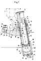
- the reference numeral 1 designates a wheel of a railroad car, not shown, which rolls on a conventional rail 2 with a vertical web 3 and foot 4.
- the reference numeral 5 designates the wheel flange of the wheel 1, which presses a head 6 of a hydraulic piston rail brake 7 downwards, that is to say centrally in the direction X, against a hydraulic damping force.
- the valves provided in the piston rail brake correspond to conventional designs of such hydraulic piston rail brakes and are therefore not necessary for understanding the invention and have therefore not been shown.
- the dampers 7 can be designed to be adjustable with regard to the response speed of the cars, so that only the so-called good runners are detected and braked by the dampers 7, while the bad runners are decelerated less or not at all.
- the speed and spacing of the railroad cars, not shown, can thus be regulated.
- each of the dampers 7 consists of two telescopically, ie variable in length; mutually guided telescopic parts 8, 9, which form a piston-cylinder unit. These telescopic parts 8 and 9 also take up the hydraulic damping medium and the valve devices, which also does not appear from the drawing.
- this head 6 has an approximately lenticular shape and is given an upward, approximately convex configuration by chamfering. In the embodiments according to FIGS. 1 and 2, this head 6 engages in a guide tube 12 and is coupled to it by means of a thread 13, but is detachable.
- the guide tube 12 also runs coaxially to the telescopic parts 8 and 9 and ends at a certain length distance - with the damper 7 pushed together - before the end of the telescopic part 9. As a result, the guide tube 12 moves together with the head 6 and the telescopic part 8 in the axial longitudinal direction of the damper 7.
- FIG. 1 shows in dashed lines the depressed damper 7, while the upper position of the damper 7, shown in full lines, shows the installed state in which the damper 7 is not acted on by a wheel 1.
- the telescopic parts 8 and 9 and the guide tube 12 are arranged coaxially in a bearing tube 14, which is assigned a lowering device 16 at its end facing the ground 15, which extends coaxially to the longitudinal axis of the damper 7 and thus also coaxially to the other tubes, which in the each will be described below.
- This lowering device 16 serves at the same time for mounting the damper 7 via a space hinge 17.
- This space hinge is formed in the embodiment shown in the drawing by a spherical cap which is firmly connected to the end face of the telescopic part 9 and rests in a shape-adapted bearing recess of the lowering device 16 .
- the guide tube 12 is guided in a longitudinally displaceable and tilt-free manner via two spaced-apart slide bearing rings 18 and 18a fastened in the bearing tube 14.
- a wiper seal 19 is arranged in the bearing tube 14 at the front, upper end of the bearing tube 14, which leads on the outer, cylindrical outer surface of the guide tube 12.
- the telescopic part 9, which is larger in diameter, can also be arranged at the top, while the telescopic part 8 is at the bottom, that is, where the telescopic part 9 is arranged in FIGS. 1 and 2.
- the space joint 17 instead of - as shown in Figures 1 and 2 - to be arranged below, above, z. B. in head 6 even articulated, z. B. in that the head 6 is made of a rubber-like elastomer.
- a space joint at the top and bottom that is in the area of the head 6 and in the area of the lowering device 16, in order to rule out tilting of the telescopic parts 8 and 9 when the force is applied eccentrically.
- the head 6 is advantageously arranged rotatably, so that when the wheel flange 5 strikes, the head can rotate as desired in both directions.
- the reference numeral 20 denotes a retaining tab, which has a bearing surface 21, which runs parallel to the underside of the foot 4 and on which the foot 4 rests.
- An upwardly open bearing or a bearing pan 22 is integrally connected to the retaining tab 20 in terms of material, on which the bearing tube 14 rests with an annular shoulder 24 with the interposition of a spacer ring 23.
- the bearing 22 has a cylindrical passage opening 25 through which the bearing tube 14 extends.
- a clamping projection 26 is connected, which is equipped with a bevel 27 adapted to the foot 4, which rests as much as possible on a corresponding bevel of the foot 4.
- a recess 28 is provided between the support surface 21 and the bearing 22, in which a part of the foot 4 of the rail 2 engages in a form-fitting manner.
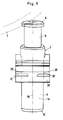
- the holding tab 20 engages on the side opposite the bearing 22 so far beyond the foot area there that there is space for two through holes arranged at a distance from one another in the longitudinal direction of the rail 2, of which only one - 29 - can be seen from FIG. 2, while of the other through hole 30 in FIG. 5 only the center line was illustrated.
- the reference symbol of the through hole concerned was assigned to this center line.
- a screw engages through the through bores 29 and 30, of which only the screw 31 is illustrated in FIGS. 1 and 2. These screws each have a hammer-like head 32, which is positively inserted from below into a corresponding depression in the through hole 29 or 30 concerned and is thereby secured against rotation.
- a clamping piece 33 engages against the neck of the retaining tab 20 and against the adjacent foot part 4, so that after tightening the nuts 34 of the screws 31, the hydraulic piston rail brake is connected to the rail 2 by clamping, that is to say non-positively.
- the longitudinal axis 35 of the damper 7 extends at an acute angle to the longitudinal axis 36 of the rail 2.
- the head 6 can be reinforced in all cases or also made of steel. Furthermore, a shock absorbing body made of rubber or an elastomer with rubber-like properties can be provided under the head 6 in order to dampen noise.
- a bearing piston 41 is guided in a longitudinally displaceable and sealing manner, which on its side facing the telescopic part 9 has a concave recess 42 corresponding to the space joint 17, in which the spherical cap of the space joint 17 rests, so that the hydraulic damper between the head 6 and Bearing piston 41 is supported.
- the end face 40 forms a stop for the bearing piston 41 during its axial displacement in the direction Y, while the displacement path of the bearing piston 41 in the opposite direction X is limited by a welded end wall 43.
- This end wall has a central connection opening 44 with a connection fitting 45 for supplying a suitable pressure medium, in particular hydraulic fluid, into the cylinder space 46 via the feed line 47.
- the annular shoulder 39 which forms the stop for the bearing piston 41 in the direction of displacement Y, is formed by a circlip which is arranged in the inner cylinder wall of the bearing tube 14.
- a further difference from the embodiment according to FIG. 1 can be seen in the fact that the bearing tube 14 and the short tube piece 37 are made in one piece in terms of material, such that the bearing tube 40 has been extended downwards by an amount which is approximately the axial length of the tube piece 37 corresponds.
- the bearing piston 41 abuts the upper stop, that is to say the annular shoulder 39. This is ensured by the pressure medium pressure, in particular hydraulic pressure, prevailing in the cylinder space 46.
- the cylinder chamber 46 is filled with pressure oil via the feed line 47 and by a shut-off element, not shown, for. B. shut off by a slide which is arranged in the feed line 47.
- the piston track brake 7 is ready to brake again when the cylinder chamber 41 is filled with pressure oil from a central hydraulic supply by actuation of the shut-off element, not shown, which results in a corresponding displacement of the bearing piston 41 in the Y direction up to the annular shoulder 39. This also raises the telescopic parts 8 and 9 until the hydraulic damper has returned to its functional position.
- a larger number of hydraulic piston rail brakes 7 are connected to a feed line 47.
- the number may be much greater than from F ig. 4 emerges.
- a central, electromagnetic shut-off device 48 which can be controlled from a central switching point ! can, e.g. B. the entire group of piston rail brakes connected to the supply line 47 are relieved of pressure such that the inflow to a tank 49 is released. If the piston track brakes are rolled over by wheels, the dampers together with the bearing pistons 41 - as described above - are moved downward. The pressure oil in the relevant cylinder chamber 46 is displaced into the feed line 47. This can result in the pressure oil pushing another bearing piston 41 upwards, that is to say in the Y direction, so that the individual dampers change their position in accordance with the rollover process. If several hydraulic dampers are rolled over or this is the path of least resistance for the pressure oil, it also flows off to the storage tank 49.
- a suitable pressure medium source in particular a motor-driven pump, is connected to line 50.
- the reference numeral 51 denotes a so-called entry group of tracks, while 52 denotes a discharge hill and 53 the so-called distribution zone, which is followed by a direction group of tracks at 54.
- Hydraulic piston track brakes with lowering devices are preferably arranged at the beginning of the directional tracks 54.
Landscapes
- Engineering & Computer Science (AREA)
- Mechanical Engineering (AREA)
- Braking Arrangements (AREA)
Priority Applications (1)
| Application Number | Priority Date | Filing Date | Title |
|---|---|---|---|
| AT82100054T ATE10078T1 (de) | 1981-05-19 | 1982-01-07 | Hydraulische kolbengleisbremse zum abbremsen von eisenbahnwagen. |
Applications Claiming Priority (2)
| Application Number | Priority Date | Filing Date | Title |
|---|---|---|---|
| DE3119861A DE3119861C2 (de) | 1981-05-19 | 1981-05-19 | Hydraulische Kolbengleisbremse zum Abbremsen von Eisenbahnwagen |
| DE3119861 | 1981-05-19 |
Publications (3)
| Publication Number | Publication Date |
|---|---|
| EP0065061A2 true EP0065061A2 (fr) | 1982-11-24 |
| EP0065061A3 EP0065061A3 (en) | 1982-12-29 |
| EP0065061B1 EP0065061B1 (fr) | 1984-10-31 |
Family
ID=6132678
Family Applications (1)
| Application Number | Title | Priority Date | Filing Date |
|---|---|---|---|
| EP82100054A Expired EP0065061B1 (fr) | 1981-05-19 | 1982-01-07 | Frein de voie à piston hydraulique pour ralentir des wagons de chemin de fer |
Country Status (3)
| Country | Link |
|---|---|
| EP (1) | EP0065061B1 (fr) |
| AT (1) | ATE10078T1 (fr) |
| DE (2) | DE3119861C2 (fr) |
Cited By (3)
| Publication number | Priority date | Publication date | Assignee | Title |
|---|---|---|---|---|
| DE3604113A1 (de) * | 1986-02-10 | 1987-08-13 | Siemens Ag | Einrichtung zum steuern der geschwindigkeit von eisenbahnfahrzeugen in rangieranlagen |
| GB2199919A (en) * | 1987-01-20 | 1988-07-20 | Nat Supply Co | Landing device |
| WO1999030950A1 (fr) * | 1997-12-13 | 1999-06-24 | Tiefenbach Gmbh | Ensemble frein de voie |
Families Citing this family (2)
| Publication number | Priority date | Publication date | Assignee | Title |
|---|---|---|---|---|
| US4535872A (en) * | 1981-10-06 | 1985-08-20 | Dowty Hydraulic Units Limited | Retarders suitable for wagon speed control and having means for holding them in their operative condition |
| DE102016212654A1 (de) * | 2016-07-12 | 2018-01-18 | Stabilus Gmbh | Gleisbremsdämpfer |
Family Cites Families (8)
| Publication number | Priority date | Publication date | Assignee | Title |
|---|---|---|---|---|
| FR847462A (fr) * | 1938-06-16 | 1939-10-10 | Brasseur | Système de freinage et éventuellement d'arrêt des berlines ou autres véhicules circulant sur voie ferrée |
| DE1183530B (de) * | 1960-05-01 | 1964-12-17 | Dowty Mining Equipment Ltd | Steuereinrichtung zum Beeinflussen der Geschwindigkeit frei laufender Schienenfahrzeuge |
| DE1605349A1 (de) * | 1967-02-28 | 1971-03-11 | Kloeckner Werke Ag | Einrichtung zum Regeln der Geschwindigkeit von rollenden Eisenbahnwagen |
| DE1937113A1 (de) * | 1969-07-22 | 1971-02-04 | Konrad Grebe | Steuereinrichtung zum Beeinflussen der Geschwindigkeit von freilaufenden Schienenfahrzeugen |
| FR2063733A5 (fr) * | 1969-10-29 | 1971-07-09 | Bourcier De Carbon Chris | |
| GB1380900A (en) * | 1970-12-29 | 1975-01-15 | Girling Ltd | Suspension systems |
| GB1462045A (en) * | 1973-02-28 | 1977-01-19 | Dowty Mining Equipment Ltd | Railway wagon speed control means |
| GB2032028B (en) * | 1978-06-22 | 1983-02-02 | Clarke C W | Rail-mounted hydraulic retarder |
-
1981
- 1981-05-19 DE DE3119861A patent/DE3119861C2/de not_active Expired
-
1982
- 1982-01-07 EP EP82100054A patent/EP0065061B1/fr not_active Expired
- 1982-01-07 DE DE8282100054T patent/DE3261081D1/de not_active Expired
- 1982-01-07 AT AT82100054T patent/ATE10078T1/de active
Cited By (3)
| Publication number | Priority date | Publication date | Assignee | Title |
|---|---|---|---|---|
| DE3604113A1 (de) * | 1986-02-10 | 1987-08-13 | Siemens Ag | Einrichtung zum steuern der geschwindigkeit von eisenbahnfahrzeugen in rangieranlagen |
| GB2199919A (en) * | 1987-01-20 | 1988-07-20 | Nat Supply Co | Landing device |
| WO1999030950A1 (fr) * | 1997-12-13 | 1999-06-24 | Tiefenbach Gmbh | Ensemble frein de voie |
Also Published As
| Publication number | Publication date |
|---|---|
| ATE10078T1 (de) | 1984-11-15 |
| DE3261081D1 (en) | 1984-12-06 |
| EP0065061A3 (en) | 1982-12-29 |
| DE3119861A1 (de) | 1982-12-09 |
| EP0065061B1 (fr) | 1984-10-31 |
| DE3119861C2 (de) | 1984-04-05 |
Similar Documents
| Publication | Publication Date | Title |
|---|---|---|
| DE102011113561A1 (de) | Hubkielvorrichtung | |
| DE2344691A1 (de) | Federspeicherzylinder, insbesondere fuer schienenfahrzeug-druckluftbremsanlagen | |
| DE8808519U1 (de) | Hydraulischer Stahlgrubenstempel | |
| DE1605307A1 (de) | Bremsenmontage fuer das rollende Material von Eisenbahnen | |
| DE3236340A1 (de) | Gleisbremse zum abbremsen von eisenbahnwagen | |
| DE1920311U (de) | Vorrichtung fur fahrzeug mit hydraulischen bremsen zur veranderung der bremskraft auf die fahrzeugraeder in abhangigkeit von der radlast. | |
| EP0065061B1 (fr) | Frein de voie à piston hydraulique pour ralentir des wagons de chemin de fer | |
| DE1058854B (de) | Daempfungsvorrichtung fuer Stoesse grosser Amplitude fuer die Achsaufhaengung von Fahrzeugen | |
| DE2507337C2 (de) | Steuervorrichtung zur Beeinflussung der Geschwindigkeit von freilaufenden Schienenfahrzeugen | |
| DE1934482A1 (de) | Eisenbahnwagen | |
| EP0046199B1 (fr) | Frein de voie hydraulique à piston pour le freinage de véhicules ferroviaires | |
| DE3533216C2 (fr) | ||
| DE102004034105A1 (de) | Stützvorrichtung für Anhänger | |
| DE8114838U1 (de) | Hydraulische kolbengleisbremse zum abbremsen von eisenbahnwagen | |
| DE9006739U1 (de) | Gleichlaufvorrichtung für eine Hebebühne | |
| EP0049446B1 (fr) | Frein de voie à piston hydraulique pour freiner des véhicules ferroviaires | |
| DE3642776A1 (de) | Stapelfahrzeug mit einem schwenkbar gelagerten hubgeruest | |
| DE2255435A1 (de) | Vorrichtung zum schleifen von schienen | |
| DE2120593C3 (de) | Bremseinrichtung, insbesondere eine hydraulische Handbremse fur Eisenbahnwagen | |
| DE4339670C2 (de) | Verriegelungssystem für Wechselgeräte zur Verwendung bei Lastkraftwagen sowie Element zur Verwendung bei einem derartigen System | |
| DE19526950C1 (de) | Führungseinrichtung für schienengebundene Fahrzeuge | |
| DE3321384C1 (de) | Verfahren zum Abbremsen mit Bremskatzen im untertägigen Steinkohlebergbau und Bremskatze zum Durchführen dieses Verfahrens | |
| DE3540880A1 (de) | Kolben-zylinder-kombination | |
| DE1605221C (de) | Bremssystem, insbesondere fur Schienenfahrzeuge im untertagigen Grubenbetrieb | |
| DE19730743A1 (de) | Straßenfahrzeug |
Legal Events
| Date | Code | Title | Description |
|---|---|---|---|
| PUAI | Public reference made under article 153(3) epc to a published international application that has entered the european phase |
Free format text: ORIGINAL CODE: 0009012 |
|
| PUAL | Search report despatched |
Free format text: ORIGINAL CODE: 0009013 |
|
| 17P | Request for examination filed |
Effective date: 19820115 |
|
| AK | Designated contracting states |
Designated state(s): AT BE CH DE FR GB IT LU NL SE |
|
| AK | Designated contracting states |
Designated state(s): AT BE CH DE FR GB IT LI LU NL SE |
|
| GRAA | (expected) grant |
Free format text: ORIGINAL CODE: 0009210 |
|
| AK | Designated contracting states |
Designated state(s): AT BE CH DE FR GB IT LI LU NL SE |
|
| PG25 | Lapsed in a contracting state [announced via postgrant information from national office to epo] |
Ref country code: SE Effective date: 19841031 Ref country code: NL Effective date: 19841031 Ref country code: IT Free format text: LAPSE BECAUSE OF FAILURE TO SUBMIT A TRANSLATION OF THE DESCRIPTION OR TO PAY THE FEE WITHIN THE PRESCRIBED TIME-LIMIT;WARNING: LAPSES OF ITALIAN PATENTS WITH EFFECTIVE DATE BEFORE 2007 MAY HAVE OCCURRED AT ANY TIME BEFORE 2007. THE CORRECT EFFECTIVE DATE MAY BE DIFFERENT FROM THE ONE RECORDED. Effective date: 19841031 Ref country code: FR Free format text: THE PATENT HAS BEEN ANNULLED BY A DECISION OF A NATIONAL AUTHORITY Effective date: 19841031 Ref country code: BE Effective date: 19841031 |
|
| REF | Corresponds to: |
Ref document number: 10078 Country of ref document: AT Date of ref document: 19841115 Kind code of ref document: T |
|
| REF | Corresponds to: |
Ref document number: 3261081 Country of ref document: DE Date of ref document: 19841206 |
|
| PG25 | Lapsed in a contracting state [announced via postgrant information from national office to epo] |
Ref country code: AT Effective date: 19850107 |
|
| PG25 | Lapsed in a contracting state [announced via postgrant information from national office to epo] |
Ref country code: LU Free format text: LAPSE BECAUSE OF NON-PAYMENT OF DUE FEES Effective date: 19850131 Ref country code: LI Effective date: 19850131 Ref country code: CH Effective date: 19850131 |
|
| NLV1 | Nl: lapsed or annulled due to failure to fulfill the requirements of art. 29p and 29m of the patents act | ||
| PLBE | No opposition filed within time limit |
Free format text: ORIGINAL CODE: 0009261 |
|
| STAA | Information on the status of an ep patent application or granted ep patent |
Free format text: STATUS: NO OPPOSITION FILED WITHIN TIME LIMIT |
|
| EN | Fr: translation not filed | ||
| REG | Reference to a national code |
Ref country code: CH Ref legal event code: PL |
|
| PG25 | Lapsed in a contracting state [announced via postgrant information from national office to epo] |
Ref country code: DE Effective date: 19851001 |
|
| 26N | No opposition filed | ||
| GBPC | Gb: european patent ceased through non-payment of renewal fee | ||
| PG25 | Lapsed in a contracting state [announced via postgrant information from national office to epo] |
Ref country code: GB Effective date: 19881121 |