EP0065093A2 - Coupleur pour guides d'ondes optiques montés dans des manchons, adapté pour coopérer avec un rack - Google Patents
Coupleur pour guides d'ondes optiques montés dans des manchons, adapté pour coopérer avec un rack Download PDFInfo
- Publication number
- EP0065093A2 EP0065093A2 EP82102488A EP82102488A EP0065093A2 EP 0065093 A2 EP0065093 A2 EP 0065093A2 EP 82102488 A EP82102488 A EP 82102488A EP 82102488 A EP82102488 A EP 82102488A EP 0065093 A2 EP0065093 A2 EP 0065093A2
- Authority
- EP
- European Patent Office
- Prior art keywords
- housing
- plug
- pressure
- sleeve
- screw cap
- Prior art date
- Legal status (The legal status is an assumption and is not a legal conclusion. Google has not performed a legal analysis and makes no representation as to the accuracy of the status listed.)
- Granted
Links
- 230000008878 coupling Effects 0.000 title claims abstract description 21
- 238000010168 coupling process Methods 0.000 title claims abstract description 21
- 238000005859 coupling reaction Methods 0.000 title claims abstract description 21
- 230000003287 optical effect Effects 0.000 title abstract description 3
- 239000013307 optical fiber Substances 0.000 claims abstract description 5
- 238000003780 insertion Methods 0.000 claims description 14
- 230000037431 insertion Effects 0.000 claims description 14
- 230000005540 biological transmission Effects 0.000 claims description 3
- 238000005516 engineering process Methods 0.000 abstract description 4
- 238000013459 approach Methods 0.000 description 3
- 230000006835 compression Effects 0.000 description 3
- 238000007906 compression Methods 0.000 description 3
- 239000000835 fiber Substances 0.000 description 3
- 230000005693 optoelectronics Effects 0.000 description 3
- 230000013011 mating Effects 0.000 description 2
Images


Classifications
-
- G—PHYSICS
- G02—OPTICS
- G02B—OPTICAL ELEMENTS, SYSTEMS OR APPARATUS
- G02B6/00—Light guides; Structural details of arrangements comprising light guides and other optical elements, e.g. couplings
- G02B6/24—Coupling light guides
- G02B6/36—Mechanical coupling means
- G02B6/38—Mechanical coupling means having fibre to fibre mating means
- G02B6/3807—Dismountable connectors, i.e. comprising plugs
- G02B6/3873—Connectors using guide surfaces for aligning ferrule ends, e.g. tubes, sleeves, V-grooves, rods, pins, balls
- G02B6/3874—Connectors using guide surfaces for aligning ferrule ends, e.g. tubes, sleeves, V-grooves, rods, pins, balls using tubes, sleeves to align ferrules
-
- G—PHYSICS
- G02—OPTICS
- G02B—OPTICAL ELEMENTS, SYSTEMS OR APPARATUS
- G02B6/00—Light guides; Structural details of arrangements comprising light guides and other optical elements, e.g. couplings
- G02B6/24—Coupling light guides
- G02B6/36—Mechanical coupling means
- G02B6/38—Mechanical coupling means having fibre to fibre mating means
- G02B6/3807—Dismountable connectors, i.e. comprising plugs
- G02B6/381—Dismountable connectors, i.e. comprising plugs of the ferrule type, e.g. fibre ends embedded in ferrules, connecting a pair of fibres
- G02B6/3818—Dismountable connectors, i.e. comprising plugs of the ferrule type, e.g. fibre ends embedded in ferrules, connecting a pair of fibres of a low-reflection-loss type
- G02B6/3821—Dismountable connectors, i.e. comprising plugs of the ferrule type, e.g. fibre ends embedded in ferrules, connecting a pair of fibres of a low-reflection-loss type with axial spring biasing or loading means
-
- G—PHYSICS
- G02—OPTICS
- G02B—OPTICAL ELEMENTS, SYSTEMS OR APPARATUS
- G02B6/00—Light guides; Structural details of arrangements comprising light guides and other optical elements, e.g. couplings
- G02B6/24—Coupling light guides
- G02B6/36—Mechanical coupling means
- G02B6/38—Mechanical coupling means having fibre to fibre mating means
- G02B6/3807—Dismountable connectors, i.e. comprising plugs
- G02B6/3833—Details of mounting fibres in ferrules; Assembly methods; Manufacture
- G02B6/3834—Means for centering or aligning the light guide within the ferrule
- G02B6/3835—Means for centering or aligning the light guide within the ferrule using discs, bushings or the like
-
- G—PHYSICS
- G02—OPTICS
- G02B—OPTICAL ELEMENTS, SYSTEMS OR APPARATUS
- G02B6/00—Light guides; Structural details of arrangements comprising light guides and other optical elements, e.g. couplings
- G02B6/24—Coupling light guides
- G02B6/36—Mechanical coupling means
- G02B6/38—Mechanical coupling means having fibre to fibre mating means
- G02B6/3807—Dismountable connectors, i.e. comprising plugs
- G02B6/3873—Connectors using guide surfaces for aligning ferrule ends, e.g. tubes, sleeves, V-grooves, rods, pins, balls
- G02B6/3882—Connectors using guide surfaces for aligning ferrule ends, e.g. tubes, sleeves, V-grooves, rods, pins, balls using rods, pins or balls to align a pair of ferrule ends
-
- G—PHYSICS
- G02—OPTICS
- G02B—OPTICAL ELEMENTS, SYSTEMS OR APPARATUS
- G02B6/00—Light guides; Structural details of arrangements comprising light guides and other optical elements, e.g. couplings
- G02B6/24—Coupling light guides
- G02B6/36—Mechanical coupling means
- G02B6/38—Mechanical coupling means having fibre to fibre mating means
- G02B6/3807—Dismountable connectors, i.e. comprising plugs
- G02B6/389—Dismountable connectors, i.e. comprising plugs characterised by the method of fastening connecting plugs and sockets, e.g. screw- or nut-lock, snap-in, bayonet type
-
- G—PHYSICS
- G02—OPTICS
- G02B—OPTICAL ELEMENTS, SYSTEMS OR APPARATUS
- G02B6/00—Light guides; Structural details of arrangements comprising light guides and other optical elements, e.g. couplings
- G02B6/24—Coupling light guides
- G02B6/36—Mechanical coupling means
- G02B6/38—Mechanical coupling means having fibre to fibre mating means
- G02B6/3807—Dismountable connectors, i.e. comprising plugs
- G02B6/3897—Connectors fixed to housings, casing, frames or circuit boards
-
- G—PHYSICS
- G02—OPTICS
- G02B—OPTICAL ELEMENTS, SYSTEMS OR APPARATUS
- G02B6/00—Light guides; Structural details of arrangements comprising light guides and other optical elements, e.g. couplings
- G02B6/24—Coupling light guides
- G02B6/42—Coupling light guides with opto-electronic elements
- G02B6/4292—Coupling light guides with opto-electronic elements the light guide being disconnectable from the opto-electronic element, e.g. mutually self aligning arrangements
Definitions
- the invention relates to a coupling device for optical waveguides (LWL) contained in connector pins, consisting of a housing, which is fastened in an opening in a device housing, contains multiple slits and contains a pressure body for receiving the connector pins with at least one screw cap, and a mating housing, which is fastened in a slide-in frame plug pin slidably disposed therein.
- LWL optical waveguides
- a coupling device for LWL in plug with a sleeve-shaped, longitudinally and transversely slotted clamping body and with a housing surrounding this clamping body, in which the clamping body is provided in the area of the longitudinal slot with parallel approaches, the distance from which corresponds to the longitudinal slot width at which one of the approaches is divided by the transverse slot, in which the housing has a continuous recess corresponding to the contour of the clamping body having, having at least in the area of the divided approach, a passing over into the recess and matching with the length of the recess cavity for receiving pressurized bodies, the screw against the clamping body located above the rotational movement of the ends of the clamp body b pressing are ar (DE -GM 79 35 570).
- This coupling device is not intended for plug-in technology, its use would require the insertion of a plug and its attachment by turning a screw cap after inserting a device.
- the housing has a continuous, cylindrical recess suitable for receiving fiber optic ends, furthermore a centrally separated recess for pressure bodies which corresponds to the length of this recess, and in which the recess and the recess are provided by a multiple bent slot connected to one side (DE-GM 80 18 008).
- the invention has for its object to redesign one of the coupling devices mentioned so that it can bridge the relatively large dimensional tolerances customary in plug-in technology without loss of the extremely precise plug guide, and that it can be locked securely by simple insertion. Furthermore, the device should be able to withstand the often somewhat rough handling of plug-in devices without damage.
- the outer surface of the pressure ring is shaped as a spherical zone in the screw cap for the greatest possible freedom of movement.
- the tip of the plug pin, the entrance of the receiving opening in the housing, the inner surface of the pressure ring and the opening of the screw cap are conically shaped.
- a further embodiment of the invention in which the connector pin is freely rotatable in the connector sleeve, has the advantage that all torsional stresses on the fiber optic cable are avoided which could otherwise occur when installing the counter housing in the slide-in frame and when tightening its fastening nut.
- FIG. 1 shows a part of the coupling device arranged in a withdrawable unit. For better illustration, it is shown on a greatly enlarged scale and rotated by 90 ° against the normal position of use.
- An optical fiber 1 coming from the interior of the device with its plastic jacket 2 is contained in a plug 3, the optically perfect end surface of which is accessible at the tip of the plug 3.
- the plug. 3 is inserted into the clampable part 5 of the housing 4.
- the pin 7 is pressed into the housing 4, which in turn causes the pressure elements 8, which are shown here as balls, to compress the clampable part 5 and thus to center and hold the plug 3.
- the housing 4 is fastened with the differently designed screw cap 9 in an opening in the device housing 10.
- the pressure ring 11 In front of the surface of the housing 4 protruding from the device housing 10, the pressure ring 11 is arranged movably within the screw cap 9.
- the pressure ring 11 strikes the cylindrical part of a pressure sleeve, through which the pressure ring 11 is pressed against the pin 7a, which in turn pressures the body 8a for centering and fastening a into the receiving opening 12 used, also later described connector pin causes.
- the outer surface 13 of the pressure ring 11 is shaped as a spherical section in order to ensure the greatest possible mobility of the pressure ring 11 within the screw cap 9.
- the insertion opening 14 of the screw cap 9, through which the already mentioned pressure sleeve is inserted, is conical, as is the insertion opening 15 of the pressure ring 11 and the mouth of the insertion opening 12 of the housing 4.
- This design makes it possible, even when the device housing 10 is inserted at an angle, into the insertion frame to be described later, to securely grasp the aforementioned plug pin and to insert it into the insertion opening 12.
- the centering and clamping function of the pressure bodies 8 and 8a and the clampable part 5 of the housing 4 is described in detail in the prior art and therefore need not be repeated here.
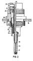
- FIG. 2 shows the part of the coupling device fastened in a slide-in frame or frame, likewise on an enlarged scale and rotated by 90 ° relative to its normal position of use.
- Fig. 3 the entire coupling device is shown on a smaller scale compared to the previous figures in the usual position of use. It can be seen that the plug pin 19 has reached the receiving opening of the housing 4 approximately in the position in which it would meet the mating plug 3, which is now not shown.
- the counter housing 28 has been moved further against the pressure of the spring 23, so that this spring 23 is already compressed and exerts a certain pressure on the tip of the plug pin 19.
- the pressure sleeve 26 is pushed through the screw cap 9 onto the pressure ring 11, which now pushes the pressure elements in the housing 4 together via the pin 7a. Up to this point in time, the plug pin 19 can be freely rotated in the plug sleeve 21. It can also be seen that the device housing 10 can be moved quite a bit towards the counter housing 28 fastened in the insertion frame 16 without any parts being damaged. This is followed by the usual locking in the slide-in frame for slide-in devices.
- FIG. 4 shows an embodiment of the part of the coupling device intended for plug-in devices, in which the receiving opening 4b of the housing 4a has been expanded to such an extent that an optoelectronic component 30 can be accommodated.
- This arrangement is recommended if there are light transmitters or light receivers in the slide-in housing that are to be connected to an optical fiber coming out of the slide-in frame. This saves a plug connection, which further improves the transmission properties of the system.
- the screw cap is not knurled e on its outer surface but smooth and Entry side shown conically, which can be advantageous for certain plug-in types. In such a case, it is advisable to form a slot for screwdrivers on the entry side to securely fasten the screw cap, as also shown.
Landscapes
- Physics & Mathematics (AREA)
- General Physics & Mathematics (AREA)
- Optics & Photonics (AREA)
- Mechanical Coupling Of Light Guides (AREA)
Applications Claiming Priority (2)
| Application Number | Priority Date | Filing Date | Title |
|---|---|---|---|
| DE3119545 | 1981-05-16 | ||
| DE19813119545 DE3119545A1 (de) | 1981-05-16 | 1981-05-16 | Fuer gestelleinschuebe geeignete koppelvorrichtung fuer in steckerstifte gefasste lichtwellenleiter |
Publications (3)
| Publication Number | Publication Date |
|---|---|
| EP0065093A2 true EP0065093A2 (fr) | 1982-11-24 |
| EP0065093A3 EP0065093A3 (en) | 1982-12-29 |
| EP0065093B1 EP0065093B1 (fr) | 1985-10-09 |
Family
ID=6132496
Family Applications (1)
| Application Number | Title | Priority Date | Filing Date |
|---|---|---|---|
| EP82102488A Expired EP0065093B1 (fr) | 1981-05-16 | 1982-03-25 | Coupleur pour guides d'ondes optiques montés dans des manchons, adapté pour coopérer avec un rack |
Country Status (2)
| Country | Link |
|---|---|
| EP (1) | EP0065093B1 (fr) |
| DE (1) | DE3119545A1 (fr) |
Cited By (3)
| Publication number | Priority date | Publication date | Assignee | Title |
|---|---|---|---|---|
| EP0103289A3 (fr) * | 1982-09-13 | 1987-01-07 | Siemens Aktiengesellschaft | Manchon de guidage pour connecteur de guides d'ondes optiques |
| EP0164531B1 (fr) * | 1984-04-18 | 1990-08-08 | Siemens Aktiengesellschaft | Connecteur à fiches pour guides d'ondes lumineuses |
| NL1000295C2 (nl) * | 1994-05-04 | 1997-05-02 | Whitaker Corp | Connector voor een optische vezel. |
Families Citing this family (2)
| Publication number | Priority date | Publication date | Assignee | Title |
|---|---|---|---|---|
| DE3507209A1 (de) * | 1985-03-01 | 1986-09-04 | ANT Nachrichtentechnik GmbH, 7150 Backnang | Steckverbinder fuer lichtwellenleiter |
| DE3729075A1 (de) * | 1987-09-01 | 1989-03-16 | Schmidt Feinmech | Steckverbindung fuer lichtleiter |
Family Cites Families (5)
| Publication number | Priority date | Publication date | Assignee | Title |
|---|---|---|---|---|
| US4158476A (en) * | 1977-12-16 | 1979-06-19 | International Telephone And Telegraph Corporation | Single optical fiber connector |
| DE7817996U1 (de) * | 1978-06-15 | 1978-09-28 | Siemens Ag, 1000 Berlin Und 8000 Muenchen | Lichtwellenleitersteckvorrichtung |
| DE7935570U1 (de) * | 1979-12-18 | 1980-03-20 | Felten & Guilleaume Carlswerk Ag, 5000 Koeln | Koppelvorrichtung mit druckkoerpern fuer in stecker gefasste lichtleitfasern |
| DE8018008U1 (de) * | 1980-07-04 | 1981-03-26 | Philips Kommunikations Industrie AG, 90411 Nürnberg | Koppelvorrichtung für in Stecker gefaßte Lichtwellenleiter |
| DE3025888C2 (de) * | 1980-07-09 | 1985-01-17 | Philips Kommunikations Industrie AG, 8500 Nürnberg | Koppelvorrichtung mit Klemmbrücken für in Stecker gefaßte Lichtleitfasern |
-
1981
- 1981-05-16 DE DE19813119545 patent/DE3119545A1/de active Granted
-
1982
- 1982-03-25 EP EP82102488A patent/EP0065093B1/fr not_active Expired
Cited By (3)
| Publication number | Priority date | Publication date | Assignee | Title |
|---|---|---|---|---|
| EP0103289A3 (fr) * | 1982-09-13 | 1987-01-07 | Siemens Aktiengesellschaft | Manchon de guidage pour connecteur de guides d'ondes optiques |
| EP0164531B1 (fr) * | 1984-04-18 | 1990-08-08 | Siemens Aktiengesellschaft | Connecteur à fiches pour guides d'ondes lumineuses |
| NL1000295C2 (nl) * | 1994-05-04 | 1997-05-02 | Whitaker Corp | Connector voor een optische vezel. |
Also Published As
| Publication number | Publication date |
|---|---|
| DE3119545C2 (fr) | 1990-01-11 |
| EP0065093B1 (fr) | 1985-10-09 |
| EP0065093A3 (en) | 1982-12-29 |
| DE3119545A1 (de) | 1982-12-09 |
Similar Documents
| Publication | Publication Date | Title |
|---|---|---|
| DE69033738T2 (de) | Optischer Stecker-Stift | |
| DE68920272T2 (de) | Optischer Stecker. | |
| DE2512330C3 (de) | Steckverbindung für ummantelte Lichtleitfasern aus Quarzglas oder Glas | |
| DE2853649C2 (fr) | ||
| DE29520445U1 (de) | Vorrichtung zum Anschluß eines Lichtleitkabels an den Lichtleiteranschluß eines Endoskopes | |
| EP0516930B1 (fr) | Dispositif pour connecter des conduites | |
| DE3124546C2 (fr) | ||
| EP0164531B1 (fr) | Connecteur à fiches pour guides d'ondes lumineuses | |
| DE3737842C1 (en) | Optical fibre connector for push-in systems (drawer systems) in telecommunications engineering | |
| DE3517388A1 (de) | Anschlussteil fuer ein faser-optisches kabel | |
| DE102010010018B4 (de) | Steckverbinder für Lichtwellenleiter | |
| DE69116246T2 (de) | Zugentlasteter Stecker für optische Fasern | |
| EP0065093B1 (fr) | Coupleur pour guides d'ondes optiques montés dans des manchons, adapté pour coopérer avec un rack | |
| EP0312147B1 (fr) | Capuchon de protection montable sur une fiche ou sur le couplage d'un connecteur pour guide d'onde lumineuse | |
| DE102013017313B4 (de) | Prüfstiftvorrichtunq, modulares Prüfsystem sowie Sortiment | |
| DE19830148C5 (de) | Anschlußelement für ein Lichtwellenleiterkabel | |
| DE2651768A1 (de) | Verbinder fuer lichtleitkabel und verfahren zur herstellung von anschlusselementen fuer derartige verbinder | |
| DE8114598U1 (de) | Fuer gestelleinschuebe geeignete koppelvorrichtung fuer in steckerstifte gefasste lichtwellenleiter | |
| DE102008019757B4 (de) | Anschlussvorrichtung | |
| DE69102613T2 (de) | Optisches verbindungssystem zur anwendung in der übertragung von video-signalen. | |
| DE3916602C2 (fr) | ||
| DE8221983U1 (de) | Lichtwellenleiter-steckverbinder | |
| EP0898186A1 (fr) | Connecteur pour fibres optiques et cables | |
| EP0463404A1 (fr) | Connecteur pour fibres optiques | |
| DE3220763A1 (de) | Wechseleinrichtung fuer baueinheiten an messgeraeten und werkzeugmaschinen |
Legal Events
| Date | Code | Title | Description |
|---|---|---|---|
| PUAI | Public reference made under article 153(3) epc to a published international application that has entered the european phase |
Free format text: ORIGINAL CODE: 0009012 |
|
| PUAL | Search report despatched |
Free format text: ORIGINAL CODE: 0009013 |
|
| AK | Designated contracting states |
Designated state(s): FR GB IT NL |
|
| AK | Designated contracting states |
Designated state(s): FR GB IT NL |
|
| 17P | Request for examination filed |
Effective date: 19830419 |
|
| ITF | It: translation for a ep patent filed | ||
| GRAA | (expected) grant |
Free format text: ORIGINAL CODE: 0009210 |
|
| AK | Designated contracting states |
Designated state(s): FR GB IT NL |
|
| ITF | It: translation for a ep patent filed | ||
| ET | Fr: translation filed | ||
| PLBE | No opposition filed within time limit |
Free format text: ORIGINAL CODE: 0009261 |
|
| STAA | Information on the status of an ep patent application or granted ep patent |
Free format text: STATUS: NO OPPOSITION FILED WITHIN TIME LIMIT |
|
| 26N | No opposition filed | ||
| PGFP | Annual fee paid to national office [announced via postgrant information from national office to epo] |
Ref country code: NL Payment date: 19870331 Year of fee payment: 6 |
|
| PG25 | Lapsed in a contracting state [announced via postgrant information from national office to epo] |
Ref country code: NL Effective date: 19891001 |
|
| NLV4 | Nl: lapsed or anulled due to non-payment of the annual fee | ||
| PGFP | Annual fee paid to national office [announced via postgrant information from national office to epo] |
Ref country code: FR Payment date: 19920318 Year of fee payment: 11 |
|
| ITTA | It: last paid annual fee | ||
| PGFP | Annual fee paid to national office [announced via postgrant information from national office to epo] |
Ref country code: GB Payment date: 19930301 Year of fee payment: 12 |
|
| PG25 | Lapsed in a contracting state [announced via postgrant information from national office to epo] |
Ref country code: FR Effective date: 19931130 |
|
| REG | Reference to a national code |
Ref country code: FR Ref legal event code: ST |
|
| PG25 | Lapsed in a contracting state [announced via postgrant information from national office to epo] |
Ref country code: GB Effective date: 19940325 |
|
| GBPC | Gb: european patent ceased through non-payment of renewal fee |
Effective date: 19940325 |