EP0065117A2 - Soupape de remplissage se fermant automatiquement - Google Patents
Soupape de remplissage se fermant automatiquement Download PDFInfo
- Publication number
- EP0065117A2 EP0065117A2 EP82103361A EP82103361A EP0065117A2 EP 0065117 A2 EP0065117 A2 EP 0065117A2 EP 82103361 A EP82103361 A EP 82103361A EP 82103361 A EP82103361 A EP 82103361A EP 0065117 A2 EP0065117 A2 EP 0065117A2
- Authority
- EP
- European Patent Office
- Prior art keywords
- pressure
- valve
- tap
- pressure channel
- valve body
- Prior art date
- Legal status (The legal status is an assumption and is not a legal conclusion. Google has not performed a legal analysis and makes no representation as to the accuracy of the status listed.)
- Granted
Links
Images

Classifications
-
- B—PERFORMING OPERATIONS; TRANSPORTING
- B67—OPENING, CLOSING OR CLEANING BOTTLES, JARS OR SIMILAR CONTAINERS; LIQUID HANDLING
- B67D—DISPENSING, DELIVERING OR TRANSFERRING LIQUIDS, NOT OTHERWISE PROVIDED FOR
- B67D7/00—Apparatus or devices for transferring liquids from bulk storage containers or reservoirs into vehicles or into portable containers, e.g. for retail sale purposes
- B67D7/06—Details or accessories
- B67D7/42—Filling nozzles
- B67D7/44—Filling nozzles automatically closing
- B67D7/46—Filling nozzles automatically closing when liquid in container to be filled reaches a predetermined level
- B67D7/465—Electrical probes sensing the level of the liquid
-
- B—PERFORMING OPERATIONS; TRANSPORTING
- B67—OPENING, CLOSING OR CLEANING BOTTLES, JARS OR SIMILAR CONTAINERS; LIQUID HANDLING
- B67C—CLEANING, FILLING WITH LIQUIDS OR SEMILIQUIDS, OR EMPTYING, OF BOTTLES, JARS, CANS, CASKS, BARRELS, OR SIMILAR CONTAINERS, NOT OTHERWISE PROVIDED FOR; FUNNELS
- B67C3/00—Bottling liquids or semiliquids; Filling jars or cans with liquids or semiliquids using bottling or like apparatus; Filling casks or barrels with liquids or semiliquids
- B67C3/02—Bottling liquids or semiliquids; Filling jars or cans with liquids or semiliquids using bottling or like apparatus
- B67C3/22—Details
- B67C3/28—Flow-control devices, e.g. using valves
Definitions
- the invention relates to a tap for filling liquids into containers with automatic termination of the pin after filling, consisting of a valve body which is equipped with an inlet and an outlet nozzle, a valve body arranged in the valve body and actuable by means of a trigger lever for controlling the liquid flow from the inlet to the outlet and a switching device which is connected via a pressure channel to the mouth of the outlet nozzle and which closes the valve depending on the pressure prevailing in the pressure channel.
- Such a filling device is described in DE-OS 26 41 049. It essentially consists of a manually operated flow valve and a vacuum-controlled closing device, by means of which the valve is closed automatically when the container or tank is filled.
- the closing device has a membrane which closes a pressure chamber and which is exposed on the chamber side via a pressure channel to the negative pressure generated by the liquid flow in the valve, while on the other side it is coupled to an element releasably connecting the trigger lever and the valve under spring tension.
- Another pressure channel leads from the pressure chamber to the mouth of the filler neck.
- the pressure-dependent switching device consists of a response to a certain pressure in the pressure channel switching element and a drive element controlled by this, which is coupled to a releasably inserted between the trigger and valve connecting element.
- a advantageous embodiment of the tap according to the invention provides that the pressure-dependent switching element is a pneumatic relay, the output of which is connected to a pneumatic drive element for the working pressure.
- the pressure-dependent switching element is an electro-pneumatic pressure switch and the drive element switched by this is an electromagnet, the armature of which is coupled to the releasable connecting element.
- Figures 1 and 2 show a tap, the structure of which is known in principle with respect to the manually operable flow control and is described for example in DE-OS 26 41 049. It consists of a valve body 1 with an inlet nozzle 2 and an outlet nozzle 3. The inlet is equipped with conventional devices 4 for connecting a feed line, in particular a hose line. The liquid flow from the inlet to the outlet nozzle is controlled by a valve 5, the valve body 6 with its seal 7 is pressed against the valve seat 9 by a compression spring 8. To operate the valve, the valve body is connected to a trigger lever 12 via a linkage 10 and joints 11.
- the linkage consists of a guide tube 13 fastened to the valve body and a pull rod 14 which is connected to the trigger lever via the joints and which is displaceable in the guide tube.
- Guide tube and tension rod are provided with congruent, transversely to the longitudinal axis recesses 15, in which two pins 16 are pressed as a connecting element by means of a drive member against a compression spring 17 so that the movements of the trigger are transmitted to the valve body.
- the pins are fastened in a holder 18 which is also displaceable transversely to the longitudinal axis and is supported on the compression spring 17 resting in a recess 19 of the valve body 1.
- the holder consists of a U-shaped part with bores in the U-legs for receiving the pins, the back of the part being connected to a membrane 21 which closes off a pressure chamber 20 and which together form the drive element for the displacement movements.
- a further tube 25 fastened to the valve body 1 is arranged concentrically around the outlet nozzle at a very short distance, approximately 0.1 mm, so that the annular space of the double jacket tube thus formed forms the pressure channel 24.
- Za p f clars the membrane 21 is acted upon by the relay 22 via the pressure line with compressed air, so that the pins 16 are held against the spring 17 in the recesses 15 of the linkage 10. If the liquid level in the container to be filled exceeds the mouth 23 of the outlet nozzle 3, the air in the pressure channel 24 slightly compressed by the liquid. As a result of the very small volume of the annular space forming the pressure channel and the tube capillary, a pressure increase is associated with this, which is sufficient to switch over the pneumatic relay 22. To increase this pressure increase, the annular gap at the mouth 23 is widened. After switching, the membrane 21 is no longer under pressure, so that the compression spring 17 acting on the holder 18 can push the pins 16 out of the recesses 15. The connection between the guide tube 13 and tension rod 14 is thereby released. The spring 8 engaging the valve body 6 can now press it onto the valve seat 9, after which the valve is in the closed position.
- the relay 22 switches back due to the pressure drop.
- the membrane is then again under pressure, so that the pins 16 are pressed against the linkage 10 and after pushing back the pull rod 14 by the trigger lever 12 in the closed position can snap back into the recesses 15.
- the valve can then be operated again.
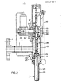
- FIG. 2 shows a further embodiment of the tap according to the invention, in which the pressure-dependent switching device of the tap, which is otherwise unchanged from FIG. 1, consists of a commercially available electro-pneumatic pressure switch 30 and an electromagnet 31 controlled by it.
- the control input of the pressure switch which is attached to the valve body 1, is also connected to the pressure channel 24 via a hose capillary 26. Its electrical output is connected to the coil 32 of the electromagnet, the axially movable armature 33 of which is coupled to the U-shaped holder 18 for the pins 16.
- the compression spring 17 acts "Here on the bracket 18 according to their arrangement in a cylindrical recess 34 of the valve body 1 in the direction of the engagement of the pins in the recesses 15 and is supported on the one hand on the shoulder 35 of the recess 34 and on the other hand on the back of the U-shaped holder.
- the pressure switch 30 When the pressure in the pressure channel 24 increases as a result of the excess liquid level in the container to be filled, the pressure switch 30 is actuated and the coil 32 of the electromagnet 31 is thus connected to the power source. Under the force of the magnetic field of the current-carrying coil, the armature 33 is pulled into it and the holder 18 with the pins 16 is thus removed from the linkage 10. The connection between the guide tube 13 and the pull rod 14 is now released, so that the valve 5 goes into the closed position by means of the spring 8. When the outlet port opening becomes free, the electromagnet 31 is switched off again as a result of the pressure drop in the pressure channel and the valve can be operated again as described above.
- an electromagnet as a drive element has the advantage that large drive forces can be generated in order to overcome higher friction in the valve mechanism - for example as a result of strong valve springs for high sealing forces.
- a development, not shown in the drawing, of the tap described above consists in the pressure channel 24 being connected to a gas pressure source, for example air or nitrogen, via a lateral nipple and a connecting line.
- a gas pressure source for example air or nitrogen
- the gas flowing continuously at the mouth 23 of the outlet nozzle 3 in a very small amount keeps the annular gap from any deposits, for example crystallization products, and from Remains of the tap liquid free. If the mouth is now immersed in the tap liquid, the flow resistance at the annular gap increases and thus the pressure in the pressure channel.
- the pneumatic relay 22 or the electropneumatic pressure switch 30, which are expediently connected directly to the pressure system, for example by a bypass, respond to the pressure increase and cause the valve to close, as already described.
- the switching device 22, 21; 30, 31
- the exhaust air duct 37 shown in FIG. 1 serves to extract the solvent vapors released during filling.
Landscapes
- Engineering & Computer Science (AREA)
- Mechanical Engineering (AREA)
- Loading And Unloading Of Fuel Tanks Or Ships (AREA)
- Filling Of Jars Or Cans And Processes For Cleaning And Sealing Jars (AREA)
Applications Claiming Priority (2)
| Application Number | Priority Date | Filing Date | Title |
|---|---|---|---|
| DE3117669 | 1981-05-05 | ||
| DE19813117669 DE3117669A1 (de) | 1981-05-05 | 1981-05-05 | Zapfhahn mit automatischer abschaltung |
Publications (3)
| Publication Number | Publication Date |
|---|---|
| EP0065117A2 true EP0065117A2 (fr) | 1982-11-24 |
| EP0065117A3 EP0065117A3 (en) | 1983-04-27 |
| EP0065117B1 EP0065117B1 (fr) | 1988-01-13 |
Family
ID=6131456
Family Applications (1)
| Application Number | Title | Priority Date | Filing Date |
|---|---|---|---|
| EP82103361A Expired EP0065117B1 (fr) | 1981-05-05 | 1982-04-21 | Soupape de remplissage se fermant automatiquement |
Country Status (4)
| Country | Link |
|---|---|
| US (1) | US4453577A (fr) |
| EP (1) | EP0065117B1 (fr) |
| DE (2) | DE3117669A1 (fr) |
| ES (1) | ES8304028A1 (fr) |
Cited By (3)
| Publication number | Priority date | Publication date | Assignee | Title |
|---|---|---|---|---|
| FR2643355A1 (fr) * | 1989-02-21 | 1990-08-24 | Cga Hbs | Installation de distribution de carburant pour vehicule |
| FR2839057A1 (fr) * | 2002-04-24 | 2003-10-31 | Regis Emile Ferdinand Raux | Pistolet de remplissage avec arret automatique |
| CN101590993B (zh) * | 2009-03-16 | 2012-09-05 | 杭州中亚机械股份有限公司 | 无菌灌装阀 |
Families Citing this family (1)
| Publication number | Priority date | Publication date | Assignee | Title |
|---|---|---|---|---|
| DE102014106404A1 (de) * | 2014-05-07 | 2015-11-12 | Khs Gmbh | Füllvorrichtung |
Family Cites Families (11)
| Publication number | Priority date | Publication date | Assignee | Title |
|---|---|---|---|---|
| US2209219A (en) * | 1940-07-23 | Automatic cut-off nozzle for | ||
| US2745585A (en) * | 1951-02-20 | 1956-05-15 | Lindars Herman | Automatic filling apparatus for liquid containers |
| US3075563A (en) * | 1961-02-27 | 1963-01-29 | Buckeye Iron & Brass Works | Automatic chemical handling nozzle |
| US3101101A (en) * | 1961-07-31 | 1963-08-20 | Curtiss Wright Corp | System and mechanism for dispensing fluids |
| LU43573A1 (fr) * | 1962-04-19 | 1963-06-17 | ||
| US3196908A (en) * | 1963-03-11 | 1965-07-27 | Emco Wheaton | Nozzle with vacuum operated valve tripping means |
| US3380491A (en) * | 1965-03-26 | 1968-04-30 | Emco Wheaton | Universal electric nozzle |
| BE794068A (fr) * | 1972-01-17 | 1973-07-16 | Volucompteurs Aster Boutillon | Perfectionnements aux embouts de robinets de distribution de liquides a fermeture automatique |
| GB1562494A (en) * | 1975-09-12 | 1980-03-12 | Emco Wheaton | Nozzles |
| DE2551994C3 (de) * | 1975-11-17 | 1980-05-29 | Nalco Chemical Co., Oak Brook, Ill. (V.St.A.) | BehälterfUUvorrichtung |
| US4343336A (en) * | 1978-01-24 | 1982-08-10 | Trygg Lars Erik | Liquid dispensing device |
-
1981
- 1981-05-05 DE DE19813117669 patent/DE3117669A1/de not_active Withdrawn
-
1982
- 1982-04-21 DE DE8282103361T patent/DE3277967D1/de not_active Expired
- 1982-04-21 EP EP82103361A patent/EP0065117B1/fr not_active Expired
- 1982-04-22 US US06/371,013 patent/US4453577A/en not_active Expired - Fee Related
- 1982-05-04 ES ES511913A patent/ES8304028A1/es not_active Expired
Cited By (4)
| Publication number | Priority date | Publication date | Assignee | Title |
|---|---|---|---|---|
| FR2643355A1 (fr) * | 1989-02-21 | 1990-08-24 | Cga Hbs | Installation de distribution de carburant pour vehicule |
| EP0384345A1 (fr) * | 1989-02-21 | 1990-08-29 | Compagnie Generale D'automatisme Cga-Hbs | Installation de distribution de carburant pour véhicule |
| FR2839057A1 (fr) * | 2002-04-24 | 2003-10-31 | Regis Emile Ferdinand Raux | Pistolet de remplissage avec arret automatique |
| CN101590993B (zh) * | 2009-03-16 | 2012-09-05 | 杭州中亚机械股份有限公司 | 无菌灌装阀 |
Also Published As
| Publication number | Publication date |
|---|---|
| EP0065117B1 (fr) | 1988-01-13 |
| US4453577A (en) | 1984-06-12 |
| ES511913A0 (es) | 1983-02-16 |
| EP0065117A3 (en) | 1983-04-27 |
| DE3277967D1 (en) | 1988-02-18 |
| ES8304028A1 (es) | 1983-02-16 |
| DE3117669A1 (de) | 1982-11-25 |
Similar Documents
| Publication | Publication Date | Title |
|---|---|---|
| EP0519507B1 (fr) | Dispositif de vanne, en particulier pour retourner des vapeurs d'essence | |
| DE2944053C2 (fr) | ||
| EP0065117A2 (fr) | Soupape de remplissage se fermant automatiquement | |
| DE2343069A1 (de) | Druckmittelbetaetigbares bodenventil fuer tankwagen | |
| DE9011041U1 (de) | Vollschlauchzapfventil | |
| DE2709796C3 (de) | Vorrichtung zum Versprühen einer Flüssigkeit aus einem geschlossenen Behältnis | |
| DE19951192B4 (de) | Absperrventil für einen Tank | |
| DE2823680A1 (de) | Automatische einfuellvorrichtung fuer tanks u. dgl. | |
| DE60127448T2 (de) | Servogesteuertes sicherheitsventil für behälter für toxische fluide | |
| DE2706439A1 (de) | Hauptabschaltventil fuer schaltbetaetigung von getrieben | |
| AT408970B (de) | Vorrichtung zum verhindern des überfüllens eines kraftstofftankes | |
| DE3304390A1 (de) | Zapfpistole fuer vollschlauch-zapfanlagen | |
| DE102023204902A1 (de) | Tankventilanordnung und Verfahren zum Betanken eines Gasdruckspeichers | |
| EP0246617B1 (fr) | Appareil pour impulsions d'air évitant la formation de voûtes dans les silos pour matières en vrac | |
| DE2834019A1 (de) | Druckregler von druckluftbremsanlagen in kraftfahrzeugen | |
| DE19707400C2 (de) | Vorrichtung zum dosierten Fördern einer Minimalmenge einer Flüssigkeit | |
| AT317767B (de) | Rohrpoststation | |
| EP3974374B1 (fr) | Buse de distribution avec interrupteur entre deux débits maximaux | |
| CH615642A5 (en) | Nebuliser on a liquid container | |
| DE2063723C2 (de) | Selbsttätig schließende Zapfpistole | |
| DE3514442A1 (de) | Ventil fuer einen fluessigkeitskreislauf | |
| DE4313679C1 (de) | Zapfpistole | |
| DE19850561A1 (de) | Einrichtung zum Druckausgleich in einer hydraulischen Anlage | |
| DE3429026A1 (de) | Zapfpistole fuer vollschlauch-zapfanlagen | |
| AT396408B (de) | Einrichtung zur steuerung eines gasdruckreglers |
Legal Events
| Date | Code | Title | Description |
|---|---|---|---|
| PUAI | Public reference made under article 153(3) epc to a published international application that has entered the european phase |
Free format text: ORIGINAL CODE: 0009012 |
|
| AK | Designated contracting states |
Designated state(s): BE CH DE GB SE |
|
| 17P | Request for examination filed |
Effective date: 19821211 |
|
| PUAL | Search report despatched |
Free format text: ORIGINAL CODE: 0009013 |
|
| AK | Designated contracting states |
Designated state(s): BE CH DE GB LI SE |
|
| GRAA | (expected) grant |
Free format text: ORIGINAL CODE: 0009210 |
|
| AK | Designated contracting states |
Kind code of ref document: B1 Designated state(s): BE CH DE GB LI SE |
|
| REF | Corresponds to: |
Ref document number: 3277967 Country of ref document: DE Date of ref document: 19880218 |
|
| GBT | Gb: translation of ep patent filed (gb section 77(6)(a)/1977) | ||
| PLBE | No opposition filed within time limit |
Free format text: ORIGINAL CODE: 0009261 |
|
| STAA | Information on the status of an ep patent application or granted ep patent |
Free format text: STATUS: NO OPPOSITION FILED WITHIN TIME LIMIT |
|
| 26N | No opposition filed | ||
| PGFP | Annual fee paid to national office [announced via postgrant information from national office to epo] |
Ref country code: CH Payment date: 19900323 Year of fee payment: 9 |
|
| PGFP | Annual fee paid to national office [announced via postgrant information from national office to epo] |
Ref country code: SE Payment date: 19900326 Year of fee payment: 9 |
|
| PGFP | Annual fee paid to national office [announced via postgrant information from national office to epo] |
Ref country code: DE Payment date: 19900411 Year of fee payment: 9 |
|
| PGFP | Annual fee paid to national office [announced via postgrant information from national office to epo] |
Ref country code: GB Payment date: 19900417 Year of fee payment: 9 |
|
| PGFP | Annual fee paid to national office [announced via postgrant information from national office to epo] |
Ref country code: BE Payment date: 19900419 Year of fee payment: 9 |
|
| PG25 | Lapsed in a contracting state [announced via postgrant information from national office to epo] |
Ref country code: GB Effective date: 19910421 |
|
| PG25 | Lapsed in a contracting state [announced via postgrant information from national office to epo] |
Ref country code: SE Effective date: 19910422 |
|
| PG25 | Lapsed in a contracting state [announced via postgrant information from national office to epo] |
Ref country code: LI Effective date: 19910430 Ref country code: CH Effective date: 19910430 Ref country code: BE Effective date: 19910430 |
|
| BERE | Be: lapsed |
Owner name: BASF A.G. Effective date: 19910430 |
|
| GBPC | Gb: european patent ceased through non-payment of renewal fee | ||
| REG | Reference to a national code |
Ref country code: CH Ref legal event code: PL |
|
| PG25 | Lapsed in a contracting state [announced via postgrant information from national office to epo] |
Ref country code: DE Effective date: 19920201 |
|
| EUG | Se: european patent has lapsed |
Ref document number: 82103361.0 Effective date: 19911108 |