EP0065151B1 - Régulateur de pression d'air pour les freins de l'essieu avant de véhicules - Google Patents
Régulateur de pression d'air pour les freins de l'essieu avant de véhicules Download PDFInfo
- Publication number
- EP0065151B1 EP0065151B1 EP82103665A EP82103665A EP0065151B1 EP 0065151 B1 EP0065151 B1 EP 0065151B1 EP 82103665 A EP82103665 A EP 82103665A EP 82103665 A EP82103665 A EP 82103665A EP 0065151 B1 EP0065151 B1 EP 0065151B1
- Authority
- EP
- European Patent Office
- Prior art keywords
- pressure
- piston
- braking
- reaction
- brake
- Prior art date
- Legal status (The legal status is an assumption and is not a legal conclusion. Google has not performed a legal analysis and makes no representation as to the accuracy of the status listed.)
- Expired
Links
- 230000000717 retained effect Effects 0.000 claims 1
- 239000003638 chemical reducing agent Substances 0.000 description 4
- 230000000694 effects Effects 0.000 description 2
- 238000013022 venting Methods 0.000 description 2
- 230000001419 dependent effect Effects 0.000 description 1
- 238000010586 diagram Methods 0.000 description 1
- 238000000034 method Methods 0.000 description 1
Images
Classifications
-
- B—PERFORMING OPERATIONS; TRANSPORTING
- B60—VEHICLES IN GENERAL
- B60T—VEHICLE BRAKE CONTROL SYSTEMS OR PARTS THEREOF; BRAKE CONTROL SYSTEMS OR PARTS THEREOF, IN GENERAL; ARRANGEMENT OF BRAKING ELEMENTS ON VEHICLES IN GENERAL; PORTABLE DEVICES FOR PREVENTING UNWANTED MOVEMENT OF VEHICLES; VEHICLE MODIFICATIONS TO FACILITATE COOLING OF BRAKES
- B60T8/00—Arrangements for adjusting wheel-braking force to meet varying vehicular or ground-surface conditions, e.g. limiting or varying distribution of braking force
- B60T8/26—Arrangements for adjusting wheel-braking force to meet varying vehicular or ground-surface conditions, e.g. limiting or varying distribution of braking force characterised by producing differential braking between front and rear wheels
-
- B—PERFORMING OPERATIONS; TRANSPORTING
- B60—VEHICLES IN GENERAL
- B60T—VEHICLE BRAKE CONTROL SYSTEMS OR PARTS THEREOF; BRAKE CONTROL SYSTEMS OR PARTS THEREOF, IN GENERAL; ARRANGEMENT OF BRAKING ELEMENTS ON VEHICLES IN GENERAL; PORTABLE DEVICES FOR PREVENTING UNWANTED MOVEMENT OF VEHICLES; VEHICLE MODIFICATIONS TO FACILITATE COOLING OF BRAKES
- B60T11/00—Transmitting braking action from initiating means to ultimate brake actuator without power assistance or drive or where such assistance or drive is irrelevant
- B60T11/10—Transmitting braking action from initiating means to ultimate brake actuator without power assistance or drive or where such assistance or drive is irrelevant transmitting by fluid means, e.g. hydraulic
- B60T11/28—Valves specially adapted therefor
- B60T11/34—Pressure reducing or limiting valves
Definitions
- the present invention relates to an air pressure regulator or pressure reducer, in particular for controlling the brake pressure of vehicle front axle brake cylinders as a function of the control pressure, which is specified in the preamble of claim 1.
- an air pressure regulator is known from document US-A-3 769 997.
- Air pressure regulators or pressure reducers of this type are also known from document US-A-3 492 052. Your task is to ensure a lower pressure than the control pressure in the braking elements of the front axle of a vehicle at the start of braking. Later, as the braking process progresses, the operating pressure should be equal to the control pressure. This pressure regulation is carried out in order to reduce the wear on the seals and linings of the braking elements during the frequent and less intensive actuation of the brakes of the vehicle, that is to say during the decelerating braking operations.
- the braking elements of the front axle are dimensioned stronger than those of the rear axle, in order to ensure a corresponding braking performance when the driver carries out brisk braking and fully depresses the brake pedal.
- the air pressure regulators or pressure reducers of the type mentioned reduce the pressure applied to the more dimensioned braking members at low values of the control pressure, with correspondingly less wear on the linings.
- the regulators are not effective at strong actuation pressures, that is during brusque braking, so that the pressure acting on the larger dimensioned braking elements is equal to the control pressure, so that effective braking is ensured under these conditions.
- the device rests (in the magazine) and presses on a seal that wears out over time due to the load.
- This type of pressure regulator is also very bulky due to the arrangement of the pistons. It is also more expensive due to the composition of many components.
- the object of the present invention is therefore to provide an air pressure regulator of the type mentioned at the outset, which is simple in design, economically inexpensive and not bulky to build, and which also makes it possible to produce different brake pressures and pressure dependency profiles in the braking members. These properties should also be able to be carried out with elements already forming components of the device. To achieve this object, the design features set out in the characterizing part of claim 1 are provided.
- the elastic member consists of a cylindrical spring which is arranged in the interior of the piston and is preferably without tension in the rest position of the device.
- the largest stroke of the reaction piston and thus the characteristic of the brake pressure of the brake elements involved is changed in the axial direction by adjusting a nozzle which is already provided in the device for venting the air into the open.
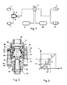
- 1 denotes the brake cylinders of the motor-carrying front axle of a vehicle
- 2 the brake cylinders of the rear axle
- 3 a compressed air distributor and S 1 and S 2 two supply chambers.
- a pressure regulator 4 is connected to the supply circuit of the front axle brake elements 1. The elements of the front axle are monitored and controlled because they have a particularly strong effect on the dynamic forces during braking.
- the braking elements of the front axle are dimensioned more strongly than those of the rear axle; either with respect to the diameter of the brake cylinder or the length of the actuating lever of the brakes.
- the pressure regulator 4 shown in detail in FIG. 2 is provided with a housing 5, which has two connections 6 on the side for the lines to the brake elements 1. In the bottom 7, a pierced nozzle 8 is provided for venting the air outdoors.
- the air pressure regulator 4 is closed at the top with a lid 9, which with a connection 10 is provided, to which the connecting line to the compressed air distributor 3 connects.
- the air pressure regulator 4 contains two separate, axially aligned and movable pistons, namely a control piston 11 and a reaction piston 12, which are separated from each other by means of an elastic member consisting of a cylinder spring 13.
- the spring 13 is mounted on an inner collar in each case inside the pistons 11 and 12 and surrounds a movable valve body 14 which carries the seals 15 and 16 at both ends.
- the first seal 15 cooperates with a seat 17 of the control piston 11, so that an inlet valve (15, 17) results; the second seal 16 interacts with a seat 18 on the connector 8, so that an outlet valve (16, 18) results.
- the cylinder spring 13, which is supported on the two opposite collars of the piston 11 and 12, is de-energized in the rest position of the regulator, while it is compressed in the functional position in order to transmit the loads from one piston to the other, as in the following is explained.
- the reaction piston 12 moves inside the housing 5 when there is an effective seal, and the piston 11 also moves in the housing 5 when there is an effective seal.
- the piston 11 is sealed in the area of the cover 9 and in an extension 11a, on the inside of the piston 12, in the area of the federal government for the cylinder spring 13.
- the upper end face S c of the piston 11, which is exposed to the control pressure, is smaller than the lower end face S r of the piston 12, to which the reaction or counterpressure acts during braking, but larger than the pressure surface S'c of the part 11a from the piston 11, which penetrates into the reaction piston 12.
- the maximum stroke Li that the reaction piston 12 can carry out in the housing 5 is limited by a cover collar 9a of the cover 9, against which the piston abuts.
- This maximum stroke Li determines the maximum of the control pressure P c .
- the control pressure adapts to this.
- the maximum stroke Li can be changed by changing the starting position of the reaction piston 12. This is possible by adjusting the nozzle 8 in the bore 7a, which is recessed at the bottom 7 of the housing 5.
- the connector 8 and the bore 7 are provided with a thread, so that the connector 8 is adjusted by simply turning it. In the desired axial position, the threaded connector 8 is fixed with a nut 19.
- FIG. 3 shows the function of the brake pressure P r as a function of the control pressure P c .
- P r is the pressure at the ports 6 and is therefore also the pressure in the brake cylinders 1.
- P c is the pressure at the inlet port 10. If the regulator 4 is absent, the pressure acting in the brake cylinders 1 is given by the bisector C, which is formed by an initial section C 1, which is drawn in dashed lines for the sake of clarity, and by a further section C 2 , drawn continuously.
- the control pressure P c at the connection 6 of the pressure regulator 3 is equal to the brake pressure in the brake cylinders 1.
- the pressure regulator 4 is connected to the supply circuit of the brake cylinders 1, the braking characteristic is given by the curve C R , which results from the initial section C 3 , a central section C 4 and an end section which coincides with C 2 .
- the air arriving at the inlet connection 10 of the pressure regulator 4 causes the lowering of the moving parts, in connection with the pistons 11 12, when the outlet valve 16, 18 is closed and the inlet valve 15, 17 is opened Lowering of the piston 12 is effected by the spring 13 which is arranged between the two pistons 11 and 12.
- reaction pressure P r proves to be lower than the control pressure P c .
- the piston 12 moves upwards under the load of the spring 13 until it hits the cover collar 9a.
- the course of the reaction pressure P r is represented by the section C 3 of the curve C R.
- This second braking phase is represented by the intermediate section C 4 of the curve C R.
- the maximum stroke of the Piston 12 is enlarged, so that the phase C 3 is also enlarged. If, on the other hand, the nozzle 8 is adjusted inwards, the maximum stroke and the phase C 3 are reduced. Section C 4 always remains parallel to itself; its slope is determined by the ratio of the areas S c and S ' c of the control piston 11.
- the control range of the device is represented by the triangular area between the sections C 3 and C 4 , the point of intersection of which can change, and the section C i , which they pass under.
Landscapes
- Engineering & Computer Science (AREA)
- Transportation (AREA)
- Mechanical Engineering (AREA)
- Valves And Accessory Devices For Braking Systems (AREA)
- Braking Systems And Boosters (AREA)
Claims (2)
Applications Claiming Priority (2)
| Application Number | Priority Date | Filing Date | Title |
|---|---|---|---|
| IT2169081 | 1981-05-14 | ||
| IT21690/81A IT1136996B (it) | 1981-05-14 | 1981-05-14 | Riduttore della pressione pneumatica negli elementi frenanti dell'asse anteriore di veicoli |
Publications (2)
| Publication Number | Publication Date |
|---|---|
| EP0065151A1 EP0065151A1 (fr) | 1982-11-24 |
| EP0065151B1 true EP0065151B1 (fr) | 1987-11-19 |
Family
ID=11185444
Family Applications (1)
| Application Number | Title | Priority Date | Filing Date |
|---|---|---|---|
| EP82103665A Expired EP0065151B1 (fr) | 1981-05-14 | 1982-04-29 | Régulateur de pression d'air pour les freins de l'essieu avant de véhicules |
Country Status (3)
| Country | Link |
|---|---|
| EP (1) | EP0065151B1 (fr) |
| DE (1) | DE3277689D1 (fr) |
| IT (1) | IT1136996B (fr) |
Families Citing this family (4)
| Publication number | Priority date | Publication date | Assignee | Title |
|---|---|---|---|---|
| WO1991001235A2 (fr) * | 1989-07-19 | 1991-02-07 | Lucas Industries Public Limited Company | Dispositif de freinage pour vehicule a deux essieux |
| DE4208631A1 (de) * | 1992-03-18 | 1993-09-23 | Knorr Bremse Ag | Bremsdruckregeleinrichtung zur verschleissoptimierung zwischen bremsen von nutzfahrzeugen |
| DE4209178A1 (de) * | 1992-03-20 | 1993-09-23 | Knorr Bremse Ag | Bremsdruckregeleinrichtung zur verschleissoptimierung zwischen bremsen von nutzfahrzeugen |
| DE4344416A1 (de) * | 1993-12-24 | 1995-06-29 | Wabco Vermoegensverwaltung | Druckbegrenzungseinrichtung |
Family Cites Families (5)
| Publication number | Priority date | Publication date | Assignee | Title |
|---|---|---|---|---|
| US3420256A (en) * | 1966-02-21 | 1969-01-07 | Berg Mfg & Sales Co | Reducing valve for front axle brake cylinders |
| DE1655766C3 (de) * | 1967-02-16 | 1974-06-06 | Wabco Westinghouse Gmbh, 3000 Hannover-Linden | Bremskraftregler für Fahrzeug-Druckluftbremsanlagen, insbesondere für Kraftfahrzeuge und Anhänger |
| DE1655774A1 (de) * | 1967-03-10 | 1971-07-15 | Westinghouse Bremsen Und Appba | Druckregler,insbesondere Bremskraftregler |
| US3492052A (en) * | 1968-10-28 | 1970-01-27 | Berg Mfg & Sales Co | Front axle valve |
| US3769997A (en) * | 1972-07-03 | 1973-11-06 | Wagner Electric Corp | Control valve |
-
1981
- 1981-05-14 IT IT21690/81A patent/IT1136996B/it active
-
1982
- 1982-04-29 EP EP82103665A patent/EP0065151B1/fr not_active Expired
- 1982-04-29 DE DE8282103665T patent/DE3277689D1/de not_active Expired
Also Published As
| Publication number | Publication date |
|---|---|
| IT1136996B (it) | 1986-09-03 |
| DE3277689D1 (en) | 1987-12-23 |
| IT8121690A0 (it) | 1981-05-14 |
| EP0065151A1 (fr) | 1982-11-24 |
Similar Documents
| Publication | Publication Date | Title |
|---|---|---|
| DE60115959T2 (de) | Hydraulisches fahrzeugbremssystem mit aktivem simulator | |
| DE2001680A1 (de) | Hydraulisches Steuerventil | |
| DE2425888B2 (de) | Lastabhängig arbeitendes Relaisventil für eine Fahrzeug-Druckluftbremsanlage | |
| DE2643805C3 (de) | Fahrzeugbremseinrichtung | |
| DE1605935A1 (de) | Druckmittelbremsanlage fuer Fahrzeuge | |
| DE3922566C2 (fr) | ||
| DE69303175T2 (de) | Bremskraftverstärker mit hydraulischer reaktionsvorrichtung und einstellbarem schwellenwert | |
| DE1455818B1 (de) | Bremsverstaerker fuer eine Zweikreisbremsanlage,insbesondere fuer Kraftfahrzeuge | |
| DE1655774A1 (de) | Druckregler,insbesondere Bremskraftregler | |
| EP0065151A1 (fr) | Régulateur de pression d'air pour les freins de l'essieu avant de véhicules | |
| DE3127108C2 (de) | Zweikreis-Bremsventil für Kraftfahrzeuge | |
| DE2535538C3 (de) | Bremsdrucksteuerventil | |
| DE1555541C3 (de) | Bremsdruckregler für Fahrzeuge | |
| EP0021001B1 (fr) | Régulateur automatique de l'effort de freinage en fonction de la charge | |
| DE2933567A1 (de) | Vorrichtung zur begrenzung der hoechstdrehzahl einer verbrennungskraftmaschine eines kraftfahrzeuges | |
| DE3439086A1 (de) | Relaisventileinrichtung | |
| DE4236392C1 (de) | Mindestens einkreisig ansteuerbares, als Anhängersteuer- oder Anhängerbremsventil einsetzbares Relaisventil, insbesondere für Druckluftbremsanlagen an Kraftfahrzeugen | |
| EP0443124B2 (fr) | Régulateur de force de freinage en fonction de la charge pour systèmes de freinage à air comprimé dans des véhicules à suspension pneumatique, notamment des véhicules utilitaires | |
| DE2939907A1 (de) | Zweikreis-bremsanlage | |
| DE3643925A1 (de) | Druckregeleinrichtung, insbesondere fuer druckmittelbetaetigbare kraftfahrzeugbremssysteme | |
| DE3929934C2 (fr) | ||
| DE3113163C2 (fr) | ||
| DE1257604B (de) | Bremskraftregler fuer hydraulisch betaetigte Bremsen von Kraftfahrzeugen mit Luftfederung | |
| DE3515386A1 (de) | Insbesondere zweikreisig ansteuerbares anhaengersteuerventil fuer zweileitungs-bremsanlagen | |
| DE1243526B (de) | Bremsdruckregelsystem fuer die Bremsen eines Fahrzeugrades, insbesondere eines Fahrgestellrades eines Flugzeuges |
Legal Events
| Date | Code | Title | Description |
|---|---|---|---|
| PUAI | Public reference made under article 153(3) epc to a published international application that has entered the european phase |
Free format text: ORIGINAL CODE: 0009012 |
|
| AK | Designated contracting states |
Designated state(s): DE FR GB NL |
|
| 17P | Request for examination filed |
Effective date: 19830421 |
|
| GRAA | (expected) grant |
Free format text: ORIGINAL CODE: 0009210 |
|
| AK | Designated contracting states |
Kind code of ref document: B1 Designated state(s): DE FR GB NL |
|
| REF | Corresponds to: |
Ref document number: 3277689 Country of ref document: DE Date of ref document: 19871223 |
|
| GBT | Gb: translation of ep patent filed (gb section 77(6)(a)/1977) | ||
| ET | Fr: translation filed | ||
| PLBI | Opposition filed |
Free format text: ORIGINAL CODE: 0009260 |
|
| 26 | Opposition filed |
Opponent name: ROBERT BOSCH GMBH Effective date: 19880506 |
|
| PLBI | Opposition filed |
Free format text: ORIGINAL CODE: 0009260 |
|
| NLR1 | Nl: opposition has been filed with the epo |
Opponent name: ROBERT BOSCH GMBH |
|
| 26 | Opposition filed |
Opponent name: WABCO WESTINGHOUSE FAHRZEUGBREMSEN GMBH Effective date: 19880817 Opponent name: ROBERT BOSCH GMBH Effective date: 19880506 |
|
| NLR1 | Nl: opposition has been filed with the epo |
Opponent name: WABCO WESTINGHOUSE FAHRZEUGBREMSEN GMBH |
|
| PGFP | Annual fee paid to national office [announced via postgrant information from national office to epo] |
Ref country code: DE Payment date: 19900330 Year of fee payment: 9 |
|
| PGFP | Annual fee paid to national office [announced via postgrant information from national office to epo] |
Ref country code: GB Payment date: 19900331 Year of fee payment: 9 |
|
| PGFP | Annual fee paid to national office [announced via postgrant information from national office to epo] |
Ref country code: NL Payment date: 19900430 Year of fee payment: 9 Ref country code: FR Payment date: 19900430 Year of fee payment: 9 |
|
| RDAG | Patent revoked |
Free format text: ORIGINAL CODE: 0009271 |
|
| STAA | Information on the status of an ep patent application or granted ep patent |
Free format text: STATUS: PATENT REVOKED |
|
| 27W | Patent revoked |
Effective date: 19900724 |
|
| GBPR | Gb: patent revoked under art. 102 of the ep convention designating the uk as contracting state | ||
| NLR2 | Nl: decision of opposition |