EP0065155B1 - Procédé et dispositif pour la détermination et l'annonce de perturbations du système de refroidissement dans un faisceau d'éléments combustibles nucléaires d'un coeur de réacteur - Google Patents
Procédé et dispositif pour la détermination et l'annonce de perturbations du système de refroidissement dans un faisceau d'éléments combustibles nucléaires d'un coeur de réacteur Download PDFInfo
- Publication number
- EP0065155B1 EP0065155B1 EP82103683A EP82103683A EP0065155B1 EP 0065155 B1 EP0065155 B1 EP 0065155B1 EP 82103683 A EP82103683 A EP 82103683A EP 82103683 A EP82103683 A EP 82103683A EP 0065155 B1 EP0065155 B1 EP 0065155B1
- Authority
- EP
- European Patent Office
- Prior art keywords
- fuel
- temperature
- fuel element
- coolant
- value
- Prior art date
- Legal status (The legal status is an assumption and is not a legal conclusion. Google has not performed a legal analysis and makes no representation as to the accuracy of the status listed.)
- Expired
Links
- 239000000446 fuel Substances 0.000 title claims description 71
- 238000000034 method Methods 0.000 title claims description 28
- 238000001816 cooling Methods 0.000 title claims description 15
- 239000002826 coolant Substances 0.000 claims description 40
- 238000012937 correction Methods 0.000 claims description 15
- 238000005259 measurement Methods 0.000 claims description 11
- 239000013598 vector Substances 0.000 claims description 7
- 238000009499 grossing Methods 0.000 claims description 5
- DGAQECJNVWCQMB-PUAWFVPOSA-M Ilexoside XXIX Chemical compound C[C@@H]1CC[C@@]2(CC[C@@]3(C(=CC[C@H]4[C@]3(CC[C@@H]5[C@@]4(CC[C@@H](C5(C)C)OS(=O)(=O)[O-])C)C)[C@@H]2[C@]1(C)O)C)C(=O)O[C@H]6[C@@H]([C@H]([C@@H]([C@H](O6)CO)O)O)O.[Na+] DGAQECJNVWCQMB-PUAWFVPOSA-M 0.000 claims description 2
- 229910052708 sodium Inorganic materials 0.000 claims description 2
- 239000011734 sodium Substances 0.000 claims description 2
- 238000012806 monitoring device Methods 0.000 claims 1
- 238000012544 monitoring process Methods 0.000 description 19
- 230000008569 process Effects 0.000 description 5
- 238000010586 diagram Methods 0.000 description 4
- 230000000694 effects Effects 0.000 description 4
- 230000035945 sensitivity Effects 0.000 description 4
- 238000009395 breeding Methods 0.000 description 3
- 230000001488 breeding effect Effects 0.000 description 3
- 230000008859 change Effects 0.000 description 3
- 230000004044 response Effects 0.000 description 3
- 238000012546 transfer Methods 0.000 description 3
- 230000001052 transient effect Effects 0.000 description 3
- 230000003111 delayed effect Effects 0.000 description 2
- 238000003745 diagnosis Methods 0.000 description 2
- 238000005516 engineering process Methods 0.000 description 2
- 230000001960 triggered effect Effects 0.000 description 2
- 238000013459 approach Methods 0.000 description 1
- 230000000712 assembly Effects 0.000 description 1
- 238000000429 assembly Methods 0.000 description 1
- 230000008901 benefit Effects 0.000 description 1
- 238000004364 calculation method Methods 0.000 description 1
- 230000015556 catabolic process Effects 0.000 description 1
- 230000008878 coupling Effects 0.000 description 1
- 238000010168 coupling process Methods 0.000 description 1
- 238000005859 coupling reaction Methods 0.000 description 1
- 230000006378 damage Effects 0.000 description 1
- 238000001514 detection method Methods 0.000 description 1
- 238000011156 evaluation Methods 0.000 description 1
- 230000001771 impaired effect Effects 0.000 description 1
- 230000006872 improvement Effects 0.000 description 1
- 238000012417 linear regression Methods 0.000 description 1
- 239000007788 liquid Substances 0.000 description 1
- 230000007257 malfunction Effects 0.000 description 1
- 230000000737 periodic effect Effects 0.000 description 1
- 238000012545 processing Methods 0.000 description 1
- 230000009257 reactivity Effects 0.000 description 1
- 238000011896 sensitive detection Methods 0.000 description 1
- 230000009528 severe injury Effects 0.000 description 1
- 238000004088 simulation Methods 0.000 description 1
- 238000001228 spectrum Methods 0.000 description 1
- 230000036962 time dependent Effects 0.000 description 1
Images

Classifications
-
- G—PHYSICS
- G21—NUCLEAR PHYSICS; NUCLEAR ENGINEERING
- G21C—NUCLEAR REACTORS
- G21C17/00—Monitoring; Testing ; Maintaining
-
- G—PHYSICS
- G01—MEASURING; TESTING
- G01P—MEASURING LINEAR OR ANGULAR SPEED, ACCELERATION, DECELERATION, OR SHOCK; INDICATING PRESENCE, ABSENCE, OR DIRECTION, OF MOVEMENT
- G01P13/00—Indicating or recording presence, absence, or direction, of movement
- G01P13/0006—Indicating or recording presence, absence, or direction, of movement of fluids or of granulous or powder-like substances
- G01P13/006—Indicating or recording presence, absence, or direction, of movement of fluids or of granulous or powder-like substances by using thermal variables
-
- Y—GENERAL TAGGING OF NEW TECHNOLOGICAL DEVELOPMENTS; GENERAL TAGGING OF CROSS-SECTIONAL TECHNOLOGIES SPANNING OVER SEVERAL SECTIONS OF THE IPC; TECHNICAL SUBJECTS COVERED BY FORMER USPC CROSS-REFERENCE ART COLLECTIONS [XRACs] AND DIGESTS
- Y02—TECHNOLOGIES OR APPLICATIONS FOR MITIGATION OR ADAPTATION AGAINST CLIMATE CHANGE
- Y02E—REDUCTION OF GREENHOUSE GAS [GHG] EMISSIONS, RELATED TO ENERGY GENERATION, TRANSMISSION OR DISTRIBUTION
- Y02E30/00—Energy generation of nuclear origin
- Y02E30/30—Nuclear fission reactors
Definitions
- the present invention relates to a method and an arrangement for ascertaining and reporting cooling faults in a fuel element of a reactor core, in particular sodium-cooled fast breeding reactors according to the preamble of claim 1, as known in principle from CA-A-1 083 268.
- various cooling faults in the reactor core are conceivable, which should be recognized as quickly as possible to avoid major damage.
- a cooling fault for example the partial or total blockage of a channel through which liquid sodium flows in a fuel assembly or the occurrence of larger gas bubbles in the coolant, the fuel may overheat and thus result in more or less severe damage to the fuel assembly concerned.
- the coolant temperature at the fuel assembly outlet has so far been measured and compared with a target value. If the deviation of the initial temperature from the setpoint exceeds a certain value, a cooling fault is assumed and a corresponding error message is issued or, if necessary, the reactor is switched off.
- the main problem with this method is the always present fluctuations in the coolant outlet temperature, the so-called noise of the measured value, which limits the sensitivity of this method. Either the response threshold has to be set very high so that no false alarm is triggered even with the statistically occurring peaks in the noise spectrum, or smoothing has to be carried out by integrating the measured values over time, which due to the time constants leads to delayed error messages and transients to falsifications leads.
- the monitoring function is derived exclusively from the coolant temperature. Simultaneous monitoring of the fuel temperature is not possible.
- cooling monitoring in transient processes i.e. during normal operational changes in the reactor system, without restricting the early warning potential.
- a method according to claim 1 is proposed to achieve the object described. Accordingly, it is no longer only the coolant outlet temperature at each fuel element that is monitored, but the non-directly measurable mean fuel or coolant temperature is derived from easily measurable quantities using a thermohydraulic model. This average fuel or coolant temperature is a quantity, the value of which is only associated with a very low noise. The problems caused by the noise of the coolant outlet temperature no longer arise after the mean fuel temperature has been determined. Therefore, a deviation of the local fuel or coolant temperature from the target value can be determined with great accuracy, so that an error message can be triggered for the fuel element in question.
- the method according to the invention does not require any additional instrumentation on the nuclear reactor and nevertheless supplies enough measurement values for all free parameters of the thermohydraulic model with the aid of the estimation circuit.
- These measurements are now used to estimate the fuel temperature in the fuel assembly and the coolant temperature in the fuel assembly.
- the power share of the fuel assembly the share of the mass flow rate of the fuel assembly, the specific heat of the coolant in the fuel assembly, the heat capacity of the fuel and the coolant in the fuel assembly and the integral heat transfer coefficient between fuel and coolant are determined.
- the fuel temperature in particular is now suitable for monitoring for cooling faults in each individual fuel element.
- the other variables serve to classify the anomaly indicated by the fuel temperature, ie they can provide information about the cause and risk of an anomaly.
- This method is expediently carried out using a Kalman filter according to claim 2. It can be carried out with great speed, in particular with the aid of a computer, and also works flawlessly and considerably faster than the previous methods even when the state of the reactor changes. In addition, the availability of the monitoring is not impaired by semi-manual calibration, which is a further advantage over the prior art.
- an arrangement for performing the method is proposed.
- the sensors for total power, primary throughput, coolant inlet temperature, coolant outlet temperature of each fuel element are connected to evaluation electronics, in which the local fuel or coolant temperatures are derived from the measured values according to a recursion formula.
- the local fuel temperatures now take the place of the previously monitored coolant outlet temperatures. Their noise is significantly lower than that of the coolant outlet temperature measured so far.
- equations (1) and (2) can be summarized in a system of linear difference equations: where ⁇ , r, H and D are parameter matrices and means the state vector of the fuel assembly at time t k . also measured input (disturbance) variables.
- the system of equations (3), (4) describes the effect of the disturbances u k on the core behavior at the discretely selected measuring times t k in the vicinity of the working point.
- the problem dealt with here now consists, among other things, in determining the non-directly measurable state vector X k from the measured values Y and u k .
- This can be accomplished in a particularly suitable manner by means of a state estimation method, a so-called Kalman filter.
- the associated theory is e.g. B. described in the book: KW Schrick, "Application of the Kalman filter technology", Oldenborg Verlag, Kunststoff Vienna 1977.
- a predicted estimate for X at time t k + 1 can be calculated from (3):
- the actual Kalman filter uses the difference weighted with a factor K k + 1 . as a correction to the predicted estimate
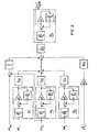
- FIG. 1 A block diagram to illustrate an estimation circuit including this filter is shown in the drawing, FIG. 1.
- the circuit exactly reproduces the recursion formula (5).
- the estimate at the exit X k k is amplified with ⁇ and led to an adder ⁇ 1 .
- From the at the input measured value u k + 1 of the delayed At measured value is fed via a delay circuit formed u k, which amplifies with r and also the adder ⁇ is supplied. 1
- the measured value Y k + 1 which is also present at the input, is fed to an adder ⁇ 2 .
- the result (corresponds to Y k + 1 - k + 1 ) is weighted in an amplifier with K k + 1 and fed to the adder ⁇ 3 , at its input also X k k + 1 is present.
- the estimate comes from ⁇ 3 X k + 1 k + 1 , which after the time At via a delay circuit in place of X k k occurs when in the next step X k + 2 k + 2 is estimated.
- the circuit continuously queries and processes the continuously measured variables u k + 1 and Y k + 1 (discretization), whereby the delay by At can also be achieved by storing the previous value.
- the individual sizes are vectors or matrices, so that a circuit with a breakdown according to individual components would contain the individual components several times, which was avoided here for a better overview and schematization, but is immediately apparent to the person skilled in the art.
- the unknown parameters can therefore be determined recursively using the least squares method.
- the structure of the second estimation circuit used is identical to that of the Kalman filter shown in the drawing.
- the position vector x is replaced by the parameter vector A formed from the elements of ⁇ and r.
- Claim 4 therefore provides for a correction circuit which uses this formula to be connected downstream of the Kalman filter. For example, in the event of a bubble passage, where the Kalman filter is briefly detuned, the value ⁇ determined according to formula (7) gives f, COR indicates the current value of the fuel temperature.
- the input variables u are noisy, but otherwise only change slowly, they can, as proposed in claim 5, be smoothed using low-pass filters.
- the time constants can be chosen to be large against the noise frequencies and still remain below the time that is significant for working point shifts.
- the time constants are on the order of a few seconds.
- the output of the correction circuit f, COR is somewhat noisy and can be smoothed according to claim 6.
- the time constant of the low-pass filter proposed for this purpose is very critical, since an excessively large time constant causes a phase error in f, causes COR so that this value does not follow changes quickly enough.
- An acceptable compromise between smoothing effect and phase error is a time constant of approximately 1 sec.
- the heat capacity of the fuel itself acts on changes in the fuel temperature like a low-pass filter with a certain time constant. Their size should be kept as an upper limit.
- the correction circuit can also be supplied with pure measured values at the input and does not require the output values of the Kalman filter. In this case, the correction circuit works even if the Kalman filter fails and contributes to the redundancy of the monitoring system. For this implementation, a low-pass filter would need to smooth the noisy inputs g angsgrösse 1/2 ( ⁇ T 0 + ⁇ T 1 ) can be provided.
- FIG. 1 Exemplary embodiments of the estimation and correction circuit are shown schematically in the drawing.
- Figure 1 already explained in connection with claim 3, shows the basic structure of a Kalman filter to solve the problem.
- the selected display type is based on drawings that are common in Kalman filter technology.
- Fig. 1 does not show a circuit diagram in the usual sense, but a kind of block diagram that can be implemented by an analog circuit or, for example, with a microprocessor.
- FIG. 2 shows a corresponding plan for an exemplary embodiment of the correction circuit.
- the circuit emulates formula (7) by means of adders and amplifiers.
- the input sizes are each smoothed by a low pass filter TP 1 , TP 2 , TP 3 .
- the time constants ⁇ 1 , ⁇ 2 , ⁇ 3 of the three filters are not very critical.
- amplifiers are identified by squares in which the gain factor is entered.
- Triangles with inscribed At mean retarders with a time difference of At between the input and output value.
- Adders are shown as circles, with the signs of the summands next to the inputs.
- the correction circuit shown shows an embodiment as occurs when the measured values are discretized, but this is not absolutely necessary.
- the continuously measured values at the input are adopted by the electronics at intervals At.
- the delayers save the value applied for the time At, so that the previous measured value is present at their output when the new one arrives at the input.
Landscapes
- Physics & Mathematics (AREA)
- Engineering & Computer Science (AREA)
- Plasma & Fusion (AREA)
- General Engineering & Computer Science (AREA)
- High Energy & Nuclear Physics (AREA)
- General Physics & Mathematics (AREA)
- Monitoring And Testing Of Nuclear Reactors (AREA)
Claims (8)


Applications Claiming Priority (4)
| Application Number | Priority Date | Filing Date | Title |
|---|---|---|---|
| DE3119045 | 1981-05-13 | ||
| DE3119045A DE3119045C2 (de) | 1981-05-13 | 1981-05-13 | Verfahren und Anordnung zur Feststellung und Meldung von Kühlungsstörungen in einem Brennelement eines Reaktorkerns |
| DE19813146374 DE3146374A1 (de) | 1981-11-23 | 1981-11-23 | Verfahren und anordnung zur feststellung und meldung von kuehlungsstoerungen in reaktorkernen |
| DE3146374 | 1981-11-23 |
Publications (3)
| Publication Number | Publication Date |
|---|---|
| EP0065155A2 EP0065155A2 (fr) | 1982-11-24 |
| EP0065155A3 EP0065155A3 (en) | 1983-01-12 |
| EP0065155B1 true EP0065155B1 (fr) | 1986-09-17 |
Family
ID=25793233
Family Applications (1)
| Application Number | Title | Priority Date | Filing Date |
|---|---|---|---|
| EP82103683A Expired EP0065155B1 (fr) | 1981-05-13 | 1982-04-29 | Procédé et dispositif pour la détermination et l'annonce de perturbations du système de refroidissement dans un faisceau d'éléments combustibles nucléaires d'un coeur de réacteur |
Country Status (2)
| Country | Link |
|---|---|
| EP (1) | EP0065155B1 (fr) |
| DE (1) | DE3273288D1 (fr) |
Families Citing this family (4)
| Publication number | Priority date | Publication date | Assignee | Title |
|---|---|---|---|---|
| DE3238522A1 (de) * | 1982-10-18 | 1984-04-19 | Interatom Internationale Atomreaktorbau Gmbh, 5060 Bergisch Gladbach | Verfahren und vorrichtung zur ueberwachung der reaktivitaetsbilanz des core eines kernreaktors und zur diagnose von reaktivitaetsstoerungen |
| FR2541481A1 (fr) * | 1983-02-23 | 1984-08-24 | Tomac Zeljko | Appareil a indiquer et a signaler l'etat d'installation et de fonctionnement d'objets tels que des machines, des vehicules, des caravanes ou similaires |
| FR2818427B1 (fr) * | 2000-12-15 | 2003-03-14 | Framatome Anp | Procede de determination du temps de doublement d'un flux neutronique dans le coeur d'un reacteur nucleaire |
| CN112114601B (zh) * | 2020-07-20 | 2021-04-13 | 南京弘图华智科技有限公司 | 一种自阻加热成形智能温度检测控制系统及其控制方法 |
Family Cites Families (6)
| Publication number | Priority date | Publication date | Assignee | Title |
|---|---|---|---|---|
| FR1509052A (fr) * | 1966-11-29 | 1968-01-12 | Automatisme Cie Gle | Dispositif de contrôle d'un réacteur nucléaire |
| DE1806182A1 (de) * | 1968-08-30 | 1970-03-05 | Atomic Energy Of Canada Ltd | Kernkraftwerksanlage |
| SE360496B (fr) * | 1972-02-18 | 1973-09-24 | Asea Ab | |
| CA1083268A (fr) * | 1977-07-27 | 1980-08-05 | Canadian General Electric Company Limited | Systemede mesure du courant, a correction dynamique |
| DE2814050A1 (de) * | 1978-03-31 | 1979-10-11 | Kraftwerk Union Ag | Verfahren zur sicherung der kuehlung eines kernreaktors und einrichtung dazu |
| DE3008198A1 (de) * | 1980-03-04 | 1981-09-10 | Kernforschungszentrum Karlsruhe Gmbh, 7500 Karlsruhe | Verfahren und schaltungsanordnung zum bestimmen des individuellen kuehlmitteldurchsatzes der brennelemente eines kernreaktors |
-
1982
- 1982-04-29 EP EP82103683A patent/EP0065155B1/fr not_active Expired
- 1982-04-29 DE DE8282103683T patent/DE3273288D1/de not_active Expired
Also Published As
| Publication number | Publication date |
|---|---|
| EP0065155A2 (fr) | 1982-11-24 |
| EP0065155A3 (en) | 1983-01-12 |
| DE3273288D1 (en) | 1986-10-23 |
Similar Documents
| Publication | Publication Date | Title |
|---|---|---|
| DE69723839T2 (de) | Überwachungssystem für industrielle anlage | |
| DE69324296T2 (de) | Verfahren zur Diagnose eines laufenden Prozesses | |
| EP2425308B1 (fr) | Dispositif et procédé pour analyser un résidu afin de détecter des erreurs de comportement dans un système d'avion | |
| EP3390967B1 (fr) | Procede de surveillance d'au moins deux capteurs redondants | |
| DE69729306T2 (de) | Ereignisfeststellung mit kurzen und langen Mittelwerten | |
| EP3454071B1 (fr) | Procédé de surveillance de la fonction d'un système de refroidissement d'un dispositif de résonance magnétique, dispositif de résonance magnétique, programme informatique et support de données lisible de manière électronique | |
| DE69511694T2 (de) | Identifizierung eines defekten neutronendetektors in einem kernreaktor | |
| DE3421522A1 (de) | Verfahren und einrichtung zur diagnose eines waermekraftwerks | |
| DE2714069A1 (de) | Verfahren und einrichtung zum feststellen und analysieren von fehlerquellen | |
| EP3210088B1 (fr) | Procédé et système d'assistance pour la détection d'une défaillance dans une installation | |
| DE68926429T2 (de) | Anlagen-Diagnoseapparat | |
| DE102018115155A1 (de) | Verfahren zum Vorhersagen von Anlagendaten und Vorrichtung, die es verwendet | |
| DE69014734T2 (de) | Verfahren für die Berechnung der Leistungsverteilung im Kern eines Kernkraftreaktors und Verfahren zum Kalibrieren der umgebenden Neutronendetektoren des Kerns eines Kernkraftreaktors. | |
| DE3117319C2 (fr) | ||
| EP0065155B1 (fr) | Procédé et dispositif pour la détermination et l'annonce de perturbations du système de refroidissement dans un faisceau d'éléments combustibles nucléaires d'un coeur de réacteur | |
| DE60130664T2 (de) | Stromkompensationsverfahren und einrichtung zum stromversorgungssystemschutz | |
| DE3119045C2 (de) | Verfahren und Anordnung zur Feststellung und Meldung von Kühlungsstörungen in einem Brennelement eines Reaktorkerns | |
| DE3146374A1 (de) | Verfahren und anordnung zur feststellung und meldung von kuehlungsstoerungen in reaktorkernen | |
| DE10114206A1 (de) | Überwachung und Steuerung von Prozessen unter Verwendung selbstüberprüfender Sensoren | |
| DE102021206751A1 (de) | Anomaliefaktorschätzverfahren, Anomaliefaktorschätzvorrichtung und Programm | |
| EP0108265B1 (fr) | Méthode et dispositif pour la surveillance du bilan neutronique du coeur d'un réacteur nucléaire et pour le diagnostic du changement de la réactivité | |
| WO2025026770A1 (fr) | Procédé de détection de décharges partielles dans un équipement électrique, et équipement | |
| CH643674A5 (de) | Sicherheits-einrichtung fuer einen kernreaktor. | |
| DE69025434T2 (de) | Komponentennetzwerk-Testanordnung, insbesondere für eine elektronische Schaltung | |
| CH623160A5 (en) | Method for determining the power distribution in a nuclear reactor, and nuclear reactor for carrying out the method |
Legal Events
| Date | Code | Title | Description |
|---|---|---|---|
| PUAI | Public reference made under article 153(3) epc to a published international application that has entered the european phase |
Free format text: ORIGINAL CODE: 0009012 |
|
| PUAL | Search report despatched |
Free format text: ORIGINAL CODE: 0009013 |
|
| AK | Designated contracting states |
Designated state(s): BE DE FR GB IT NL |
|
| AK | Designated contracting states |
Designated state(s): BE DE FR GB IT NL |
|
| 17P | Request for examination filed |
Effective date: 19830131 |
|
| RAP1 | Party data changed (applicant data changed or rights of an application transferred) |
Owner name: INTERATOM GESELLSCHAFT MIT BESCHRAENKTER HAFTUNG |
|
| GRAA | (expected) grant |
Free format text: ORIGINAL CODE: 0009210 |
|
| AK | Designated contracting states |
Kind code of ref document: B1 Designated state(s): BE DE FR GB IT NL |
|
| REF | Corresponds to: |
Ref document number: 3273288 Country of ref document: DE Date of ref document: 19861023 |
|
| ET | Fr: translation filed | ||
| ITF | It: translation for a ep patent filed | ||
| PLBE | No opposition filed within time limit |
Free format text: ORIGINAL CODE: 0009261 |
|
| STAA | Information on the status of an ep patent application or granted ep patent |
Free format text: STATUS: NO OPPOSITION FILED WITHIN TIME LIMIT |
|
| 26N | No opposition filed | ||
| ITTA | It: last paid annual fee | ||
| PGFP | Annual fee paid to national office [announced via postgrant information from national office to epo] |
Ref country code: GB Payment date: 19900331 Year of fee payment: 9 |
|
| PGFP | Annual fee paid to national office [announced via postgrant information from national office to epo] |
Ref country code: BE Payment date: 19900419 Year of fee payment: 9 |
|
| PGFP | Annual fee paid to national office [announced via postgrant information from national office to epo] |
Ref country code: FR Payment date: 19900427 Year of fee payment: 9 |
|
| PGFP | Annual fee paid to national office [announced via postgrant information from national office to epo] |
Ref country code: NL Payment date: 19900430 Year of fee payment: 9 |
|
| PGFP | Annual fee paid to national office [announced via postgrant information from national office to epo] |
Ref country code: DE Payment date: 19900625 Year of fee payment: 9 |
|
| PG25 | Lapsed in a contracting state [announced via postgrant information from national office to epo] |
Ref country code: GB Effective date: 19910429 |
|
| PG25 | Lapsed in a contracting state [announced via postgrant information from national office to epo] |
Ref country code: BE Effective date: 19910430 |
|
| BERE | Be: lapsed |
Owner name: INTERATOM G.M.B.H. Effective date: 19910430 |
|
| PG25 | Lapsed in a contracting state [announced via postgrant information from national office to epo] |
Ref country code: NL Effective date: 19911101 |
|
| NLV4 | Nl: lapsed or anulled due to non-payment of the annual fee | ||
| PG25 | Lapsed in a contracting state [announced via postgrant information from national office to epo] |
Ref country code: FR Effective date: 19911230 |
|
| GBPC | Gb: european patent ceased through non-payment of renewal fee | ||
| PG25 | Lapsed in a contracting state [announced via postgrant information from national office to epo] |
Ref country code: DE Effective date: 19920201 |
|
| REG | Reference to a national code |
Ref country code: FR Ref legal event code: ST |