EP0065178A1 - Mehrfache Verbindung für Unterseesystem - Google Patents
Mehrfache Verbindung für Unterseesystem Download PDFInfo
- Publication number
- EP0065178A1 EP0065178A1 EP82103808A EP82103808A EP0065178A1 EP 0065178 A1 EP0065178 A1 EP 0065178A1 EP 82103808 A EP82103808 A EP 82103808A EP 82103808 A EP82103808 A EP 82103808A EP 0065178 A1 EP0065178 A1 EP 0065178A1
- Authority
- EP
- European Patent Office
- Prior art keywords
- cables
- tubular part
- junction according
- armored
- cores
- Prior art date
- Legal status (The legal status is an assumption and is not a legal conclusion. Google has not performed a legal analysis and makes no representation as to the accuracy of the status listed.)
- Granted
Links
- 238000004873 anchoring Methods 0.000 claims abstract description 16
- 229910000831 Steel Inorganic materials 0.000 claims abstract description 12
- 239000010959 steel Substances 0.000 claims abstract description 12
- 238000010292 electrical insulation Methods 0.000 claims abstract description 3
- 238000009413 insulation Methods 0.000 claims description 4
- 239000013307 optical fiber Substances 0.000 claims description 2
- 239000004020 conductor Substances 0.000 description 2
- 238000000034 method Methods 0.000 description 2
- 239000004698 Polyethylene Substances 0.000 description 1
- 240000008042 Zea mays Species 0.000 description 1
- 239000000470 constituent Substances 0.000 description 1
- 239000011810 insulating material Substances 0.000 description 1
- 230000003287 optical effect Effects 0.000 description 1
- 229920001084 poly(chloroprene) Polymers 0.000 description 1
- -1 polyethylene Polymers 0.000 description 1
- 229920000573 polyethylene Polymers 0.000 description 1
- 230000001681 protective effect Effects 0.000 description 1
- 238000003466 welding Methods 0.000 description 1
Images
Classifications
-
- H—ELECTRICITY
- H02—GENERATION; CONVERSION OR DISTRIBUTION OF ELECTRIC POWER
- H02G—INSTALLATION OF ELECTRIC CABLES OR LINES, OR OF COMBINED OPTICAL AND ELECTRIC CABLES OR LINES
- H02G15/00—Cable fittings
- H02G15/08—Cable junctions
- H02G15/10—Cable junctions protected by boxes, e.g. by distribution, connection or junction boxes
- H02G15/12—Cable junctions protected by boxes, e.g. by distribution, connection or junction boxes for incorporating transformers, loading coils or amplifiers
- H02G15/14—Cable junctions protected by boxes, e.g. by distribution, connection or junction boxes for incorporating transformers, loading coils or amplifiers specially adapted for submarine cables
Definitions
- the present invention relates to a multiple junction ensuring the interconnection between cables serving several different directions, in their grouping zones, and more particularly between submarine coaxial cables or between submarine optical cables, at the level of the entry and output from an underwater telephone repeater or more generally from an intermediate or terminal device for underwater telephone links.
- the object of the present invention is to eliminate this difficulty by ensuring the assembly of independent cables to be connected to a repeater in a single section then allowing them to be connected in common through the only mechanical access to the repeater.
- said junction further comprises electrical insulation filling the free interior space of said tubular part and said anchoring part.
- Such a junction makes it possible to simultaneously connect several cables in particular to the input or the output of a repeater through a single corresponding mechanical access.
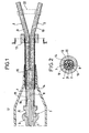
- Figure 1 is a front view of a junction according to the invention and the figure 2 is a sectional view of the junction of FIG. 1.
- FIG. 1 there is illustrated a junction made between two armored cables 1 and 2 for their simultaneous connection to an anchor piece 3.
- This anchor piece 3 has an axial passage 4. It is composed of a ball joint d anchor 6 and an element 5 having a knee-shaped spherical end which is articulated on the anchor ball 6.
- This anchor part 3 belongs in known manner to a set of mechanical and electrical connecting parts, providing a link of the articulated type or of the rigid type, between an electrical apparatus, such as a repeater, and / or its housing and a line cable of an underwater connection; it will therefore be understood that the type of connection illustrated here and its form have been given simply by way of example.
- the two cables 1 and 2 are armored cables, they serve different directions and are combined in their grouping zone.
- the cores of the two cables were identified in 7 and 8 and in their respective external armor, in steel wires, in 9 and 10.
- the free end of the tubular part 13 is fixed to the anchoring part 3.
- This part 13 has in this example a threaded end which is screwed onto the corresponding free threaded end of the element 5, the cores 7 and 8 then assembled passing through the anchoring part, these cores being able to be united in a single resulting internal conductor.
- the junction further comprises insulation 16 around the exposed cores 7 and 8 and then the resulting internal conductor, this insulation 16 is obtained by injecting an insulating material such as polyethylene into the free interior space of the tubular part 13 and of the anchoring part, made for example through holes not illustrated which the tubular part 13 presents.
- an insulating material such as polyethylene
- an external protective sleeve 17 for example made of neoprene, mounted around the anchoring part 3 and the tubular part. 13 partially covered by armor auxiliary 14. This sleeve 17 abuts on the flange 15 which holds it, it will be held at its other end on the casing of the electrical equipment not shown.
- FIG. 2 represents a section made at the level of the holding piece 12, that stuffing elements 20 and 21 are associated with the cables 1 and 2 in the holding piece 12 so that the whole retains a circular structure.
- the spacing of the armored cables 1 and 2, before their junction can be maintained by auxiliary pieces 22 for maintaining the spacing.
- the cores described can be made up of optical fiber cables, coaxial cables or cables with electric wires. It is also obvious that the junction can no longer concern two cables but three or even more which, in a grouping zone, are to be connected to the same electrical equipment, at the input or the output thereof, through a piece of equipment. anchoring secured to the casing of this apparatus.
Landscapes
- Engineering & Computer Science (AREA)
- Power Engineering (AREA)
- Cable Accessories (AREA)
- Multi-Conductor Connections (AREA)
- Coupling Device And Connection With Printed Circuit (AREA)
Applications Claiming Priority (2)
| Application Number | Priority Date | Filing Date | Title |
|---|---|---|---|
| FR8109070A FR2505569A1 (fr) | 1981-05-07 | 1981-05-07 | Jonction multiple pour systeme sous-marin |
| FR8109070 | 1981-05-07 |
Publications (2)
| Publication Number | Publication Date |
|---|---|
| EP0065178A1 true EP0065178A1 (de) | 1982-11-24 |
| EP0065178B1 EP0065178B1 (de) | 1985-01-30 |
Family
ID=9258165
Family Applications (1)
| Application Number | Title | Priority Date | Filing Date |
|---|---|---|---|
| EP82103808A Expired EP0065178B1 (de) | 1981-05-07 | 1982-05-04 | Mehrfache Verbindung für Unterseesystem |
Country Status (6)
| Country | Link |
|---|---|
| US (1) | US4447115A (de) |
| EP (1) | EP0065178B1 (de) |
| JP (1) | JPS57193919A (de) |
| DE (1) | DE3262112D1 (de) |
| FR (1) | FR2505569A1 (de) |
| NO (1) | NO155420C (de) |
Cited By (1)
| Publication number | Priority date | Publication date | Assignee | Title |
|---|---|---|---|---|
| WO1998044372A1 (en) * | 1997-04-03 | 1998-10-08 | Global Marine Systems Limited | Method and apparatus for joining underwater cable |
Families Citing this family (4)
| Publication number | Priority date | Publication date | Assignee | Title |
|---|---|---|---|---|
| FR2523731A1 (fr) * | 1982-03-17 | 1983-09-23 | Cables De Lyon Geoffroy Delore | Tete de cable pour cable immerge a fibre optiques |
| US4606603A (en) * | 1983-04-07 | 1986-08-19 | Lockheed Corporation | Underwater connector including integral bladder and seal with a set of constricting means |
| US4822956A (en) * | 1986-08-11 | 1989-04-18 | American Telephone And Telegraph Company | Coaxial cable |
| GB8824246D0 (en) * | 1988-10-17 | 1988-11-23 | British Telecomm | Bend restrictor for optical fibre cable |
Citations (5)
| Publication number | Priority date | Publication date | Assignee | Title |
|---|---|---|---|---|
| DE521552C (de) * | 1928-03-13 | 1931-03-24 | Aeg | Druckfeste Seekabel-Abzweigmuffe |
| US2155650A (en) * | 1937-11-10 | 1939-04-25 | Bell Telephone Labor Inc | Housing for repeater apparatus |
| FR2394875A1 (fr) * | 1977-06-16 | 1979-01-12 | Post Office | Perfectionnements aux cables sous-marins de telecommunication |
| US4189620A (en) * | 1978-04-10 | 1980-02-19 | Stange William F | Cable termination device |
| US4217464A (en) * | 1978-09-11 | 1980-08-12 | International Standard Electric Corporation | Cable anchor |
-
1981
- 1981-05-07 FR FR8109070A patent/FR2505569A1/fr active Granted
-
1982
- 1982-05-04 DE DE8282103808T patent/DE3262112D1/de not_active Expired
- 1982-05-04 EP EP82103808A patent/EP0065178B1/de not_active Expired
- 1982-05-05 NO NO821477A patent/NO155420C/no unknown
- 1982-05-06 JP JP57075924A patent/JPS57193919A/ja active Granted
- 1982-05-06 US US06/375,628 patent/US4447115A/en not_active Expired - Fee Related
Patent Citations (5)
| Publication number | Priority date | Publication date | Assignee | Title |
|---|---|---|---|---|
| DE521552C (de) * | 1928-03-13 | 1931-03-24 | Aeg | Druckfeste Seekabel-Abzweigmuffe |
| US2155650A (en) * | 1937-11-10 | 1939-04-25 | Bell Telephone Labor Inc | Housing for repeater apparatus |
| FR2394875A1 (fr) * | 1977-06-16 | 1979-01-12 | Post Office | Perfectionnements aux cables sous-marins de telecommunication |
| US4189620A (en) * | 1978-04-10 | 1980-02-19 | Stange William F | Cable termination device |
| US4217464A (en) * | 1978-09-11 | 1980-08-12 | International Standard Electric Corporation | Cable anchor |
Cited By (2)
| Publication number | Priority date | Publication date | Assignee | Title |
|---|---|---|---|---|
| WO1998044372A1 (en) * | 1997-04-03 | 1998-10-08 | Global Marine Systems Limited | Method and apparatus for joining underwater cable |
| US6353695B1 (en) | 1997-04-03 | 2002-03-05 | Global Marine Systems Limited | Method and apparatus for joining underwater cable |
Also Published As
| Publication number | Publication date |
|---|---|
| EP0065178B1 (de) | 1985-01-30 |
| FR2505569A1 (fr) | 1982-11-12 |
| FR2505569B1 (de) | 1984-05-25 |
| NO155420B (no) | 1986-12-15 |
| NO155420C (no) | 1987-03-25 |
| JPS57193919A (en) | 1982-11-29 |
| US4447115A (en) | 1984-05-08 |
| NO821477L (no) | 1982-11-08 |
| DE3262112D1 (en) | 1985-03-14 |
| JPH0145291B2 (de) | 1989-10-03 |
Similar Documents
| Publication | Publication Date | Title |
|---|---|---|
| EP0429036B1 (de) | Metallisches Gehäuse für elektrischen Verbinder | |
| EP0066829B1 (de) | Vorrichtung zur Verbindung der Enden zweier Untersee-Faseroptikkabel und Verfahren zur Montage der Vorrichtung | |
| EP0650219B1 (de) | Vorrichtung zur Sicherstellung der Kontinuität der elektrischen Abschirmung von Kabeln | |
| FR2568737A1 (fr) | Ligne sous-marine pour telecommunications a fibres optiques | |
| EP0065178B1 (de) | Mehrfache Verbindung für Unterseesystem | |
| CA2246651C (fr) | Dispositif de protection etanche pour une jonction de cables haute tension | |
| EP0347823B1 (de) | Vorrichtung zum Verbinden der Bewehrungen zweier drahtbewehrter Kabel, und Verfahren zum Herstellen dieser Vorrichtung | |
| EP0595708B1 (de) | Vorrichtung zum Verhindern des Schwindens der Isolation für kunststoffisolierte Energiekabel | |
| EP0129184B1 (de) | Mehrfachverbindung zwischen Unterseekabeln aus optischen Fasern | |
| EP0062345A1 (de) | Verfahren zur Verbindung fiberoptischer Unterseekabel | |
| EP0512486B1 (de) | Zugangskabel für einen Unterwasserverstärker | |
| FR2512218A1 (fr) | Connecteur de fibres optiques | |
| AU664285B2 (en) | Splicing box for submarine cable | |
| JPH07170645A (ja) | 複合ケーブルジョイント | |
| EP0508884B1 (de) | Verbinder für optische Faserkabel | |
| FR2772979A1 (fr) | Dispositif de raccordement electrique d'un bloc differentiel sur un disjoncteur ou analogue et bloc differentiel equipe d'un tel dispositif | |
| EP0513733B1 (de) | Erdseilverankerungseinrichtung | |
| EP1103094B1 (de) | Vorrichtung zum schutz einer unterbrechung der abschirmung eines mit in metallischen röhren verlegten lichtwelenleitern ausgestatteten elektrischen kabels | |
| EP0785608B1 (de) | Elektrische Kabelrinne mit einem flexiblen Element | |
| FR2463524A1 (fr) | Borne de derivation pour un cable d'alimentation en energie a quatre conducteurs | |
| FR3067864B1 (fr) | Element conducteur de mise a la terre | |
| FR2701123A1 (fr) | Jonction de câbles optiques sous-marins. | |
| FR2807572A1 (fr) | Connecteur electrique | |
| FR2494856A1 (fr) | Dispositif d'etancheite pour boitier de raccordement d'un cable sous enveloppe ondulee | |
| FR2699331A1 (fr) | Dispositif de blocage d'une connexion démontable de deux câbles de puissance. |
Legal Events
| Date | Code | Title | Description |
|---|---|---|---|
| PUAI | Public reference made under article 153(3) epc to a published international application that has entered the european phase |
Free format text: ORIGINAL CODE: 0009012 |
|
| AK | Designated contracting states |
Designated state(s): DE FR GB IT |
|
| 17P | Request for examination filed |
Effective date: 19830505 |
|
| ITF | It: translation for a ep patent filed | ||
| GRAA | (expected) grant |
Free format text: ORIGINAL CODE: 0009210 |
|
| AK | Designated contracting states |
Designated state(s): DE FR GB IT |
|
| REF | Corresponds to: |
Ref document number: 3262112 Country of ref document: DE Date of ref document: 19850314 |
|
| PLBE | No opposition filed within time limit |
Free format text: ORIGINAL CODE: 0009261 |
|
| STAA | Information on the status of an ep patent application or granted ep patent |
Free format text: STATUS: NO OPPOSITION FILED WITHIN TIME LIMIT |
|
| 26N | No opposition filed | ||
| ITTA | It: last paid annual fee | ||
| PGFP | Annual fee paid to national office [announced via postgrant information from national office to epo] |
Ref country code: GB Payment date: 19940422 Year of fee payment: 13 |
|
| PGFP | Annual fee paid to national office [announced via postgrant information from national office to epo] |
Ref country code: DE Payment date: 19940526 Year of fee payment: 13 |
|
| PGFP | Annual fee paid to national office [announced via postgrant information from national office to epo] |
Ref country code: FR Payment date: 19940530 Year of fee payment: 13 |
|
| PG25 | Lapsed in a contracting state [announced via postgrant information from national office to epo] |
Ref country code: GB Effective date: 19950504 |
|
| GBPC | Gb: european patent ceased through non-payment of renewal fee |
Effective date: 19950504 |
|
| PG25 | Lapsed in a contracting state [announced via postgrant information from national office to epo] |
Ref country code: DE Effective date: 19960201 |
|
| PG25 | Lapsed in a contracting state [announced via postgrant information from national office to epo] |
Ref country code: FR Effective date: 19960229 |
|
| REG | Reference to a national code |
Ref country code: FR Ref legal event code: ST |
|
| REG | Reference to a national code |
Ref country code: FR Ref legal event code: ST |