EP0065201B1 - Système pour déterminer la quantité de chaleur cédée par un radiateur - Google Patents
Système pour déterminer la quantité de chaleur cédée par un radiateur Download PDFInfo
- Publication number
- EP0065201B1 EP0065201B1 EP82103848A EP82103848A EP0065201B1 EP 0065201 B1 EP0065201 B1 EP 0065201B1 EP 82103848 A EP82103848 A EP 82103848A EP 82103848 A EP82103848 A EP 82103848A EP 0065201 B1 EP0065201 B1 EP 0065201B1
- Authority
- EP
- European Patent Office
- Prior art keywords
- temperature
- heating
- heating element
- heat
- measuring
- Prior art date
- Legal status (The legal status is an assumption and is not a legal conclusion. Google has not performed a legal analysis and makes no representation as to the accuracy of the status listed.)
- Expired
Links
Images


Classifications
-
- G—PHYSICS
- G01—MEASURING; TESTING
- G01K—MEASURING TEMPERATURE; MEASURING QUANTITY OF HEAT; THERMALLY-SENSITIVE ELEMENTS NOT OTHERWISE PROVIDED FOR
- G01K17/00—Measuring quantity of heat
- G01K17/06—Measuring quantity of heat conveyed by flowing media, e.g. in heating systems e.g. the quantity of heat in a transporting medium, delivered to or consumed in an expenditure device
- G01K17/08—Measuring quantity of heat conveyed by flowing media, e.g. in heating systems e.g. the quantity of heat in a transporting medium, delivered to or consumed in an expenditure device based upon measurement of temperature difference or of a temperature
Definitions
- the invention relates to a system for measuring the thermal energy output of space heaters according to the preamble of claim 1.
- So-called heat meters (US-A-3 301 049) have previously been used for the quantitative measurement and display of the heat energy output from a radiator to an enclosed space. With these heat meters, the product of the amount of water and the temperature difference between the radiator flow and return is measured. Such heat meters are technically complex, since expensive flow meters must be attached to each radiator in addition to temperature sensors.
- the object of the invention is to improve the known system for measuring the thermal energy output of space heaters in such a way that the thermal energy output of the associated radiator (s) is reliable under all possible conditions in practice, in particular even with low heating medium throughput quantities, i.e. strong throttle states and can be quantitatively more precisely.
- the system should be able to be adapted to any type of space radiator and even surface heating with little adjustment effort and should enable an exact and fair distribution of heating costs even with different space radiators or surface heating.
- the thermal performance test of space heaters according to DIN 4704 is carried out by measuring the flow and return temperatures and the heating medium flow in the space heater. This results in a characteristic curve U over AT, from which the radiator exponent n can be calculated.
- This exponent n differs from radiator type to radiator type and is between 1.1 and 1.5. The je-. The numerical value of n can be found in the test report of the radiator performance test.
- radiator exponent n is not only dependent on the radiator type, but can also change during operation depending on the heating medium flow or the throttle condition. This is taken into account in the invention.
- the values for the standard thermal output U N of the radiator recorded during the testing of space heaters according to DIN 4704 are pers and for the radiator exponent n also used to record the heat emission of these tested radiators during operation. These values are entered as parameters in the two planned input stages of the system.
- the computing device which preferably a microprocessor, for. B. contains the SAA 6000 manufactured by ITT
- the logarithmic mean temperature AT according to equation (3) is formed from the temperature values, exponentiated with the heating exponent n and integrated over time.
- the output signal of the microprocessor is a quantitative measure of the heat dissipation of the associated room heating, taking into account the heating medium throughput (throttle state) that changes during operation due to thermostatic valves.
- the output signal can be displayed to the user in a directly understandable manner via a display device downstream of the microprocessor, for example a digital display, in suitable thermal energy units such as kWh.
- a display device downstream of the microprocessor for example a digital display, in suitable thermal energy units such as kWh.
- the necessary temperature sensors can be produced and attached with comparatively very little effort; they can be connected to the microprocessor via an analog / digital converter.
- Both the A / D converter, the microprocessor and the digital displays can be implemented in integrated circuit technology and are therefore also inexpensive components.
- a particularly simple, empirical correction to take into account the changing heating medium throughput results from the following relationship:
- FIG. 8 shows a schematic illustration of a data transmission system for transmitting the measured values obtained on various devices via a power supply network to a central data acquisition device.
- FIG. 1 shows a device for measuring and displaying the heat emission from space heaters in association with a space heater 1.
- the space heater 1 is connected to the heating medium circuit via a flow line 2 and a return line 3.
- a thermostatic radiator valve 4 is installed in the flow line, through which the heating medium flow can be throttled to set a room air temperature.
- the device 6, which can be installed at any point in the room or outside the room, is coupled via lines 10 and 11 to a sensor 12 which scans the flow temperature T v and a sensor 13 which scans the return temperature T R.
- the sensors 12 and 13 can be arranged as simple contact sensors and contain known temperature-dependent semiconductor or resistance components.
- the sensor measuring the ambient air is integrated in the housing of the device 6.
- a digital display 24 is installed, which can be read from the outside and which provides a directly understandable display for the user of the heat energy given off by the radiator 1.
- the device 6 can be installed in a few minutes and ensures accurate energy consumption recording without intervention in the heating system.
- FIG. 2 shows a block diagram of the basic structure of the system for recording the energy consumption or the heat emission of the radiator 1.
- a microprocessor 15 which is provided by a power supply 16, for example a battery is fed and clocked by a clock 17.
- the standard heat output of the radiator 1 taken from the manufacturer table is entered via a first input stage.
- this can be set in 64 steps between the average values from 300 to 8360 (watts) in the illustrated embodiment.
- a special embodiment of the input stage 18 with 64 setting options is described below in connection with FIG. 3.
- the radiator exponent n is set in eight stages between 1.14 and 1.42 in accordance with the previous radiator test.
- the process variables namely the flow temperature T v , the return temperature T R and the room air temperature T i , which are measured by sensors 12, 13 and 20 in an analog manner, are input into the microprocessor via an analog / digital converter 21, so that they are from Microprocessor can be buffered and processed as temperature-proportional digital variables.
- the output signal of the microprocessor 15 is given via a collective output 22 to the display device 14, which displays the heat output in a numerical field 141 and from the microprocessor at a particularly high room air temperature T; > 22 ° C is particularly controlled so that a warning signal appears in a second field 142, for example in the form of a flashing display.
- N takes place by means of a dual circuit which is directly connected to the microprocessor 15 and in which the line paths of a binary circuit can be closed at six points with the aid of guide rubber plugs.
- the six line paths of the binary circuit correspond to six digits of the dual system, so that a total of 64 different settings can be made via the binary circuit.
- a corresponding arrangement is provided at input stage 19 for setting the radiator exponent n, in which three switches have to be operated selectively with the aid of conductive rubber plugs in order to set eight different values.
- These radiator constants must be entered during installation, and it must be ensured that the user cannot manipulate the presetting that is included in the measurement result.
- the guide rubber plugs are therefore not accessible from the outside but are arranged in a sealed housing of the device 6.
- FIG. 3 shows the circuit structure of a system according to the invention, in particular that of the A / D converter 21 and the input stages 18 and 19, while the microprocessor is shown as a block.
- the A / D converter 21 is only partially shown in FIG. 3; The components of the A / D converter shown interact with components of the microprocessor to convert the analog temperature measurement values into digital signals, the digital measurement signals in the exemplary embodiment described being developed in the microprocessor.
- the measurement signals arriving from the sensors 20, 13 and 12 are processed cyclically using a dual slope method.
- the field effect transistors F 1 ... F 5 are connected to earth.
- the gates of the field effect transistors F i ... F 5 are controlled separately by the microprocessor via separate control lines during the measurement cycle.
- An output signal U o representing the charge state of OP1 is generated at the output of OP1 and is applied to an input of an operational amplifier OP2 acting as a comparator.
- the operational amplifier OP2 develops a pulse signal at the output, the individual pulses of which are keyed when a certain threshold value of U o is reached and are switched off when the value falls below another threshold value of U o .
- the reloading of the integrator OP1 takes place with the aid of a further field effect transistor F 6 , which is connected via a series resistor R 6 and a field effect transistor F 7 to the positive connection of the power supply or battery 16 and is controlled by the microprocessor 15.
- the other resistors and capacitors shown at 21 in FIG. 3 have known functions and are not described in detail in order not to unnecessarily burden the invention.
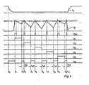
- a / D converter 21 The function of the A / D converter 21 is explained below with reference to FIG. 4, in which a family of curves is shown, which uses a measurement cycle to ... t 11 to determine the course of the signals or voltages at various nodes in the A / D converter represents.
- the measurement cycle begins at time t o , F 7 being controlled by microprocessor 15 and U, am Input from OP1 is reloaded.
- the gate of F 6 is also controlled by the microprocessor, ie U S6 is at an H level between t o and t 1 .
- U o at the output of OP1 rises to a predetermined threshold value at which the comparator formed by OP2 switches and develops an output signal U coM at an H level.
- the microprocessor 15 periodically samples the output of OP2 at the clock of the clock generator 17 and develops a first control pulse U S1 at the gate of F i as soon as (t 1 ) Uco M is switched to «1».
- the drive pulse U S1 makes F i conductive and the integrator OP1 is discharged via the measuring resistor 20 with a current which is dependent on the value of the measuring resistor 20, ie on the room or ambient temperature T i .
- the control pulse U S1 is keyed over a constant time.
- OP1 is reloaded by actuating F 6 with an actuating pulse U S6 until the upper threshold value of U o is reached (t 3 ).
- another pulse U coM is developed at the output of OP2 and input into the microprocessor 15.
- the charging time of OP1 between the times t 2 and t 3 is proportional to the extent of the discharge when the control pulse U S1 is present , that is to say proportional to the increase in U o in the discharge interval t 2 -t 1 .
- the charging interval t 3 -t 2 is therefore a measure of the value of the measuring resistor 20 and, in the case of linear measurement behavior, a measure of the room air temperature T i .
- the interval t 3 -t 2 is therefore the first measurement interval t m1 .
- the measuring resistors 13 (T R ) and 12 (T v ) as well as the reference resistors R 4 and R 5 are queried and then the measuring intervals tm 2 , tm 3 , tm 4 and t m5 are scanned until the end of the measuring cycle at time t 11 .
- the field effect transistors F 2 to F 5 are driven in succession with constant control pulses U S2 to U s5 .
- the measuring pulses t m1 ... t m5 are pulse duration modulated pulses, the pulse duration of which is exactly proportional to the resistor 20, 13, 12, R 4 and R 5 discharging the integrator OP1.
- the resistors R 4 and R 5 are reference resistors which correspond to a predetermined reference temperature of, for example, 60 ° and 0 ° C. As a result, the system can calibrate itself and measurement errors due to manufacturing tolerances of the components used and temperature drifts are avoided or at least largely compensated for.
- the pulse duration U S6 in the measuring intervals t m1 ... t m5 is temporarily stored in the microprocessor with the aid of a suitable register and, after suitable implementation in accordance with equation (5) and integration over time, is applied as an output signal to the lines 22 or the display device 14.
- the temperature difference T v -T R (measuring intervals t m3 - tm2) also represents a usable measure for the throttle condition of the radiator 1 or for the amount of heating medium that is used in the correction device 151 in the microprocessor 15 according to equation (5) for the empirical correction of the strong throttling changing radiator exponent n is used.
- the input devices 18 and 19 for entering the radiator constants taken from the manufacturer table on the basis of the test Q N and n are each designed as a diode matrix;
- the line paths to the individual diodes can, as mentioned above, be closed with the aid of a conductive rubber plug in accordance with a conventional binary code.
- the line path 42 can also be closed with the aid of a rubber stopper.
- a / D converter 21 and the input stages 18 and 19 described is only one exemplary embodiment; It is clear to the person skilled in the art that other versions of A / D converters and other forms of converting the analog incoming process variables T i , T R and T v into digital quantities that can be processed by the microprocessor 15 are possible as well as a different way of entering the radiator characteristics Q N and n, e.g. B. by coding switches or cable bridges.
- the sensor 20 for measuring the radiator ambient temperature or the room air temperature T i and the input means for the input stages 18 and 19 should be accommodated in a tamper-proof manner, for example in the housing of the device 6.
- the querying of the temperature measured values can take place in measuring cycles which have longer distances from one another, since in practice rapid temperature jumps in the measured temperatures are not to be expected.
- the system described therefore has a very low electrical power consumption, so that a battery has a service life of, for example, 2 heating periods (2 years).
- a so-called one-pipe heater is shown schematically, in which, to avoid incorrect measurements, the flow and return temperature sensors 12 and 13 are not directly on the flow and return flows 2 and 3, but on for the flow and return temperatures T v and T R representative locations of the surface of the radiator 1 itself are mounted.
- the forward and return flows 2 and 3 open into a valve 31 provided with a valve and are coaxially introduced into or removed from the radiator 1.
- a bypass 32 is provided between the flow 2 and the return 3, via which a partial flow of the flow is passed directly into the return pipe 3.
- the inflow of heating medium from the flow 2 into the radiator 1 takes place through an annular space which surrounds the return pipe projecting lance-shaped into the interior of the radiator.
- the temperature sensors 12 and 13 are mounted at those points on the radiator surface which are representative of the flow and return temperatures similar to the measurements on the flow and return in the exemplary embodiment according to FIG. 1.
- the flow temperature sensor 12, which is also shown here as a surface sensor, could also be attached to the flow connection 2 in the exemplary embodiment according to FIG. 5, since the flow temperature is not influenced by the bypass flow.
- FIG. 6 shows a schematic system diagram of the recording of the heat consumption in the case of surface or floor heating systems with two heated rooms I and II.
- both rooms are supplied with heating medium by a heating distributor 200.
- Room I is a smaller room in the illustrated embodiment with a heating register or line 1a and Room II with two heating registers. -strands 1b and 1c provided.
- the flow and return temperature sensors 12a, b, c and 13a, b, c are each attached to the flow and return connections of the rooms or the heating elements. This attachment has the advantage that the heat transfer paths between the heat distributor 200 and the rooms are also included in the measurement. In an alternative arrangement, however, the flow and return temperature sensors can also be attached to the flow and return 2 or 3 of the individual heating registers immediately after they enter the room.
- the room sensors 20a and 20bc assigned to the two heat emission detection devices 6a and 6bc are arranged at a suitable location in the associated room I and 11, respectively.
- the room temperature sensor is housed in a suitable housing or jacket to prevent unauthorized access and, for example, attached to a room wall - if necessary in connection with a socket.
- each heat detection device 6a or 6bc can correspond to that of the heat meter 6 described with reference to FIGS. 2 and 3.
- the heating constants U N and n can be determined according to (in preparation) DIN regulations for underfloor heating and entered into the memory of the computing device 15.
- the values for U N and n can also be taken from the design data for underfloor heating determined by the manufacturer (calculation of the standard heat requirement as standard heat output based on m 2 and room covering, taking into account the heating medium excess temperature (based on the supply and return temperatures).
- the U N and n values can also be determined via the pipe length, the pipe cross-section and the pipe heat resistance or via the pipe material, the heat transfer distances outside the monitored and recorded rooms being taken into account by suitable supplements.
- C values thermal contact factors
- the C value for metal is 1.0 and that for plastic is 1.1.
- the number of possible input values for Q N depends on the possibility of variation of the associated input device 18 (FIG. 3). It is usually sufficient to enter 128 U N values.
- the n-value is usually programmed as a fixed value for underfloor heating and can be between 0.0 and 1.42 in steps of 0.06.
- the inputs of the U N and n values also depend on the measurement method used and the assignment of the individual detection devices 6a and 6bc to the rooms and / or heating elements.
- the device 6a measures the heat consumption of a heating register or heating element 1a.
- the function and input of the heating constants U N and n correspond to those in the exemplary embodiment described with reference to FIGS. 1 to 3 for the determination of the heat dissipation of room radiators.
- the device 6bc monitors several (two) heating lines 1b and 1c in a room 11. If the values for the heating lines 1b and 1c are identical, the Q N and n values can be entered once and together.
- the U N and n values must be entered one after the other using appropriate input devices. Basically the same applies in the event that a heat recording device 6 with a correspondingly large number of measuring points is assigned to a larger number of heating registers or even different rooms in an apartment.
- the flow and return temperature sensors 12, 13 assigned to a heat detection device 6 are queried one after the other during operation by an interrogation logic.
- the heat consumption values determined in a query cycle for the various heating lines can be combined in the device 6 and displayed. This makes it easier to record heat consumption for the entire apartment or for a customer.
- the temperature measurement values derived from the flow and return flows are also recognized as such in the computing device and are defined as the flow temperature or return temperature. It must therefore be avoided that the measurement result is falsified or impaired if the temperature sensors are mixed up.
- One possibility of reliably evaluating the temperature tapped at the flow as the flow temperature T v and the temperature tapped at the return as the return temperature T R is shown in FIG. 7.
- the measured value proportional signals of the two temperature sensors attached to the forward and return lines are each applied to one of the AC connections of a Wheatstone bridge 50.
- the higher signal f (T v ) corresponding to the flow temperature measured value T v basically appears at the positive “DC output”, while the signal f (T R ) corresponding to the return temperature measured value appears at the negative “DC connection” of the bridge 50.
- the temperature differences required for the thermal energy detection in the computing device 15 for determining the logarithmic excess temperature AT (equation 3) can be obtained via suitable differential amplifiers.
- a corresponding digital logic circuit can also be provided at the input of the microprocessor 15, or the microprocessor can be programmed in such a way that the highest temperature measurement value is evaluated as the flow temperature measurement value .
- the system described provides a quantitative, for example digital, consumption display of the amount of heat emitted via the connected heater 1.
- the consumer has an immediately understandable and ongoing control of his thermal energy consumption.
- the possibility of quantitative heat consumption recording offered by this system is particularly important when many consumers, for example in high-rise buildings or multi-party houses, are connected to a common heat source and a fair distribution of heating costs has to be carried out.
- the system does not require a connection to a power source, but can be powered from its own power supply unit or battery, which can be recharged via the power supply.
- each measuring device 6 to which the process variables T i , T v and T R are fed, has a frequency generator FG, which generates a carrier frequency specific to the device (6a).
- the heat energy output Q of the heating measured by the processor 15 is converted in a converter DFC into a frequency proportional to the measured value, with which the carrier frequency of the frequency generator FG is modulated.
- the modulated signal is transmitted to the house mains via a coupler and a socket.
- the coupler galvanically separates the FG from the conductive phase of the power network.
- the battery 16 assigned to the processor 15 or the device 6 serves as the operating current source for the transmitter.
- All phase conductors R, S and T of the power network are coupled via the transformer arrangement 52 shown schematically in FIG. 1 so that the modulated frequency entered via the phase conductor R can be tapped on the receiver side, for example on the phase conductor T, as shown in FIG.
- the various measured value transmitters 6a, 6b and 6c coupled via the network to the control center 60 each have carrier frequencies located in different channels, so that the transmit signals originating from different transmitters can be separated and individually evaluated on the receiver side according to the different carrier frequencies. This takes place in a crossover FW in the control center 60.
- the crossover FW is followed by a converter arrangement FDC in which the frequency-modulated signals which are separated from one another and are proportional to the measured value are converted into digital signals (or analog voltages). The latter can be recorded, displayed or further processed in the control center.
- line paths in the form of direct ring lines can also be provided.
- the measured value transmission can also take place via secondary waveguides, such as water pipes, heating pipes or other lines suitable for transmitting electromagnetic waves, which can be interrupted at intervals without significant loss of energy.
- the system described with reference to FIG. 8 for the data transmission between the measuring device 6 and the control center 60 can also be provided for the transmission of measured values between the room sensor 20 and the device 6; this applies in particular to surface heating systems in which room sensors are generally arranged away from the device 6.
- the central units 60 can be used as both central apartment units and central building units to be seen. If the central unit 60 as well as the connected transmitters 6 are each assigned transceivers, input and call functions can also be performed from the central unit.
- the switch-off condition is therefore only fulfilled if the values fall below or reach the two limit values.
Landscapes
- Chemical & Material Sciences (AREA)
- Engineering & Computer Science (AREA)
- Combustion & Propulsion (AREA)
- Physics & Mathematics (AREA)
- General Physics & Mathematics (AREA)
- Measuring Temperature Or Quantity Of Heat (AREA)
- Protection Of Generators And Motors (AREA)
- Heat-Pump Type And Storage Water Heaters (AREA)
- Steam Or Hot-Water Central Heating Systems (AREA)
- Air Conditioning Control Device (AREA)
- Investigating Or Analyzing Materials Using Thermal Means (AREA)
Claims (20)


Priority Applications (1)
| Application Number | Priority Date | Filing Date | Title |
|---|---|---|---|
| AT82103848T ATE29172T1 (de) | 1981-05-06 | 1982-05-05 | System zur messung der waermeenergieabgabe von raumheizungen. |
Applications Claiming Priority (2)
| Application Number | Priority Date | Filing Date | Title |
|---|---|---|---|
| US260966 | 1981-05-06 | ||
| US06/260,966 US4455095A (en) | 1980-05-08 | 1981-05-06 | System for measuring the heat energy emission of room heating elements |
Publications (3)
| Publication Number | Publication Date |
|---|---|
| EP0065201A2 EP0065201A2 (fr) | 1982-11-24 |
| EP0065201A3 EP0065201A3 (en) | 1984-02-22 |
| EP0065201B1 true EP0065201B1 (fr) | 1987-08-26 |
Family
ID=22991406
Family Applications (1)
| Application Number | Title | Priority Date | Filing Date |
|---|---|---|---|
| EP82103848A Expired EP0065201B1 (fr) | 1981-05-06 | 1982-05-05 | Système pour déterminer la quantité de chaleur cédée par un radiateur |
Country Status (4)
| Country | Link |
|---|---|
| US (1) | US4455095A (fr) |
| EP (1) | EP0065201B1 (fr) |
| AT (1) | ATE29172T1 (fr) |
| DE (1) | DE3277078D1 (fr) |
Cited By (4)
| Publication number | Priority date | Publication date | Assignee | Title |
|---|---|---|---|---|
| DE29801695U1 (de) * | 1998-02-02 | 1998-05-20 | Klamert, Dieter, 87700 Memmingen | Heizkörper-Thermostatventil mit Durchflußanzeige |
| DE10108852C1 (de) * | 2001-02-23 | 2002-08-29 | Techem Service Ag | Raumtemperaturregelung |
| DE102005034226A1 (de) * | 2005-07-19 | 2007-02-22 | Kundo System Technik Gmbh | Verfahren zum Erfassen von raumspezifischen Umweltdaten in Räumen |
| EP2327971A3 (fr) * | 2009-11-25 | 2014-04-30 | Metrona Wärmemesser Union Gmbh | Procédé d'analyse de la répartition des quantités de chaleur dans un système de chauffage et dispositif d'exécution du procédé |
Families Citing this family (40)
| Publication number | Priority date | Publication date | Assignee | Title |
|---|---|---|---|---|
| DE3212611A1 (de) * | 1982-04-05 | 1983-10-06 | Bosch Gmbh Robert | Verfahren zur temperaturkompensation eines sensorsignales |
| US4591988A (en) * | 1983-07-13 | 1986-05-27 | Control Energy Corporation | Energy cost allocation method and system |
| US4545210A (en) * | 1984-04-06 | 1985-10-08 | Carrier Corporation | Electronic program control for a refrigeration unit |
| US4773766A (en) * | 1984-09-04 | 1988-09-27 | Daido Tokushuko Kabushiki Kaisha | Method of measuring temperatures and portable recorder for storing temperature data |
| US4577977A (en) * | 1985-04-01 | 1986-03-25 | Honeywell Inc. | Energy submetering system |
| US4718776A (en) * | 1985-08-12 | 1988-01-12 | Ball Corporation | Portable monitoring device and method |
| US4819441A (en) * | 1987-02-27 | 1989-04-11 | Thermo King Corporation | Temperature controller for a transport refrigeration system |
| US4833688A (en) * | 1988-01-07 | 1989-05-23 | Combustion Engineering, Inc. | Two-phase flow quality measuring device |
| US4928751A (en) * | 1988-05-25 | 1990-05-29 | The Eldon Corporation | Computer controlled waste heat reclaimer |
| US4959804A (en) * | 1988-07-12 | 1990-09-25 | Baxter International Inc. | Parameter measuring apparatus |
| US4903498A (en) * | 1988-08-26 | 1990-02-27 | Thermo King Corporation | Temperature controlling for a transport refrigeration system |
| US4909067A (en) * | 1988-10-28 | 1990-03-20 | Combustion Engineering, Inc. | Steam quality measurement using separating calorimeter |
| US5031125A (en) * | 1989-04-06 | 1991-07-09 | Rikagaku Kenkyusho | Apparatus for measuring electron temperature |
| US5026171A (en) * | 1989-06-07 | 1991-06-25 | Feller Murray F | Apparatus for flow rate and energy transfer measurements |
| US5156459A (en) * | 1989-09-01 | 1992-10-20 | The United States Of America As Represented By The United States Department Of Energy | Radiation beam calorimetric power measurement system |
| US5178206A (en) * | 1990-05-25 | 1993-01-12 | American Stabilis, Inc. | Thermal storage control logic for storage heaters |
| DE69232673T2 (de) * | 1991-04-23 | 2003-03-13 | Kabushiki Kaisha Toshiba, Kawasaki | Tiefsttemperaturmessausrüstung |
| US5515297A (en) * | 1993-10-14 | 1996-05-07 | Bunting; John E. | Oil burner monitor and diagnostic apparatus |
| US5539672A (en) * | 1993-12-13 | 1996-07-23 | Hobart Corporation | Microprocessor-based temperature control circuit |
| US5775809A (en) * | 1996-07-11 | 1998-07-07 | Measurement Dynamics Llc | Vehicle compartment temperature recorder |
| DE19703359A1 (de) * | 1997-01-30 | 1998-08-06 | Telefunken Microelectron | Verfahren zur Temperaturkompensation bei Meßsystemen |
| DE19724748A1 (de) * | 1997-06-12 | 1998-12-17 | Raab Karcher Energy Services G | Verfahren zur Erfassung und Auswertung von temperaturabhängigen Verbrauchswerten |
| US6960017B1 (en) * | 2002-01-24 | 2005-11-01 | Sandia Corporation | Non-invasive energy meter for fixed and variable flow systems |
| RU2247340C2 (ru) * | 2003-01-29 | 2005-02-27 | Общество с ограниченной ответственностью Научно- производственная компания "Современные строительные технологии" | Многофункциональный тепловой счетчик |
| DE10306465A1 (de) * | 2003-02-14 | 2004-09-02 | Siemens Building Technologies Ag | Verfahren zur Bestimmung des Zählfortschrittes in einem elektronischen Heizkostenverteiler, so dass die Möglichkeit des gemischten Einbaus von Heizkostenverteilern unterschiedlicher Bauart in einer Abrechnungseinheit (Mischverbau) besteht |
| CN100371693C (zh) * | 2003-10-22 | 2008-02-27 | 赵富 | 一种集中采暖分室计量方法及专用计量装置 |
| US8095243B2 (en) * | 2005-07-11 | 2012-01-10 | Minesh Bhakta | Power monitoring and control system and method |
| US7555365B2 (en) * | 2005-07-11 | 2009-06-30 | Minesh Bhakta | Power monitoring and control system and method |
| DK177137B1 (da) | 2005-09-02 | 2012-01-30 | Brunata Internat A S | Fremgangsmåde, varmemåler og anlæg til fordeling af varmeudgifter |
| DE102005045198C5 (de) * | 2005-09-21 | 2009-06-25 | Techem Energy Services Gmbh | Verfahren und Vorrichtung zur Bestimmung von Wärmekenndaten eines Heizkörpers |
| CN100460818C (zh) * | 2006-06-23 | 2009-02-11 | 辽宁环佳高科节能技术工程有限公司 | 分户供暖温控计费装置及热费计算方法 |
| IT1398706B1 (it) * | 2009-06-17 | 2013-03-08 | Bonetti | Dispositivo di contabilizzazione dell'energia termica emessa da termosifoni, termoconvettori o simili, particolarmente per la ripartizione dei costi di riscaldamento |
| DE102010047913A1 (de) * | 2010-10-11 | 2012-04-12 | Kübrich Ingenieurgesellschaft mbH | Intelligenter Heizkreisverteiler und Verfahren zum Betrieb desselben |
| DE102012104268A1 (de) * | 2012-05-16 | 2013-11-21 | Wzg-Technik Gmbh | Verfahren und Vorrichtung zur Bestimmung der Wärmeabgabe |
| DE102017105740B4 (de) * | 2017-03-17 | 2018-10-11 | Techem Energy Services Gmbh | Verfahren und Vorrichtung zur Erfassung der Wärmeabgabe eines Heizkörpers |
| DE102018002667A1 (de) * | 2018-03-31 | 2019-10-02 | Thomas Krämer | Verfahren zur verursacherbezogenen Feststellung von Umweltbelastungen durch Öl- und Gasheizanlagen zur Erhebung einer verursacherkonformen Umweltsteuer |
| ES2932266T3 (es) * | 2018-11-21 | 2023-01-17 | Csem Centre Suisse Delectronique Et De Microtechnique Sa | Procedimiento de medición de la salida de potencia de intercambiadores de calor |
| DE102021203001B4 (de) | 2021-03-26 | 2023-01-19 | Qundis Gmbh | Verfahren zum Betrieb einer Heizkostenverteilervorrichtung und Heizkostenverteilervorrichtung |
| DE102021203000B4 (de) | 2021-03-26 | 2023-01-19 | Qundis Gmbh | Verfahren zum Betrieb einer Heizkostenverteilervorrichtung und Heizkostenverteilervorrichtung |
| AT526287A1 (de) * | 2022-06-27 | 2024-01-15 | Purmo Group Plc | Energiemessung von Heizkörpern |
Citations (1)
| Publication number | Priority date | Publication date | Assignee | Title |
|---|---|---|---|---|
| DE2847217A1 (de) * | 1978-10-30 | 1980-05-08 | Bleiker Werner | Anordnung zur messung der waermeenergieabgabe von raumheizkoerpern |
Family Cites Families (8)
| Publication number | Priority date | Publication date | Assignee | Title |
|---|---|---|---|---|
| SE7409403L (sv) * | 1974-07-18 | 1976-01-19 | Svensk Vaermemaetning | Forfarande for uppmetning av vermeforbrukningen i enskilda legenheter i flerfamiljshus samt anordning for utforande av forfarandet |
| YU39528B (en) * | 1974-10-21 | 1984-12-31 | M Silvin Leskovar | Measuring-transmitting device high-tension lines |
| DE2521812A1 (de) * | 1975-05-16 | 1976-11-25 | Jaeger Gmbh G & J | Kontrollanlage fuer temperaturueberwachungsgeraete |
| FI65331C (fi) * | 1977-09-01 | 1984-04-10 | Insele Oy | Reglerings- och maetningssystem foer uppvaermning/avkylning lagenhetsvis samt foerfarande foer kalibrering av systemet |
| DE2842899A1 (de) * | 1977-11-24 | 1979-05-31 | Sulzer Ag | Dampfkreislauf |
| DE2912522C2 (de) * | 1979-03-29 | 1982-09-02 | Johannes Schultz | Heizkostenverteiler zur Montage auf der Oberfläche jedes Heizkörpers einer Heizanlage |
| CH644460A5 (de) * | 1980-02-27 | 1984-07-31 | Aquametro Ag | Anlage zum transport von waerme mittels eines fluides. |
| DK149010C (da) * | 1980-10-16 | 1986-05-26 | Iss Clorius Int As | Anlaeg til saerskilt registrering af varmeforbruget for et antal varemafgivende elementer, saasom radiatorer |
-
1981
- 1981-05-06 US US06/260,966 patent/US4455095A/en not_active Expired - Lifetime
-
1982
- 1982-05-05 AT AT82103848T patent/ATE29172T1/de not_active IP Right Cessation
- 1982-05-05 DE DE8282103848T patent/DE3277078D1/de not_active Expired
- 1982-05-05 EP EP82103848A patent/EP0065201B1/fr not_active Expired
Patent Citations (1)
| Publication number | Priority date | Publication date | Assignee | Title |
|---|---|---|---|---|
| DE2847217A1 (de) * | 1978-10-30 | 1980-05-08 | Bleiker Werner | Anordnung zur messung der waermeenergieabgabe von raumheizkoerpern |
Cited By (4)
| Publication number | Priority date | Publication date | Assignee | Title |
|---|---|---|---|---|
| DE29801695U1 (de) * | 1998-02-02 | 1998-05-20 | Klamert, Dieter, 87700 Memmingen | Heizkörper-Thermostatventil mit Durchflußanzeige |
| DE10108852C1 (de) * | 2001-02-23 | 2002-08-29 | Techem Service Ag | Raumtemperaturregelung |
| DE102005034226A1 (de) * | 2005-07-19 | 2007-02-22 | Kundo System Technik Gmbh | Verfahren zum Erfassen von raumspezifischen Umweltdaten in Räumen |
| EP2327971A3 (fr) * | 2009-11-25 | 2014-04-30 | Metrona Wärmemesser Union Gmbh | Procédé d'analyse de la répartition des quantités de chaleur dans un système de chauffage et dispositif d'exécution du procédé |
Also Published As
| Publication number | Publication date |
|---|---|
| EP0065201A3 (en) | 1984-02-22 |
| US4455095A (en) | 1984-06-19 |
| DE3277078D1 (en) | 1987-10-01 |
| ATE29172T1 (de) | 1987-09-15 |
| EP0065201A2 (fr) | 1982-11-24 |
Similar Documents
| Publication | Publication Date | Title |
|---|---|---|
| EP0065201B1 (fr) | Système pour déterminer la quantité de chaleur cédée par un radiateur | |
| DE69309100T2 (de) | Verfahren und Vorrichtung zur Messung eines Flüssigkeitsstromes | |
| US4049044A (en) | Heating and cooling system consumption meter | |
| EP0035085B1 (fr) | Installation pour le transport de chaleur au moyen d'un fluide | |
| EP1770469B1 (fr) | Procédeé et appareil pour déterminer les données thermiques caractéristiques d'un radiateur | |
| DE3235257A1 (de) | Verfahren und vorrichtung zur direkten messung der von einem stroemungsmittel uebertragenen waermemenge | |
| EP0015407B1 (fr) | Dispositif de détermination électrique de la consommation de chaleur de radiateurs individuels | |
| US4459041A (en) | Method and apparatus for the indirect measuring of thermal energy | |
| DE3130591C2 (fr) | ||
| DE2734406A1 (de) | Verfahren zur elektrischen erfassung der von in raeumen angeordneten radiator- heizkoerpern abgegebenen waermeenergien | |
| DE3530946C3 (de) | Gerät zum Messen von einem Warmwassernetz entzogenen Warmwassermengen | |
| DE3435224A1 (de) | Elektronisches heizungsmessverfahren | |
| DE3330941C2 (de) | Schaltungsanordnung zum Erfassen und Anzeigen der von den Heizkörpern einer vorgegebenen Anzahl von Wohnungen eines Hauses oder Wohnblocks abgegebenen anteiligen Wärmemengen | |
| DE4312837C1 (de) | Vorrichtung zur Strömungsmessung in Druckluftanlagen und Strömungsmeßeinrichtung hierfür | |
| CH607001A5 (en) | Mass transfer measuring appts. for heat fluid flow | |
| DE3130538C2 (de) | Elektronischer Heizkostenverteiler für eine Anzahl von Wohnungen | |
| DE19716863A1 (de) | Fußbodenheizung mit einer Temperaturregeleinrichtung | |
| DE19738797A1 (de) | Verfahren und Anordnung zur Erfassung und Übermittlung von Daten von Wohneinrichtungen | |
| DE2925116A1 (de) | Schaltungsanordnung zur erfassung der von den heizkoerpern einer wohnung abgegebenen waermemenge | |
| DE3426885C2 (fr) | ||
| DE3343997C1 (de) | Schutzschaltung für Temperatur-Sensoren | |
| DE2847217A1 (de) | Anordnung zur messung der waermeenergieabgabe von raumheizkoerpern | |
| DE4421969A1 (de) | Verfahren und Anordnung zur Ermittlung der von einem Strömungsmittel an einzelne, von einer gemeinsamen Wärmeträgereinspeisung betriebenen, Wärmeverbraucher übertragenen Wärmemenge | |
| CH442793A (de) | Einrichtung zum Messen der Wärmeleitfähigkeit und des Wärmeflusses | |
| DE102021203001B4 (de) | Verfahren zum Betrieb einer Heizkostenverteilervorrichtung und Heizkostenverteilervorrichtung |
Legal Events
| Date | Code | Title | Description |
|---|---|---|---|
| PUAI | Public reference made under article 153(3) epc to a published international application that has entered the european phase |
Free format text: ORIGINAL CODE: 0009012 |
|
| AK | Designated contracting states |
Designated state(s): AT BE CH DE FR GB IT LU NL SE |
|
| 17P | Request for examination filed |
Effective date: 19830525 |
|
| PUAL | Search report despatched |
Free format text: ORIGINAL CODE: 0009013 |
|
| AK | Designated contracting states |
Designated state(s): AT BE CH DE FR GB IT LI LU NL SE |
|
| GRAA | (expected) grant |
Free format text: ORIGINAL CODE: 0009210 |
|
| AK | Designated contracting states |
Kind code of ref document: B1 Designated state(s): AT BE CH DE FR GB IT LI LU NL SE |
|
| PG25 | Lapsed in a contracting state [announced via postgrant information from national office to epo] |
Ref country code: IT Free format text: LAPSE BECAUSE OF FAILURE TO SUBMIT A TRANSLATION OF THE DESCRIPTION OR TO PAY THE FEE WITHIN THE PRESCRIBED TIME-LIMIT;WARNING: LAPSES OF ITALIAN PATENTS WITH EFFECTIVE DATE BEFORE 2007 MAY HAVE OCCURRED AT ANY TIME BEFORE 2007. THE CORRECT EFFECTIVE DATE MAY BE DIFFERENT FROM THE ONE RECORDED. Effective date: 19870826 Ref country code: BE Effective date: 19870826 |
|
| REF | Corresponds to: |
Ref document number: 29172 Country of ref document: AT Date of ref document: 19870915 Kind code of ref document: T |
|
| PG25 | Lapsed in a contracting state [announced via postgrant information from national office to epo] |
Ref country code: SE Effective date: 19870831 |
|
| REF | Corresponds to: |
Ref document number: 3277078 Country of ref document: DE Date of ref document: 19871001 |
|
| ET | Fr: translation filed | ||
| PG25 | Lapsed in a contracting state [announced via postgrant information from national office to epo] |
Ref country code: GB Effective date: 19880505 |
|
| PG25 | Lapsed in a contracting state [announced via postgrant information from national office to epo] |
Ref country code: LU Free format text: LAPSE BECAUSE OF NON-PAYMENT OF DUE FEES Effective date: 19880531 |
|
| PLBE | No opposition filed within time limit |
Free format text: ORIGINAL CODE: 0009261 |
|
| STAA | Information on the status of an ep patent application or granted ep patent |
Free format text: STATUS: NO OPPOSITION FILED WITHIN TIME LIMIT |
|
| 26N | No opposition filed | ||
| GBPC | Gb: european patent ceased through non-payment of renewal fee | ||
| PGFP | Annual fee paid to national office [announced via postgrant information from national office to epo] |
Ref country code: CH Payment date: 20000515 Year of fee payment: 19 |
|
| PGFP | Annual fee paid to national office [announced via postgrant information from national office to epo] |
Ref country code: FR Payment date: 20000516 Year of fee payment: 19 |
|
| PGFP | Annual fee paid to national office [announced via postgrant information from national office to epo] |
Ref country code: DE Payment date: 20000519 Year of fee payment: 19 |
|
| PGFP | Annual fee paid to national office [announced via postgrant information from national office to epo] |
Ref country code: AT Payment date: 20000523 Year of fee payment: 19 |
|
| PGFP | Annual fee paid to national office [announced via postgrant information from national office to epo] |
Ref country code: NL Payment date: 20000524 Year of fee payment: 19 |
|
| PG25 | Lapsed in a contracting state [announced via postgrant information from national office to epo] |
Ref country code: AT Free format text: LAPSE BECAUSE OF NON-PAYMENT OF DUE FEES Effective date: 20010505 |
|
| PG25 | Lapsed in a contracting state [announced via postgrant information from national office to epo] |
Ref country code: LI Free format text: LAPSE BECAUSE OF NON-PAYMENT OF DUE FEES Effective date: 20010604 Ref country code: CH Free format text: LAPSE BECAUSE OF NON-PAYMENT OF DUE FEES Effective date: 20010604 |
|
| PG25 | Lapsed in a contracting state [announced via postgrant information from national office to epo] |
Ref country code: NL Free format text: LAPSE BECAUSE OF NON-PAYMENT OF DUE FEES Effective date: 20011201 |
|
| REG | Reference to a national code |
Ref country code: CH Ref legal event code: PL |
|
| PG25 | Lapsed in a contracting state [announced via postgrant information from national office to epo] |
Ref country code: FR Free format text: LAPSE BECAUSE OF NON-PAYMENT OF DUE FEES Effective date: 20020131 |
|
| NLV4 | Nl: lapsed or anulled due to non-payment of the annual fee |
Effective date: 20011201 |
|
| PG25 | Lapsed in a contracting state [announced via postgrant information from national office to epo] |
Ref country code: DE Free format text: LAPSE BECAUSE OF NON-PAYMENT OF DUE FEES Effective date: 20020301 |