EP0065249B1 - Procédé pour stocker des matières en vrac, notamment des remblais repris au terril ou des terres provenant du lavage - Google Patents
Procédé pour stocker des matières en vrac, notamment des remblais repris au terril ou des terres provenant du lavage Download PDFInfo
- Publication number
- EP0065249B1 EP0065249B1 EP82104027A EP82104027A EP0065249B1 EP 0065249 B1 EP0065249 B1 EP 0065249B1 EP 82104027 A EP82104027 A EP 82104027A EP 82104027 A EP82104027 A EP 82104027A EP 0065249 B1 EP0065249 B1 EP 0065249B1
- Authority
- EP
- European Patent Office
- Prior art keywords
- bulk material
- pusher plate
- container
- vehicle
- deads
- Prior art date
- Legal status (The legal status is an assumption and is not a legal conclusion. Google has not performed a legal analysis and makes no representation as to the accuracy of the status listed.)
- Expired
Links
- 239000013590 bulk material Substances 0.000 title claims abstract description 27
- 238000000034 method Methods 0.000 title claims abstract description 12
- 238000010521 absorption reaction Methods 0.000 description 3
- 230000005484 gravity Effects 0.000 description 3
- 238000005056 compaction Methods 0.000 description 1
- 238000010276 construction Methods 0.000 description 1
- 238000010586 diagram Methods 0.000 description 1
- 238000005406 washing Methods 0.000 description 1
Images

Classifications
-
- B—PERFORMING OPERATIONS; TRANSPORTING
- B60—VEHICLES IN GENERAL
- B60P—VEHICLES ADAPTED FOR LOAD TRANSPORTATION OR TO TRANSPORT, TO CARRY, OR TO COMPRISE SPECIAL LOADS OR OBJECTS
- B60P1/00—Vehicles predominantly for transporting loads and modified to facilitate loading, consolidating the load, or unloading
- B60P1/006—Vehicles predominantly for transporting loads and modified to facilitate loading, consolidating the load, or unloading charge and discharge with pusher plates
-
- B—PERFORMING OPERATIONS; TRANSPORTING
- B65—CONVEYING; PACKING; STORING; HANDLING THIN OR FILAMENTARY MATERIAL
- B65F—GATHERING OR REMOVAL OF DOMESTIC OR LIKE REFUSE
- B65F3/00—Vehicles particularly adapted for collecting refuse
- B65F3/24—Vehicles particularly adapted for collecting refuse with devices for unloading the tank of a refuse vehicle
- B65F3/28—Vehicles particularly adapted for collecting refuse with devices for unloading the tank of a refuse vehicle by a lengthwise movement of a wall, e.g. a plate, a piston, or the like
Definitions
- the invention relates to a method for stockpiling bulk goods, preferably heaps of heaps or washing piles, with the aid of a bulk goods transport vehicle, the structure of which consists of an open-topped box, which has a rear end wall designed as a pivotable flap and a thrust plate running in the longitudinal direction of the box Has drive which is supported in a frame attached to the box on the side of the push plate, the bulk goods being transported being deposited when the vehicle is unloaded, and the bulk goods behind the moving bulk goods transport vehicle by adjusting the driving speed to the unloading speed of the push plate in a certain position on the top the stockpile is applied.
- the invention is based on a previously known method in which the bulk material is unloaded by tilting and an embankment is preferably formed here. This results in unevenness on the surface of the heap, which is a Bulldozer must be balanced.
- the disadvantage of this is that there is no, or at least inadequate, compaction of the bulk material on the stockpile in this process. The absorption capacity of the halves produced by such a method is therefore insufficient.
- the previously known method must usually also use such vehicles that are not only approved on construction sites, oil piles and dumps, but also for traffic on public roads, on which they transport the generally muddy bulk material to the dump. These vehicles are therefore usually used as rear or trained as a side tipper.
- the insufficiently compacted bulk goods area offers these vehicles an unsafe footprint.
- the center of gravity of the load also moves far up.
- the vehicles on the heap often fall over. Overall, these conditions lead to strict requirements from the responsible authorities, which particularly concern the safety and keeping the streets clean.
- a bulk transport vehicle is known from the graveling of roads, the structure of which consists of an open-top box, which has a rear end wall designed as a pivotable flap and is designed as a rear tipper. There is a dosing device on the swiveling flap, which regulates the discharge of the bulk material from the box when the box is pivoted backwards.
- the risk of the vehicle overturning on the heap is not eliminated, because here too the center of gravity of the load migrates far upward during unloading (US Pat. No. 1,705,901).
- a bulk goods transport vehicle with the features known from the invention as known is known (US Pat. No. 3,953,170).
- Such bulk transport vehicles have the advantage that the center of gravity of the load is not changed vertically during unloading and therefore the vehicles are less at risk during unloading.
- the speed of unloading in such vehicles depends on the speed of the thrust plate and therefore no longer on the properties of the bulk material.
- Bulk goods transport vehicles of this type have so far either not been used to hold bulk goods or have only been used to carry out the previously known method, which is explained at the beginning.
- the object of the invention is to carry out the method initially assumed to be known in a simple manner in such a way that the absorption capacity of the heap in question is increased and unevenness on the surface of the heap which cannot be driven on is avoided.
- this object is achieved in that the bulk material is applied in a thin layer of 10 to 20 cm and the bulk material surface thus created is compacted by driving over it without the use of bulldozers.
- the thickness of the bulk material layer is determined with the unloading and driving speed of the vehicle.
- the layer of bulk material can be applied in a thickness of 10 to 20 cm. This thickness means that bulldozers are not required.
- the layer of bulk goods is so stable that it can be used immediately. This is the basis for the possibility created according to the invention to optimally compact the bulk material and thereby to increase the absorption capacity of the relevant stockpile accordingly.
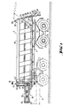
- the semitrailer 3 On the saddle 1 of a three-axle tractor 2 there is the semitrailer 3 with a self-supporting structure 4, which at its rear end is set up at 5 for receiving a double axle 6 or 7 with single tires 8 or 9.
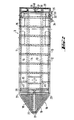
- a box structure which, according to the plan view according to FIG. 2, has parallel longitudinal walls 10 and 11 and a flat bottom 12 on two parallel longitudinal beams 13 and 14 and a plurality of cross beams 15.
- the box thus forms a self-supporting structure.
- the box At its front end, the box carries a frame, generally designated 16. This has a cross member 17, converging side parts 18 and 19 and parallel frame members 20 and 21, which are connected to the converging side parts 18 and 19 and to the box itself.
- a multiple cylinder piston arrangement 23 is articulated on the crossmember 17 via a horizontal joint 22.
- the end of the piston rod 24 of the arrangement 23 in turn sits above a horizontal joint 25 in a push plate 26 which forms the end face of the box, the rear end wall of which is formed by a pivotable flap 28.
- This flap 28 is fastened with its upper edge in two lateral joints 29 (FIG. 1) on the upper edge of the box at 30.
- a cylinder piston arrangement 32 can be pivoted with a cylinder piston arrangement 32 from its closed position shown in solid lines in FIG. 1 into the open position shown in broken lines.
- the cylinder 33 is articulated on a horizontal joint 34, while the piston rod is articulated on the flap 28 via a horizontal joint 35.
- the flap can be locked with a further hydraulic cylinder piston arrangement 36.
- the locking cylinder 37 (FIG. 1) is articulated at 38 to the flap 28, while its piston rods 39 are articulated at 40 to a locking bolt 41, which can snap into a corresponding recess 42 in an obliquely downward extension 43 of the base.
- the push plate 26 consists of a rectangular frame 45 consisting of hollow profiles, which is covered on both sides with a sheet 46 b or 47.
- An upper angle section 44 serves as a baffle, i.e. as a weir, which prevents the bulk material from overflowing over the upper edge (upper frame cross member of the push plate 26). It is connected to a further profile 45 'which is triangular in cross section and which forms a baffle bar which runs around the frame around the scuff plate 26, so that the push plate 26 can compress the load on its end face.
- the thrust shield 26 has a block 50 made of a low-friction plastic on both sides at the bottom.
- the Dlock slides in a longitudinal guide 51, which is formed by a box profile, the bottom 52 of which is connected to the side plate 53 of the relevant side wall 10 of the body.
- a baffle 56 extending from the inside of the upper side wall 54 of the box section 51 obliquely from the inside to the side wall 10 serves to repel the bulk material and is wiped off by a correspondingly shaped plate 57 of the push plate 25.
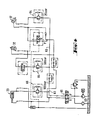
- the differential pressure circuit shown in FIG. 4 shows that the various cylinder piston arrangements are controlled in such a way that the multiple cylinder piston arrangement 23 cannot move the push plate 26 in front of the closed rear flap 25.
- a low pressure initially builds up in the line 63, which, according to the exemplary embodiment shown, must rise to 25 bar before the piston ring surface of the piston-cylinder arrangement 37 is acted upon by the switching and safety valve arrangement 64 and the release bolt is pulled out.
- the flap is pivoted up by the circuit 65 assigned to the piston-cylinder arrangement 32, before the control 66 assigned to the multiple-cylinder piston arrangement can be activated by increasing the pressure to 100 bar and sets the thrust plate 26 in motion.
- the vehicle is loaded through its upper opening 67 (FIG. 1) in a conventional manner.
- the rear panel flap 25 is closed and the push plate 26 is in the front end position shown in FIG. 1.
- the transport is carried out.
- the hydraulic circuit shown in FIG. 4 is actuated in accordance with the differential pressures described above, so that first the locking of the rear wall flap 28 is released, then the flap is pivoted up from its initial position shown in FIG. 1 into the end position shown in broken lines and finally the Thrust plate 26 can be set in motion from left to right in the illustration of FIG. 1 with the aid of the multi-cylinder piston arrangement 23.
- the load in box 3 is pushed out backwards over the inclined surface 41.
- the vehicle moves forward in order to apply a thin layer of 10 to 20 cm thick in accordance with the unloading and driving speed.
Landscapes
- Engineering & Computer Science (AREA)
- Mechanical Engineering (AREA)
- Transportation (AREA)
- Loading Or Unloading Of Vehicles (AREA)
- Auxiliary Methods And Devices For Loading And Unloading (AREA)
- Reciprocating Conveyors (AREA)
Claims (1)
Applications Claiming Priority (7)
| Application Number | Priority Date | Filing Date | Title |
|---|---|---|---|
| DE19782853229 DE2853229A1 (de) | 1978-12-09 | 1978-12-09 | Als lastkraftwagen oder lkw-anhaenger, insbesondere auflieger ausgebildetes fahrzeug |
| DE19782853282 DE2853282A1 (de) | 1978-12-09 | 1978-12-09 | Als lastkraftwagen oder lkw-anhaenger, insbesondere auflieger ausgebildetes fahrzeug |
| DE2853282 | 1978-12-09 | ||
| DE2853229 | 1978-12-09 | ||
| DE2943943 | 1979-10-31 | ||
| DE19792943943 DE2943943A1 (de) | 1979-10-31 | 1979-10-31 | Lkw oder lkw-anhaenger, insbesondere auflieger mit muldenaufbau fuer schuettguttransport und schubschild als entladevorrichtung |
| EP19790104468 EP0012227B1 (fr) | 1978-12-09 | 1979-11-13 | Semi-remorque pour transporter des matériaux en vrac |
Related Parent Applications (1)
| Application Number | Title | Priority Date | Filing Date |
|---|---|---|---|
| EP79104468.8 Division | 1979-11-13 |
Publications (2)
| Publication Number | Publication Date |
|---|---|
| EP0065249A1 EP0065249A1 (fr) | 1982-11-24 |
| EP0065249B1 true EP0065249B1 (fr) | 1986-02-05 |
Family
ID=27432361
Family Applications (1)
| Application Number | Title | Priority Date | Filing Date |
|---|---|---|---|
| EP82104027A Expired EP0065249B1 (fr) | 1978-12-09 | 1979-11-13 | Procédé pour stocker des matières en vrac, notamment des remblais repris au terril ou des terres provenant du lavage |
Country Status (2)
| Country | Link |
|---|---|
| EP (1) | EP0065249B1 (fr) |
| AT (2) | ATE3263T1 (fr) |
Families Citing this family (11)
| Publication number | Priority date | Publication date | Assignee | Title |
|---|---|---|---|---|
| DE3869981D1 (de) * | 1987-01-22 | 1992-05-21 | John Barber | Fahrzeuge fuer guttransport. |
| FR2722152A1 (fr) * | 1994-07-05 | 1996-01-12 | Coder Pomiers Industries | Benne pour transport de materiaux en vrac a dechargement par poussoir coulissant |
| US6062803A (en) * | 1995-02-03 | 2000-05-16 | Mcneilus Truck And Manufacturing, Inc. | Replaceable ejector slide tubes |
| US5971694A (en) * | 1997-01-31 | 1999-10-26 | Ncneilus Truck And Manufacturing, Inc. | Packer wear shoes |
| US6062804A (en) * | 1997-08-21 | 2000-05-16 | Caterpillar Inc. | Load carrying body and ejector arrangement |
| FR2823476B1 (fr) * | 2001-04-12 | 2003-09-05 | Fabrice Pomiers | Dispositif hydraulique et electro-pneumatique de controle de l'ejection d'un contenu au moyen d'une paroi mobile et methode de mise en oeuvre au sein d'une sequence d'ejection |
| US7326023B2 (en) | 2002-02-25 | 2008-02-05 | Hagenbuch Leroy G | Rear eject body for off-highway haulage units |
| US7901009B2 (en) | 2006-09-14 | 2011-03-08 | Hagenbuch Leroy G | Severe application off-highway truck body |
| US8702367B2 (en) | 2007-03-21 | 2014-04-22 | Edw. C. Levy Co. | Method, and process for preparing a recyclable material |
| US9803324B2 (en) | 2016-01-26 | 2017-10-31 | Deere & Company | Ejector control for spreading material according to a profile |
| US20170210266A1 (en) * | 2016-01-26 | 2017-07-27 | Deere & Company | Ejector control for spreading material |
Family Cites Families (3)
| Publication number | Priority date | Publication date | Assignee | Title |
|---|---|---|---|---|
| US1705901A (en) * | 1927-01-26 | 1929-03-19 | Joseph H Coombs | Material spreader |
| US3953170A (en) * | 1973-04-30 | 1976-04-27 | Golay & Co., Inc. | Dump truck with ejector blade |
| DE2842442B2 (de) * | 1978-09-29 | 1981-03-12 | Friedrich 4272 Kirchhellen Weyrich | Verfahren zum Aufhalden von körnigem Waschbergen des Steinkohlenbergbaus und Fahrzeug zu dessen Durchführung |
-
1979
- 1979-11-13 EP EP82104027A patent/EP0065249B1/fr not_active Expired
- 1979-11-13 AT AT79104468T patent/ATE3263T1/de not_active IP Right Cessation
- 1979-11-13 AT AT82104027T patent/ATE17841T1/de not_active IP Right Cessation
Also Published As
| Publication number | Publication date |
|---|---|
| EP0065249A1 (fr) | 1982-11-24 |
| ATE3263T1 (de) | 1983-05-15 |
| ATE17841T1 (de) | 1986-02-15 |
Similar Documents
| Publication | Publication Date | Title |
|---|---|---|
| DE3835748C1 (fr) | ||
| EP0405428A1 (fr) | Véhicule de ramassage d'ordures | |
| EP0065249B1 (fr) | Procédé pour stocker des matières en vrac, notamment des remblais repris au terril ou des terres provenant du lavage | |
| DE2040885A1 (de) | Materialzufuehreinrichtung,insbesondere Transportfahrzeug zur Zufuehrung von Asphalt zu einer Asphaltiermaschine | |
| EP0012227B1 (fr) | Semi-remorque pour transporter des matériaux en vrac | |
| DE2628325A1 (de) | Vorrichtung zum beschicken eines fertigers fuer bituminoese belaege | |
| DE3524463A1 (de) | Fahrbare lademaschine | |
| DE4213925C2 (de) | Wagenzug zum Speichern und für den Transport von Schüttgut | |
| DE2821461C2 (de) | Lastkraftwagen oder Lkw-Anhänger zum Transport von Schüttgut | |
| EP0060966B1 (fr) | Dispositif pour l'amassage et le transport des ordures | |
| DE2858139C2 (de) | Verfahren zum Aufhalden von Waschbergen | |
| DE3210338C2 (fr) | ||
| DE19838979C1 (de) | Streugerät | |
| DE8320290U1 (de) | Beladevorrichtung für kastenförmige Großbehälter | |
| DE19537085A1 (de) | Silobeschickungsvorrichtung | |
| DE2260396A1 (de) | Transport- und foerdervorrichtung sowie transport- und foerderverfahren | |
| DE7814780U1 (de) | Als Lastkraftwagen oder Lkw- Anhänger, insbesondere Auflieger ausgebildetes Fahrzeug für den Schüttguttransport | |
| AT247730B (de) | Fahrzeug mit kippbarer Ladebrücke und Transportmulde | |
| DE3725019C2 (fr) | ||
| DE2803053A1 (de) | Vorrichtung zum fortlaufenden auffuellen von graeben, aushebungen u.dgl. mit material | |
| DE3238641A1 (de) | Muellbehaelter | |
| DE2705687A1 (de) | Fahrzeug zum regenerieren von bituminoesen flaechen, insbesondere strassendecken, mit bearbeitungswerkzeugen und vorratsbehaelter fuer bituminoeses material | |
| DE1658563A1 (de) | Vorrichtung zum Einfuellen und Einebnen von Schuettgut in an verfestigte Fahrbahnen angrenzenden Laengsstreifen | |
| DE1634880C3 (de) | Schürfkübelfahrzeug | |
| DE19716427A1 (de) | Müllsammelvorrichtung für Abfälle und Transportmittel mit einer Müllsammelvorrichtung |
Legal Events
| Date | Code | Title | Description |
|---|---|---|---|
| PUAI | Public reference made under article 153(3) epc to a published international application that has entered the european phase |
Free format text: ORIGINAL CODE: 0009012 |
|
| 17P | Request for examination filed |
Effective date: 19820508 |
|
| AC | Divisional application: reference to earlier application |
Ref document number: 12227 Country of ref document: EP |
|
| AK | Designated contracting states |
Kind code of ref document: A1 Designated state(s): AT BE CH FR GB IT LU NL SE |
|
| GRAA | (expected) grant |
Free format text: ORIGINAL CODE: 0009210 |
|
| AC | Divisional application: reference to earlier application |
Ref document number: 12227 Country of ref document: EP |
|
| AK | Designated contracting states |
Designated state(s): AT BE CH FR GB IT LU NL SE |
|
| REF | Corresponds to: |
Ref document number: 17841 Country of ref document: AT Date of ref document: 19860215 Kind code of ref document: T |
|
| ITF | It: translation for a ep patent filed | ||
| ET | Fr: translation filed | ||
| PLBE | No opposition filed within time limit |
Free format text: ORIGINAL CODE: 0009261 |
|
| STAA | Information on the status of an ep patent application or granted ep patent |
Free format text: STATUS: NO OPPOSITION FILED WITHIN TIME LIMIT |
|
| 26N | No opposition filed | ||
| ITTA | It: last paid annual fee | ||
| PGFP | Annual fee paid to national office [announced via postgrant information from national office to epo] |
Ref country code: LU Payment date: 19920924 Year of fee payment: 14 |
|
| PGFP | Annual fee paid to national office [announced via postgrant information from national office to epo] |
Ref country code: GB Payment date: 19921028 Year of fee payment: 14 Ref country code: AT Payment date: 19921028 Year of fee payment: 14 |
|
| PG25 | Lapsed in a contracting state [announced via postgrant information from national office to epo] |
Ref country code: LU Free format text: LAPSE BECAUSE OF NON-PAYMENT OF DUE FEES Effective date: 19921113 |
|
| PGFP | Annual fee paid to national office [announced via postgrant information from national office to epo] |
Ref country code: FR Payment date: 19921116 Year of fee payment: 14 |
|
| PGFP | Annual fee paid to national office [announced via postgrant information from national office to epo] |
Ref country code: SE Payment date: 19921125 Year of fee payment: 14 |
|
| PGFP | Annual fee paid to national office [announced via postgrant information from national office to epo] |
Ref country code: NL Payment date: 19921130 Year of fee payment: 14 |
|
| PGFP | Annual fee paid to national office [announced via postgrant information from national office to epo] |
Ref country code: BE Payment date: 19921207 Year of fee payment: 14 |
|
| PGFP | Annual fee paid to national office [announced via postgrant information from national office to epo] |
Ref country code: CH Payment date: 19921218 Year of fee payment: 14 |
|
| EPTA | Lu: last paid annual fee | ||
| PG25 | Lapsed in a contracting state [announced via postgrant information from national office to epo] |
Ref country code: GB Effective date: 19931113 Ref country code: AT Effective date: 19931113 |
|
| PG25 | Lapsed in a contracting state [announced via postgrant information from national office to epo] |
Ref country code: SE Effective date: 19931114 |
|
| PG25 | Lapsed in a contracting state [announced via postgrant information from national office to epo] |
Ref country code: CH Effective date: 19931130 Ref country code: BE Effective date: 19931130 |
|
| BERE | Be: lapsed |
Owner name: ROTHALIT BAU- UND WEGEBAUSTOFFE G.M.B.H. Effective date: 19931130 |
|
| PG25 | Lapsed in a contracting state [announced via postgrant information from national office to epo] |
Ref country code: NL Effective date: 19940601 |
|
| GBPC | Gb: european patent ceased through non-payment of renewal fee |
Effective date: 19931113 |
|
| NLV4 | Nl: lapsed or anulled due to non-payment of the annual fee | ||
| PG25 | Lapsed in a contracting state [announced via postgrant information from national office to epo] |
Ref country code: FR Effective date: 19940729 |
|
| REG | Reference to a national code |
Ref country code: CH Ref legal event code: PL |
|
| REG | Reference to a national code |
Ref country code: FR Ref legal event code: ST |
|
| EUG | Se: european patent has lapsed |
Ref document number: 82104027.6 Effective date: 19940610 |